Week Twelve: Output Devices
Goal
add an output device to a microcontroller board you've designed and program it to do something
Week Twelve: Output Devices Objectives
- Design something to output - in EagleCAD
- Make it - On the Modela
- Program it -
- Test it
Design Something to Output
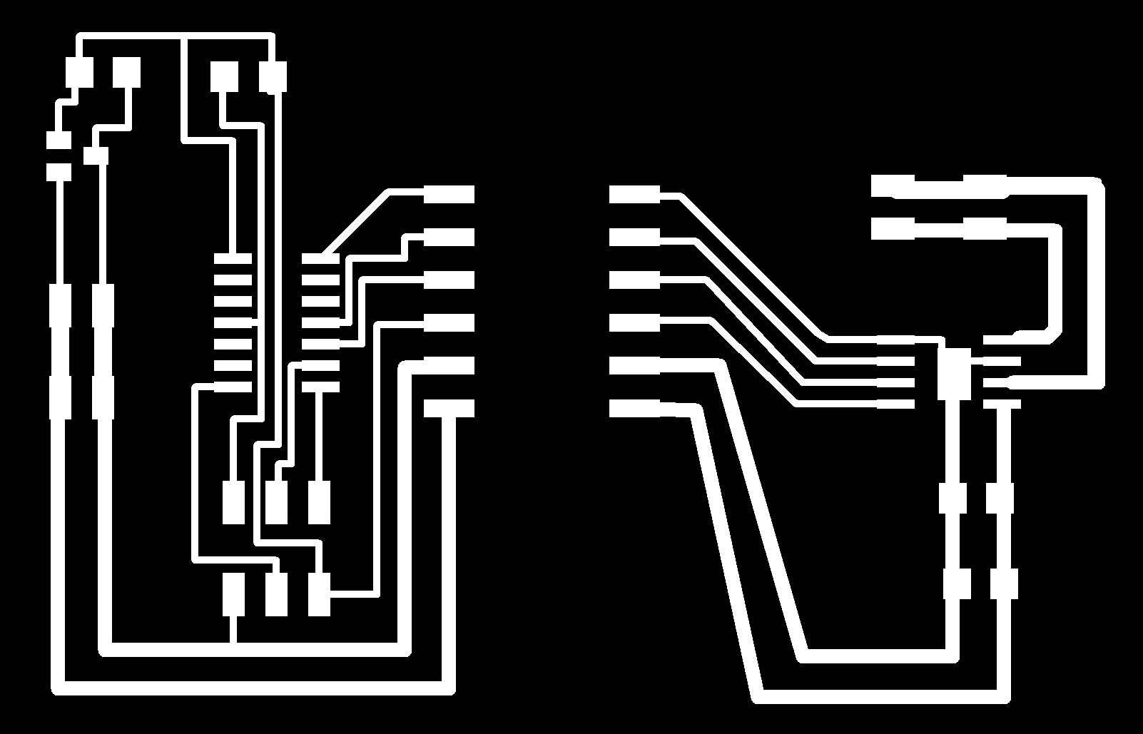
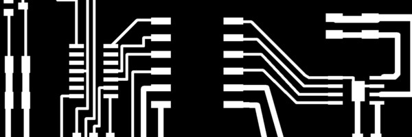
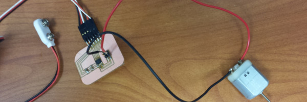
I decided to make a breakout board for the dc motor. I used Eagle CAD for the design, mainly because I could not get the electronic functions to work on kokopelli. I wanted to design and make another breakout board with a DC motor. Basically I took Neil's design and separted the components needed for the motor and put them on a separte board. Now the board can be used with other boards.
While designing the board I could not find the H - Bridge component. With the help of Adam Harris, I noticed the bridge had the same footprint used the ATTINY 45. I used the ATTINY 45 layout However, when I tried to connect to the pins in the schematic the program would not let me. So I went into the layout and connected the wires. Furthermore, the two boards are on the same file saving cut time.
Make it
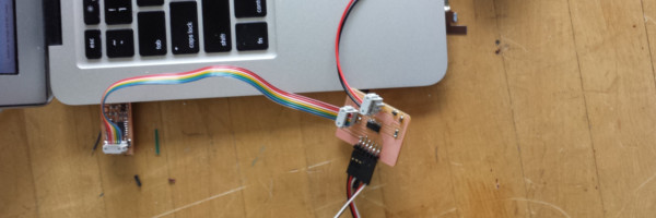
Once I exported the schematics to a PNG file I uploaded the traces and the border to the fab modules. I milled out the boards with no problem. I am a lot more comfortable milling boards. I did the usual, got the components ready. However, getting the boards off the table of the mill was pressing. I used waaaaay to much tape. It took a rather long time to seperate the pcb from the table and ended up breaking the rest of the PCB.
I soldered up the ATTINY44 board with no problem. I was soldering the motor breakout board and I noticed the feet of the H-Bridge did not touch the pads on the board. Instead of stressing the chip I decided to use a heat gun. This was the first time I used it to take a component off. I was a bit skeptical, however, it worked like a charm. Then soldered the rest.
Program it
I first programmed the breakout board with Neil's code. I noticed the motor only ran when the FabISP was pluged into the computer. I asked the local expert Denny. Denny suggested it may be with the RST pin. I checked the voltage on the RST pin with the 9 volt plug in and with out there was a discrepence. However, it worked when it was plugged into the computer.
Then I tweaked it to run at full thottle.
Test it
Neil Gershenfeld's program running on the breakout board video.
Tutorials
- http://academy.cba.mit.edu/content/tutorials/akf/output_device_examples.html
- http://academy.cba.mit.edu/2012/students/mavros.cynthia/links.html
- http://octopart.com/
Errors
- http://fab.cba.mit.edu/classes/863.12/people/laia.mogassoldevila/projects/p6.html
Pin layouts
- http://www.instructables.com/id/How-to-drive-a-character-LCD-displays-using-DIP-sw/?ALLSTEPS