Week Four: Electronic Production
Goal
The fourth week goal was to make a version of the FabISP in-system programmer. Click HERE to learn more abot ISP
Week Four: Electronic Production Objectives
- Chose which ISP
- Connect Fab Modules to the Roland Modela
- Make the board on the Modela
- Solder components on the FabISP
- Program the ISP
Chose which ISP
I chose the FabISP Valentin's because it was a USB and it eliminated the wire therefore, in theory it is less expensive. Furthermore, I thought it was cool and more difficult because I had to mill the board twic, once for the circuit and the other for outline of the USB.
Connect Fab Modules to the Roland
So we were all set to connect the the Mac Book Air to the Roland Modela and could not connect. Luckily Francisco told us about the serial converter cable and the the appropiare serial-parallel connector we needed to make outlined below.
http://infosyncratic.nl/weblog/2013/08/22/talking-to-a-roland-modela-from-linux/
After we built the apdator I still could not get the Mac Book Air, something wrong with the USB ports on the Mac, so I gave up on the Mac and switched to one of the Linux machines in the lab. However, in the future I would like to run the Modela with the Mac.
Note: The below instructions were a team effort by Adam Harris and myself.
- Open a terminal window in linux (CTRL+ ALT + T)
- Add write permission for USB0: (This is a new one for me, Adam Harris helped me with this.)
- $ sudo adduser <username of linux device> dialout
- $ sudo chmod a+rw /dev/ttyU*
- Note: The fab modules expect the Modela to be at /dev/ttyUSB0
- $ sudo fab_update to see if you need to update the Fab Modules
- If need be, $ sudo fab_update install to intall the lateset Fab Modulese
- $ fab to run the Fab Modules
- Select input as PNG, output as Roland Models .rml and click the “make_png_rml” button to open the new window.
- Once in the new window, you must load the particular PNG file of your circuit or board outline. In the left column, click “load PNG” and select your file.
- Set the Z depth to -0.15 mm, set the speed to 3mm/s and set up your X and Y offsets. Be aware that your PCB image might already have an offset built in (the traces don’t usually start exactly on the edge of the image).
---------------------------------------------------------------------------------------------------------------------------

Make the board on the Modela
First, we needed the correct PCB, which could not find because we did not order any. I call Global XXX to order some because I could find FR4 on their webste. George at the place told me they do not sell that type of board. So I went to the local Radio Shack and the PCB board they sell, which I beleive is the FR4 material.
I placed the PCB to be cut on top of some sacrificial material - acryllic cut out on the laser cutter. The board you wish to cut should be on top. The second board is a sacrificial board so the when you cut all the way through the top one, it won't damage the bit or the machine’s table. Affix the sacrificial board to the mill’s metal table with flat 2-sided tape.
Note #1: The 0,0 coordinate of this machine is at the bottom left corner of the grid design on the metal plate.
Note #2: You cannot cut the PCB board in view mode.
- Now affix the PCB you wish to cut on top of the sacrificial material with flat 2-sided tape.
- If you are using scrap PCB material, move these offsets to a blank spot on the PCB. Click the “move to Xmin and Ymin” button to check this out. If the spindle doesn’t stop on its own, click the button again.
- For traces we will only use either the 1/64th inch bit or the 0.01” (10 mil) bit for this. Fab modules will automatically calculate the offsets for the thickness of the bit you choose. I used the 1/64” bit for my traces.
- Enter view mode on the modela by pushing the “view” button on the machine. The gantry should move to the back right and the table should come forward. Turn off the Modela before changing the bit!
- You can change the bit here. Put the bit in a couple of millimeters deeper than you normally would. It should stick out of the shank about 1.25 inches. Tighten the setscrew to snug.
- Take the modela out of view mode by pushing the “View” button on the machine. This will bring the drill to 0,0 on the X and Y (the drill will now be at the bottom left corner of the table) and the Z axis will be up in the air.
- Go back to the computer and click the “go to Xmin, ymin” button to move to the X and Y offset values you entered. The mill should move to this point. Don’t be alarmed if the spindle turns on. If the spindle does not automatically turn itself off again after the X and Y axes stop moving, click the “Go to Xmin, Ymin” button again.
- Press and hold the Z down buttons to move the Z axis to within a couple of millimeters of the top PCB. The spindle will turn on when the Z axis moves. Once you release the button, the spindle should stop. If it doesn’t, press the Z up button once.
- Now loosen the setscrew on the spindle and drop the bit until it touches the top of the PCB. Tighten the setscrew until it is snug.
- Now doublecheck your values for speed, Xmin, Ymin and Z depth. Once you have all the settings set as you like them, we will doublecheck everything is set up right with a simple checklist
- Click “Make Path” button again
- Click “move to Xmin, Ymin” button again
- Click “Make .rml” button to create the RML file. If needed, you can send this directly out the serial port to the machine with a terminal command such as $ cat ‘/home/cpcc/Desktop/fab_src/ab_mod_<name of original PNG file>.rm’ > /dev/ttyUSB0
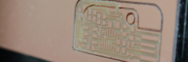
- We ran two different programs: once for the chip circuits and the other for the outline.
- Once complete I took the chip off with a box cutter. The chip was a little difficult to get out becuase the endmill did not cut all the way through the board, however, I use the knife to cut around the outside and taking the entire PCB off the Modela.
---------------------------------------------------------------------------------------------------------------------------

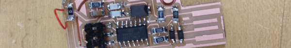
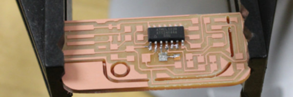
Solder components on the FabISP
Since, I have soldered before, there was little in terms of understaning, however, I had never SMS. This I was looking forward to. I heard it was extremely difficult. However, Once I got started it was not as difficult as I thought it would be. I had the right equipment, and got some good adivce from people in the lab. I soldered the chip on first then worked from the USB end to the other, this strategy worked like a charm. I tested each component after soldering, and noticed the 0 ohm resister was not a short, so I took a wire and was able to solder around the resistor.
Note: The #4 pin trace was connected to the crystal, so I took a box cutter and cut out the connection. The connection could be caused by the endmill or sloppy soldering.
--------------------------------------------------------------------------------------------------------------------

Program the FabISP
Programming the FabISP was not as hard as I initially thought, again due good advice from people in the lab. Below is what I did.
- First install the avr-libc and gcc-avr:
- $ sudo apt-get install avr-libc gcc-avr
- Download the firmware(http://fabacademy.org/archive/classes/embedded_programming/firmware.zip )
- Unzip the file and cd into:
- $ cd /firmware/fabISP_mac.0.8.2_firmware”
- Plug the AVRmk2 into the programmer as so that the cable is coming off the back side the board (opposite the USB plug)
- Plug the new programmer you made into the USB port (you need the USB port for power). (You may need to line the back with vinyl to make the PCB thick enough. The LED on the MK2 programmer will turn from red to green when the power is applied correctly.
- Using the AVRmkII(in avrdude it is called avrisp2) I followed the instructions below. I first made sure and checked the makefile and the programmer was selected as “avrisp2”
- $ make clean
- $ make hex
- $ sudo make fuse
- $ sudo make program
- I cut the excess portion of the PCB. This was extremely nerve racking, because I wa so close to the end and I did not want to mess it up.
- Make a 6-pin to 6-pin cable so that pin 1 on one side connects to pin 1 on the other side. to do this, make sure the alignment bumps face the same direction on the cable.
- I opened the terminal and cd into directory where files are $sudo avrdude -c usbtiny -p m328p -U flash:w:2secondBlink.hex (At first I did not use sudo, this does not work. You cannot write to a USB port unless you have privelages)
- Test by loading modified (to blink at 0.33 seconds) fastBlink.hex and slowersecondBlink.hex onto an arduino via the the ISP connector on the arduino.
It worked!!!
The overall experience was enlightening, although I know how to do most of what we did, I never did them all for one project.