Week Ten: Input Devices
Goal
measure something: add a sensor to a microcontroller board that you've designed and read it,
Week Ten: Input Devices Objectives
- Design a modular board with pins.
- Design shields/daughter boards
- Joystick
- Capacitive Sensor
- Write code
Design a Modular board with pins
The thought of designing shields or daughter boards intriques me. It seems the most elegant way to approach different sensors. The sensor is built seperate from the microcontroller. Therefore, if the sensor is damaged or not working properly it is easier to troubleshoot.
The sensors I would like to build are the Joystick, Touchpad and Hall Effect. Building the Joystick module is the first priority due to final project. The Touchpad and the Hall Effect because their freaking cool. I did not get to the Hall Effect Sensor, although it would be a great project for a later day.
For both input devices the workflow from the beginning to end is shown below:
- Design in EagleCAD
- Modify in Gimp
- Prepare in Fab Modules
- Cut on Roland Modela
- Solder components
- Write software
Joystick
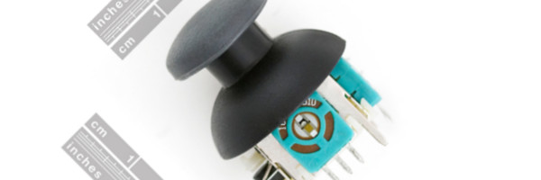
The Joystick I decided to read was a thumb joystick from Sparkfun. The joystick is used in game controllers, which use potentiometers, or pot for short, orthogonal to each other. Each pot ranges from 0 to 10 k ohms. The Joystick also has a button when pressed.
Design in EagleCad
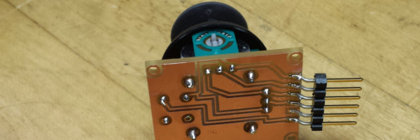
I used Eagle CAD in the embedded section before so I thought it would not be that hard. However, I understood the generalities of it I found the details lacking. This time I took better notes. For the daughter board I started with Sparkfun's Joystick Shield Eagle Cad file HERE and got to HERE.
After a conversation with Adam, who asked a great question, "How are you going to solder the joystick to the board?" I have reallynot thought of it, however, I needed to flip the board. But at what part of the workflow? I decided to flip the traces in Gimp.
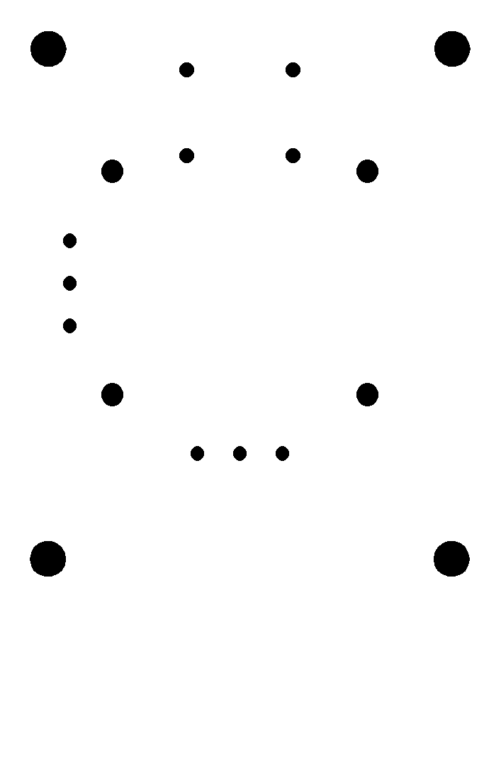
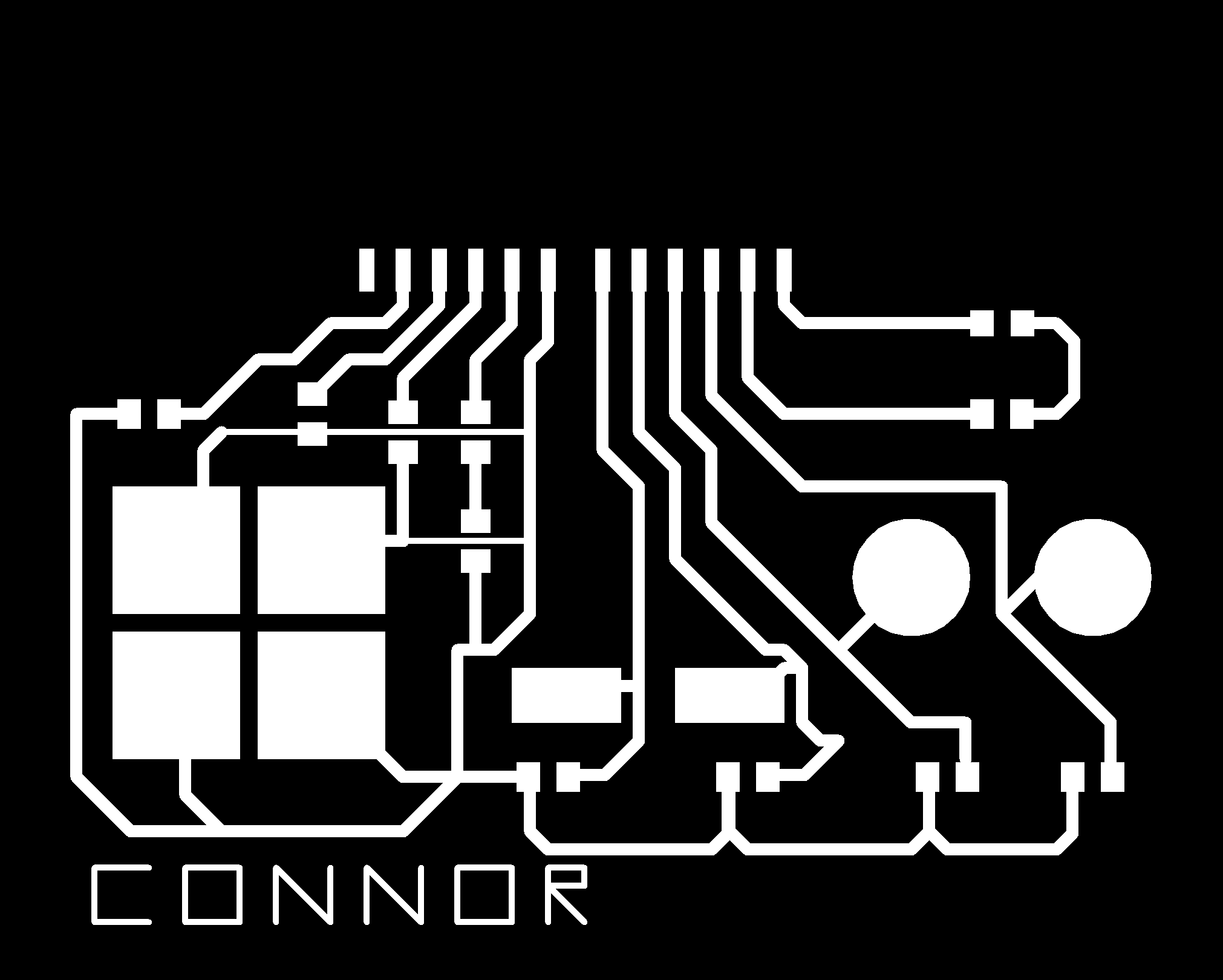
Once the traces and the boundary files were complete. They were eported to a PNG file with 600dpi and Monochrome.
Export png file.
- File -> Export -> Image
- Select Monochrome
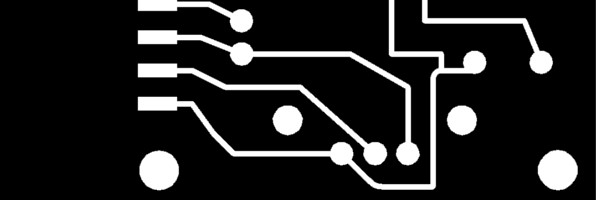
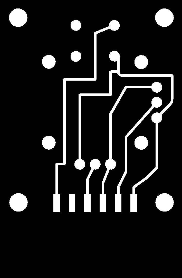
The trace file was opened in Gimp and flipped horizontally. A drill pattern was created, which was easier than I thought. Furthermore, the border file was opened and filled in.
Open in Gimp to flip and modify image
- Pilf part (HaHa!)
- Tools
- Transformation Tools
- Flip Horizontally (This is confusion, in CAD systems it is 90 degree difference)
- Fill outer circles with white
- Bucket fill icon
Workflow to create board:
- Mill holes in board
- mill traces
- cut out board
PNG files can be downloaded here:
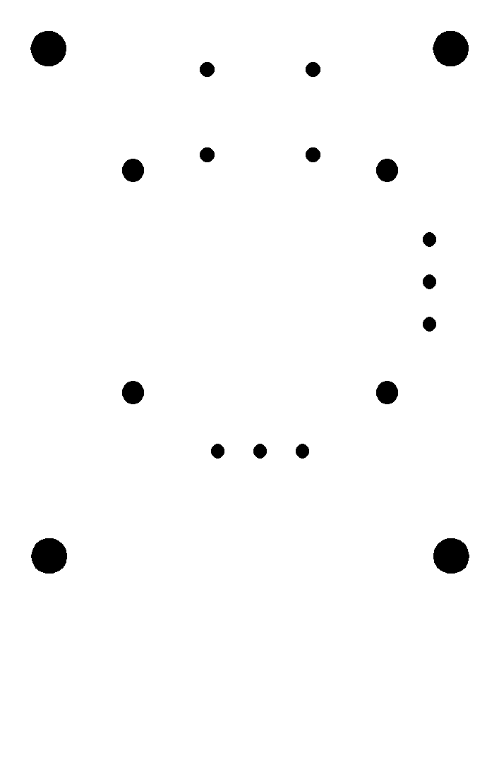
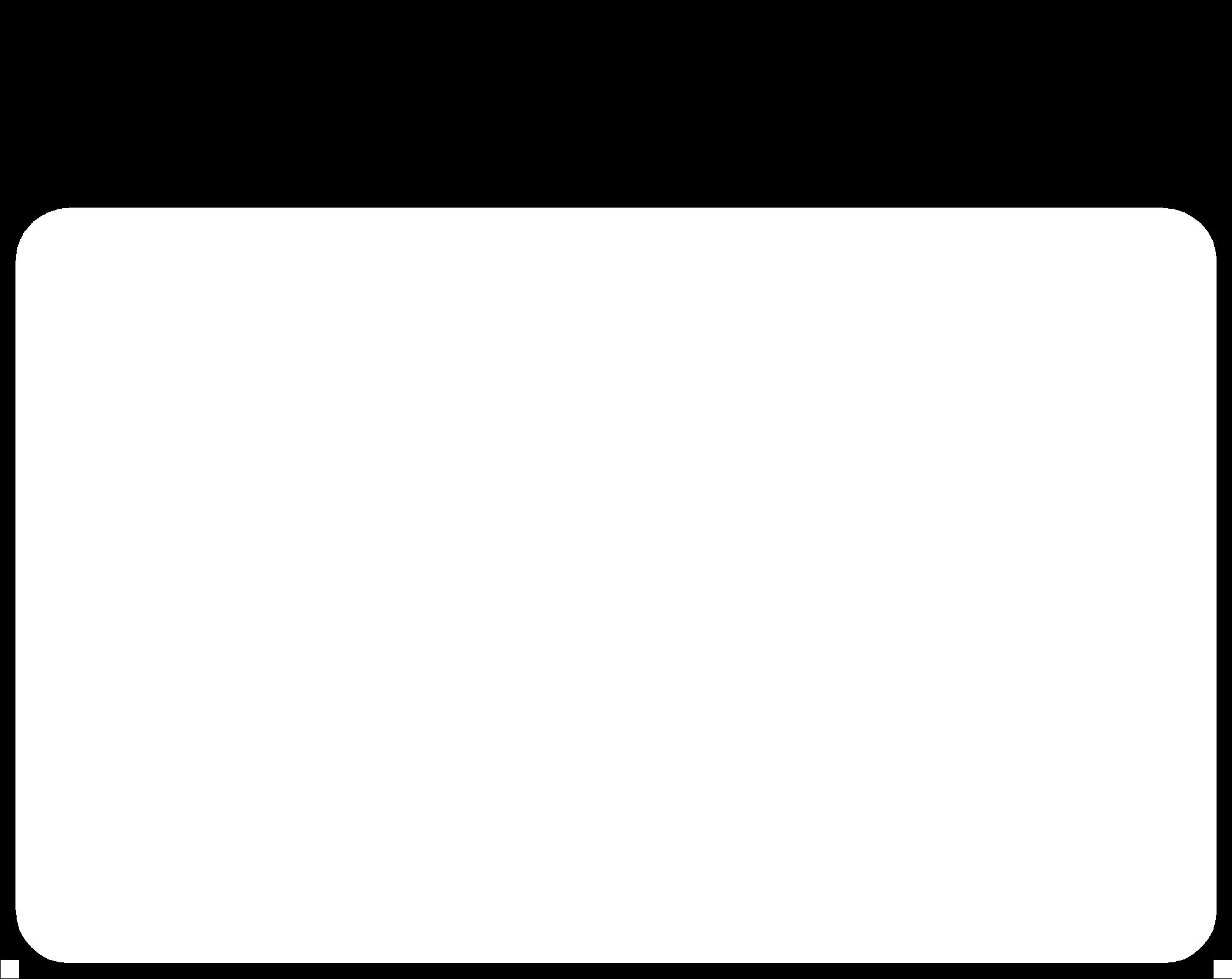
Border File - The border file follows the inside border.
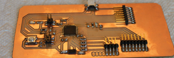
Update May 30th,2014I made my own embedded circuit comparable to the Leonardo called (The Little Bro Fab Leo) for my project which has inputs seen below. See Project page for information.
I used an Arduino Leonardo to test the device, because I can use the ATmega 32 U chip as an option for the game controller final project. We ordered the chips, however, we have not received them yet. When they come in I will build a comparable Leonardo board. This was to test both the joystick and the cap input devices.
The code emulates the key board functions to play Super Mario Bros on the computer. I could figure out how to jump using the "option" button on a MAC, so I modified Mario Brothers so "z" would jump. The code work, however, the button to jump did not work according to plan. When I used the Keyboard.write() command I could only get Mario to do a small jump. I needed to figure out how to get him to jump big as well.
You can download the code HERE.
You can download Super Mario Bros HERE.
Capacitive Sensor
The capacitive sensor is an elegant way to sense the world. There are no moving parts like a button or joystick. Once, I became aware of these it became apparent to me I could use a capacitve sensor for the game controller, simplifing my design completely. I just needed to find some libaries or write my own. I found Arduino libaries HERE. I used these for the game controller software.
Design in EagleCad
As stated above I used Eagle CAD as the design program. I am getting more and more familiar with the program the more I use it. Designing the cap sensors felt comfortable. I was familiar not just with the button, I am getting more familiar with the concepts. Electronics is a fascinating subject.
Discussing the project with Adam, he suggested to look at the Cap Sensors from Hack A Day - Click HERE. This project is awesome, they created a game controller out cap sensors to work with Nintendo System. This changed my design for my final project drastically. So I created a draft of the game controller's inputs. The inputs are all cap sensors, this simplifies the inputs. Plus, it makes it much more cooller looking design.
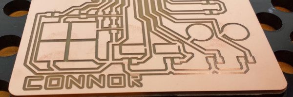
At this point, I had no trouble creating the sensors with the Roland Modela. I did want to test three different resistors for the sensors to see which one was more sensitive. I used 1, 5 and 10 M ohm resistors. For the rest I used 5 Mohm.
Once I created the board I needed to write the code. I heard this was very complicated. However, I found libraries in Arduino located HERE to use. Taking a look at the code and conversations with Adam helped a lot to understand what was going on . Although internalizing the concepts will take more time.
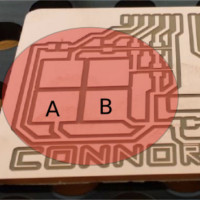
For some reason the 5 Mohm was the more sensitive. This was puzzling me, however, hen testing I realized a flaw in the design. In the below picture buttons A and B are on the same strand. This causes some unintended consequences. When testing the buttons on the game I could not move Mario to the left or the right because the lines were getting confused. Another flaw is if I touch the controller it changes the capacitance, I wonder about shielding. WARNING if you download the file please modify to fix. This will be fixed in the fixed in the final design. Getting close to figuring out how to construct the controller.
You may download the files below.
- Eagle CAD schematic
- Eagle CAD board
- PNG trace file
- PNG Outline
- Controller code - You must download and install the Arduino Cap Sensor library first.
Experiences and questions I had along the way:
Below are some questions and answers I had along the way. Writing these questions/answers will help me solidify my learning.
How do you measure distance in Eagle CAD?
There is a dimensions tab on the tool bar towards the bottom. This came in handy when I needed it.
How do I autoroute? It keeps giving the error "The layer '16 ()' is not available in the layer setup.
You can either disable the layer here or enable it in the Design Rules." This turned out to be a corrupt file.
How do I undo a autoroute?
type "ripup;" in the text bar
How do I move the entire Layout?
Click the move button, click the group button, CNTRL + pad, Move: Group
How do I transfer one item to another layer?
- Click on the i (information)
- Click on item
- In the properities window and next to the Layer tab you modify te layer.
I like the pin swap, it quite possibility come in handy.
How to I dynamically zoom in and out on a MAC?
Take two fingers on the track pad and seperate or close them.
Fab Modules
Notes about the Fab Modules
When setting up to mill the endmill only mills around the white space not the entire black space.
Milling the traces I modified the overlap to .8 because .5 gave me a unsastifactory finish.
RoHS - Standard for Lead free.
In the fab modules I am confusd where the zero starts from the png file. To deal with this I decided to put a dot where the 0 point is in eagle CAD.
Make sure the endmill can go to the depth.
ON Soldering
I decided to test three different resistors for the cap sensors.
- R1 = 1Mohm - label: 1004
- R2 = 4.99 Mohm - label: 4994
- R3 = 10 Mohm - label: 5001
According to the test
Test
Tested different resistor values to see which on is more sensitve.
Found an error in the design the bottom left pads are the same. This will cause unintened consenquences.
Resources:
EagleCad
- Autorouter Tutorial https://www.youtube.com/watch?v=4xjjahxMapc
- ripup; - http://43oh.com/2011/11/tip-eagle-pcb-undo-autorouting-in-one-step/
Kokopelli
- Converting CAD files to .ko files - https://github.com/mkeeter/kokopelli/wiki/Porting-old-files
Some Other
- Cap Sensors from Hack A Day - Click HERE
- Cap Sensors - https://www.youtube.com/watch?v=BHQPqQ_5ulc
- Arduino - http://playground.arduino.cc/Main/CapacitiveSensor?from=Main.CapSense#.U0BENK1dXmZ
- https://learn.adafruit.com/introducing-bluefruit-ez-key-diy-bluetooth-hid-keyboard/sending-keys-via-serial
- http://www.ti.com/lit/an/slaa363a/slaa363a.pdf