#8 Computer-controlled machining
My approach to this assignment was starting with some experimentation. I found that it is a great way for me to do things and learn to get better results. Without a definitive project for the assignment, I started doing some testing with different patterns for hinges and joints. I knew that in the process, some ideas would come to me for the SOMETHING BIG assignment. I love patterns, and the idea of bending and flexing rigid materials just by cutting different patterns fascinates me. I followed the same process for Week #3 and it went really well.
After some lectures on how to use the ShopBot software (VCarve), and some hands-on practicing with the machine, I started my design.
I used Adobe Illustrator, as I am very familiar with that program, and also because flat design is very suitable for this kind of machining. At the end I used a flat design and with the software I made all the necessary arrangements to send the info to the machine for the cutting process.
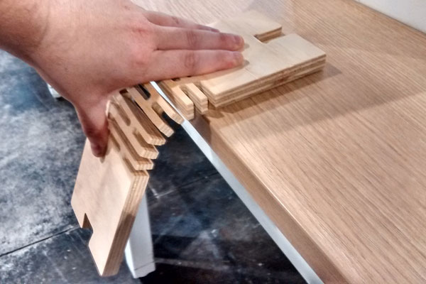
I made 4 different patterns for the hinges. All of them had 12mm of separations between the lines, so cutting them with 1/4 inc mill, the holes and the lines would be 6mm wide. The differences between the designs were the lengths of the lines, and how they reach the edges of the cut.
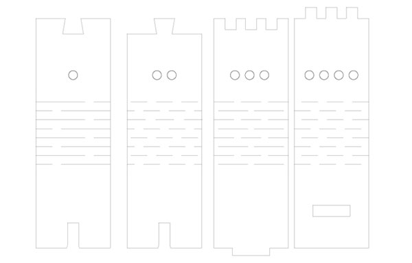
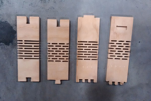
After the experimentation phase, I found that in order to reach the flexible point, the lines have to go all the way to the rim in both edges.
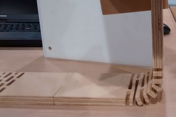
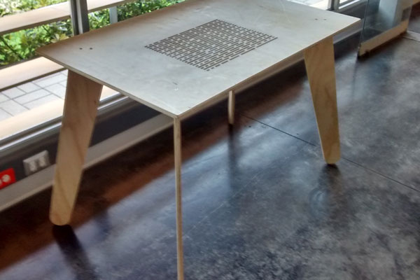
Now it was time to design something big. I decided that I wanted something I could use. So I saw that my living room needed was a desk for my laptop. I started designing but something was missing. It was too simple, 1 board with 4 legs. At that moment, a nice piece of art came to my mind, one that I had seen many years ago at the Pompidou Museum in Paris. It was about the Fibonacci sequence:
0,1,1,2,3,5,8,13,21,34, and so on, where each subsequent number is the sum of the previous two.
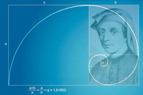
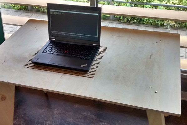
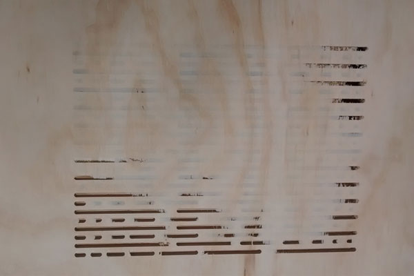
So I designed the dimensions and proportions of the table based on those numbers. I made a pattern to ventilate the laptop that represents the sequence, in a spiral using the Golden Ratio. For the legs I got inspired on Nordic design styles but also used the Fibonacci sequence for the relationship between the bottom and the top of the legs.
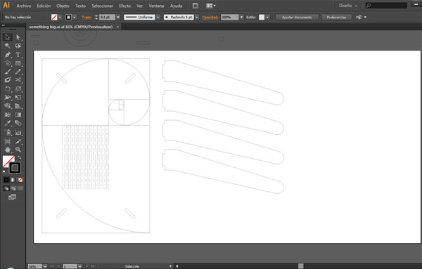
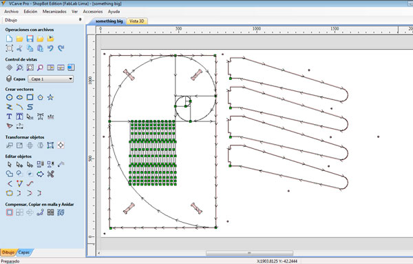
Once I had my design on Adobe Illustrator, I exported it to a DXF extension and opened it on VCarve to make all the the routes and parameters for the cutting on the Shopbot.
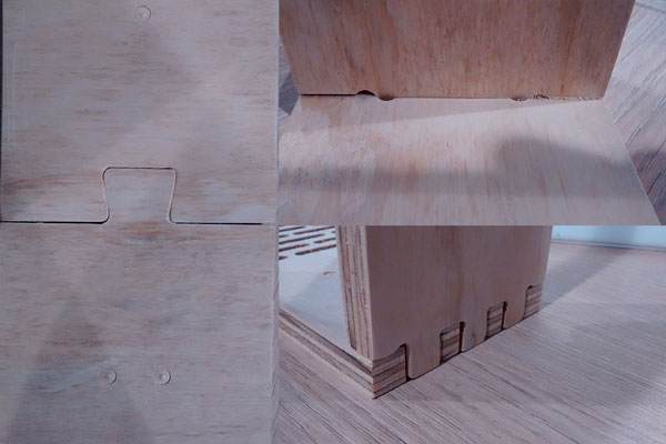
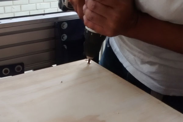
First I used the drills to attach the Plywood (15mm) to the sacrifice board. Then I wanted to engrave the Fibonacci spiral, so I set a 1mm depth. After that came the slots for the legs joints, followed by the cutting of the pattern, and finally the outer cutting of the pieces in which I used taps to keep all the pieces in place.
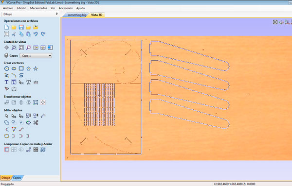
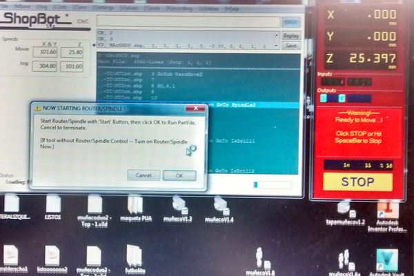
Once all of this was done, I saved it with an SBP(mm) extension and opened it at the Shopbot station, ready for making the cuts.
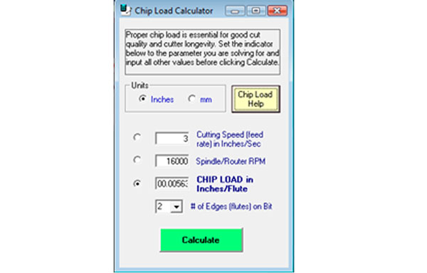
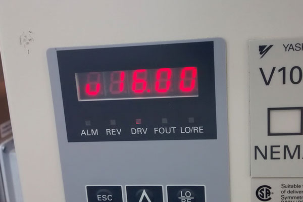
First of all I checked the chip load. I set the speed of the spindle at 16000 RPM and the cutting speed at 3 inches/sec. Those parameters worked.
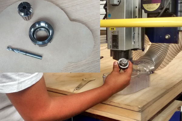
I used the 1/4 Up-Cut milling cutter.
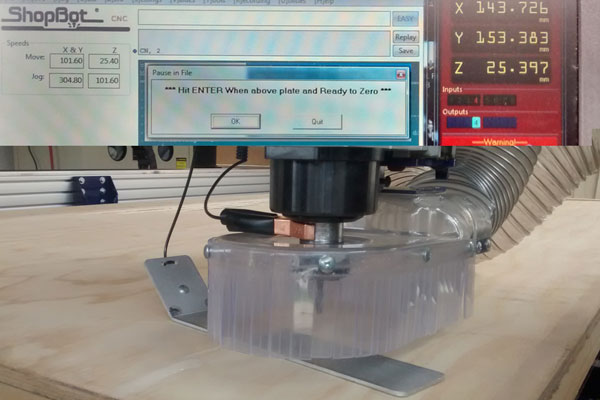
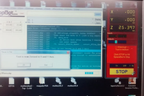
Then It was time to calibrate the axis. First Z and then X,Y. Finally, I had to set up the spindle speed.
Now I was ready for cutting.
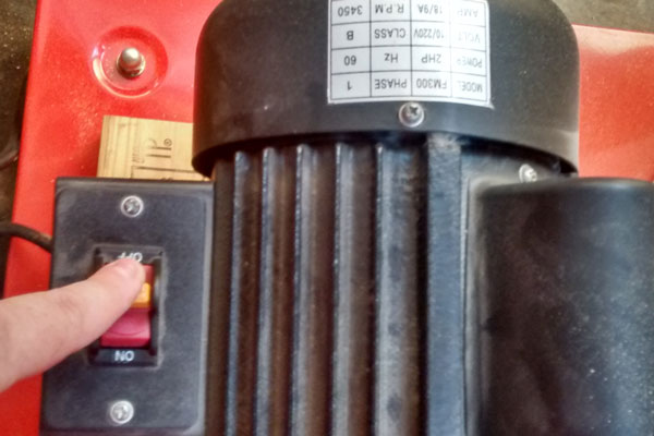
It was important not to forget to turn on the spindle and the chip vacuum.
First, the drills.
After that I sent the complete work to the Shopbot. It took close to one hour to finish everything.
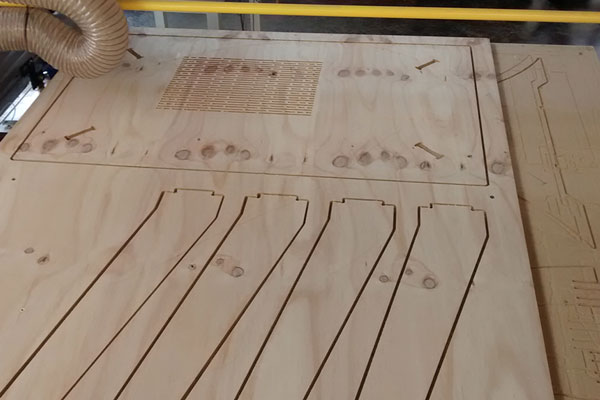
The moment of truth finally came: it was time to take everything out of the machine and see the results.
I had some issues.
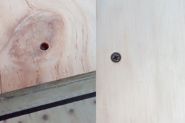
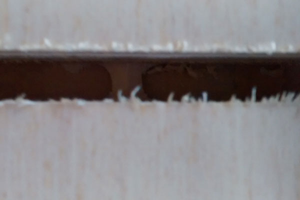
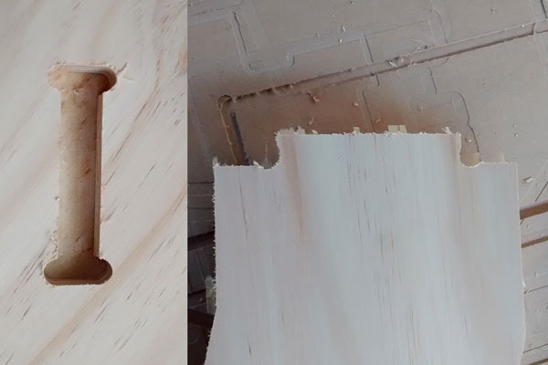
The first thing I noticed was that the patterns weren't cut all the way through the plywood. That was odd because although the width of the material is 15mm, I set up the cutting depth at 16mm. I assume the material was bent, and the screws that I distributed over the sheet weren't enough to get it flat. This problem had a very straightforward solution: sanding everything well.
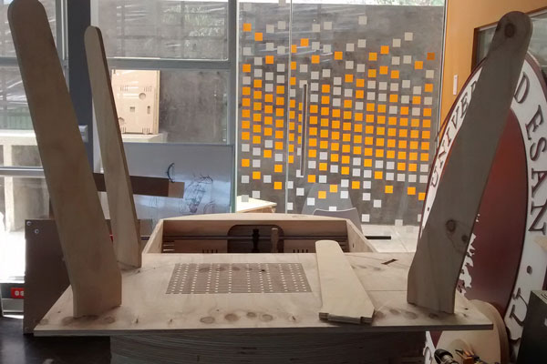
After that, the more crucial step was to insert the legs into the slots. Only two of them were ok, and the other two were a little narrow. I assume again that the error was due to the bent plywood. In this case the solution was more complicated. I had to decide to open up the slots a bit, or narrow down the legs. I used a Dremel for this operation, but wasn't quite precise. I did a bit of this and a bit of that but it still did not work out. The table was too unstable, and some of the things that were placed on top even fell out. I was kind of frustrated, so at the end I decided to put some screws to attach the legs to the tabletop.