
#11 Output devices
This week I decided to make my "Fabduino", for which I used Anna Kaziunas tutorial. The only thing I changed was the name of the plate, and baptized as "MARDUINO 2015".
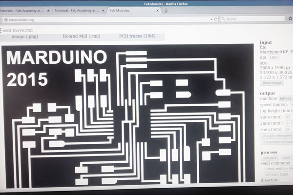
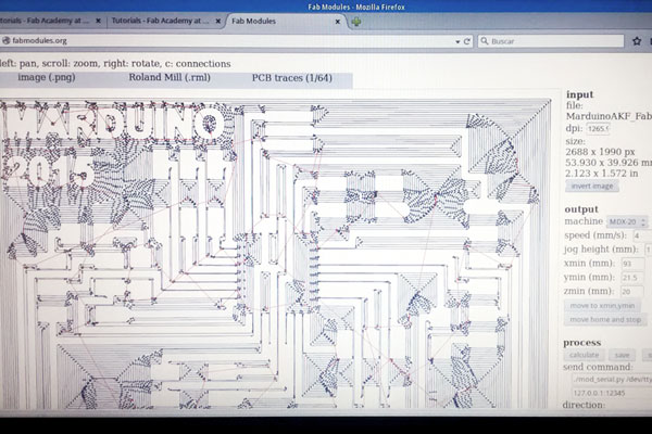
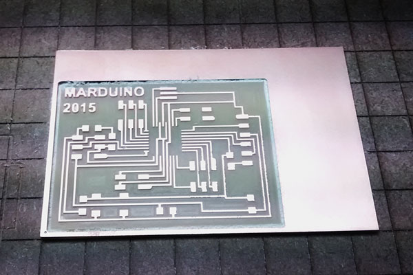
The milling process was flawless using the fabmodules.
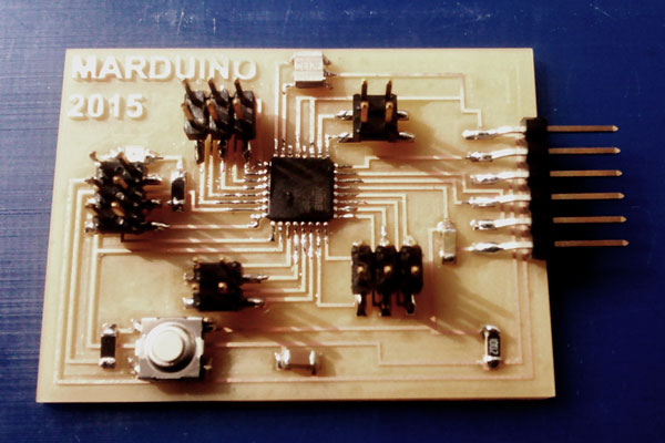
Solder the components was a bit tricky, especially ATMEGA328P. Finally, with a little patience and some skill I could finish the whole soldering, with which I was very pleased.
Then came the time of programming.
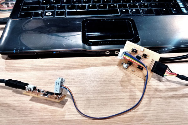
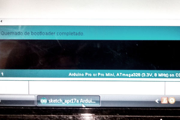
First I use my FabISP to flash the bootloader from arduino and apparently was done correctly. I did it using Windows Vista. But I failed to add the necessary boards provided by Fab webpage.
For that I had to run the program from Ubuntu, this time including the boards. This time the process went successfully.
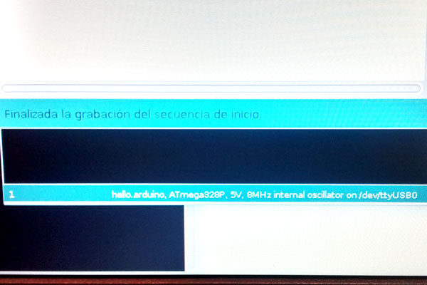
Finally got my Marduino ready to use.
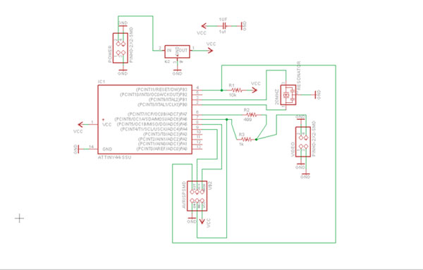
For the assignment of this week I decided to try Video device because it will serve me for my final project.
First I designed the card in EAGLE. I made the schematic and then routed the traces.
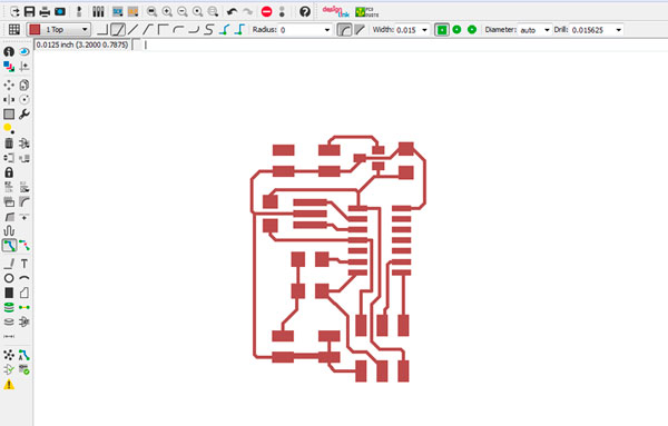
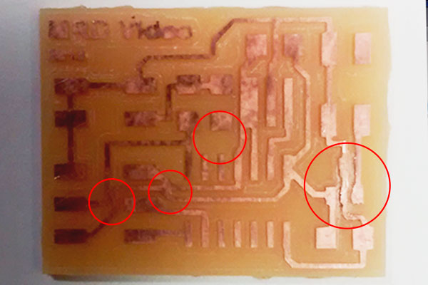
When sent to mill the design, I realized that went wrong.
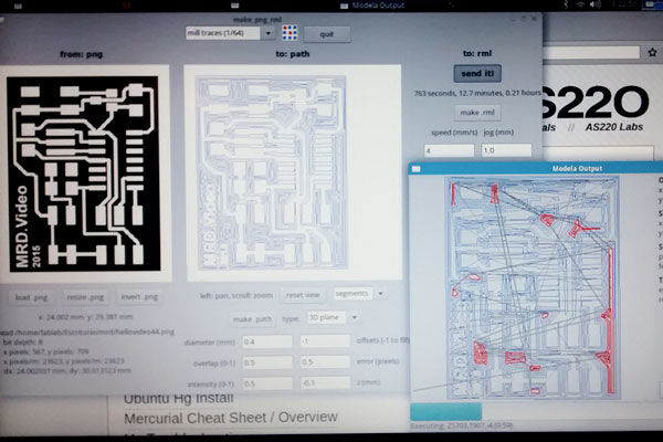
There were several traces that had been attached to each other. I even realized I had missed some routes.
So I had to correct the error in EAGLE to later re-milling.
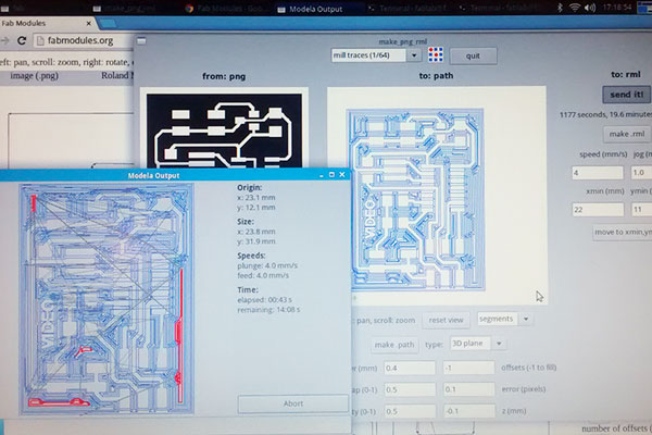
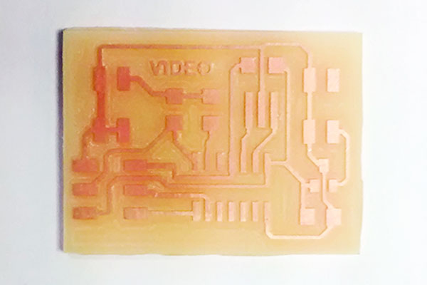
This time the card is impeccable.
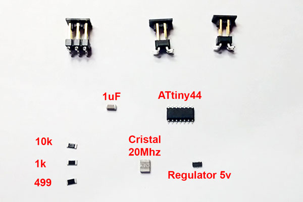
And then the soldering.
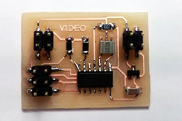
Using the FabISP and arduino, embed the code that was on the page.
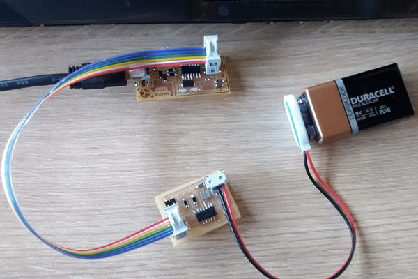
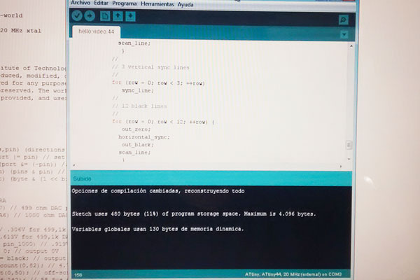
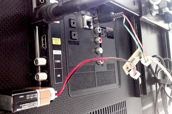
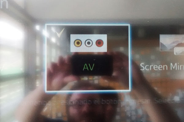
With my board ready and powered by a 9 volt battery I went to try it. I experimented with the video input on a TV but did not work, although it did acknowledge a signal.
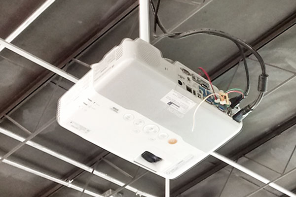
Then I experimented with a projector but neither got positive results.
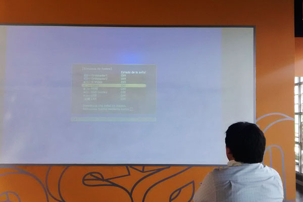
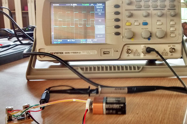
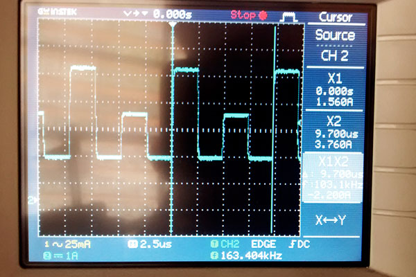
Finally I tried the oscilloscope to see if there was any signal effectively, and in this case I got positive results.According to the instrument, my board emits a signal, but nevertheless could not be conveyed visually on a device.
A test is pending with an analog TV, and also to review the code in depth, to see if there is some setting changes I can do.
UPDATED
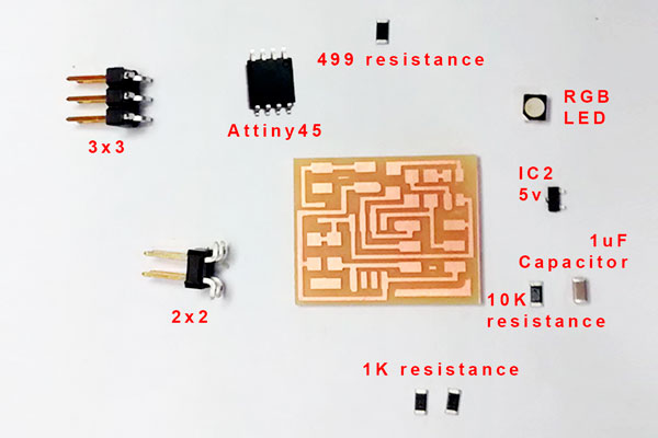
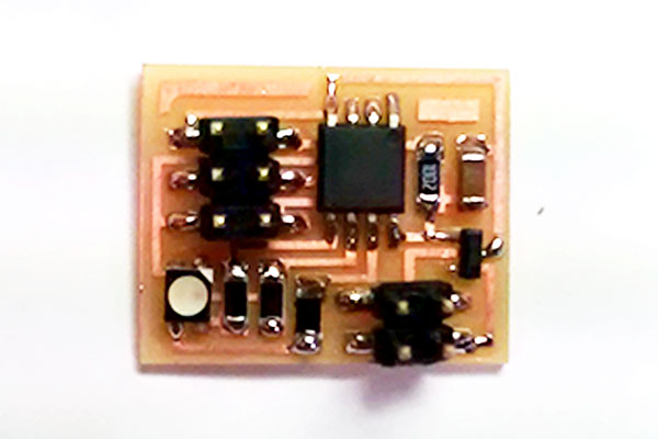
I decided to try another card and chose the RGB LED.
I milled the PCB Board with the Modela and then soldered all components.
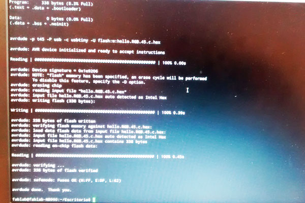
Then I flashed the board in Ubuntu with the code that on the page of the Academy
sudo make -f program-usbtiny hello.RGB.45.make
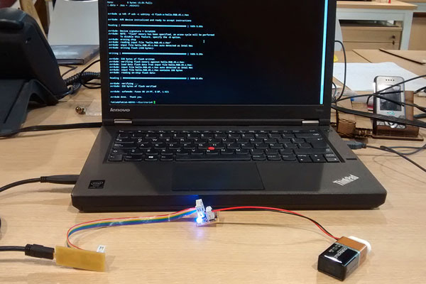
Done, the code causes the LED will change color.
All the files for the RGB LED are in the Academy page.
Back To Top