Week 3- Computer Controlled Cutting
Helpfully, during my time at FabLab London I’ve had lots of opportunities to use their lazer cutter, so having experience cutting and etching, this will be my chosen tool. An example of thing’s I’ve done with the laser cutter already can be found here and here.
The goal of this week’s homework was to design and make a press fit construction kit.
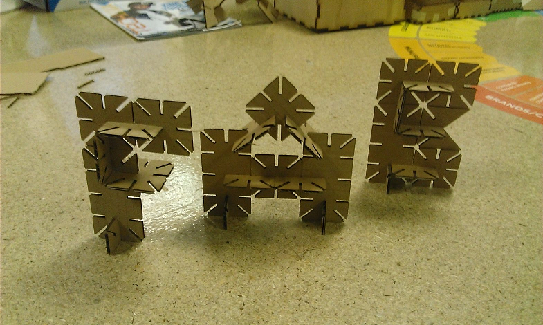
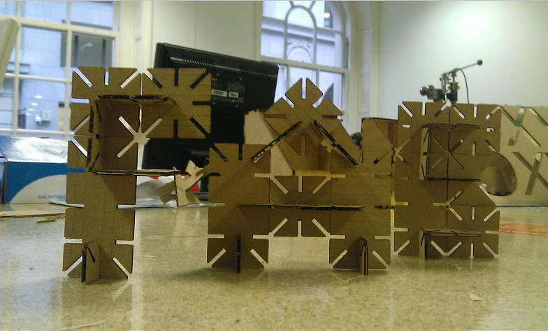
My idea was a set of joints and cut outs that can be arranged to spell ‘FAB’ in 3D.
The first job was to work out what cut settings I would use. To do this I cut out a small square using Trotec’s recommended settings for cardboard, which luckily worked perfectly, so I decided to stick with them.
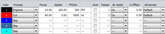
The cut settings I chose.
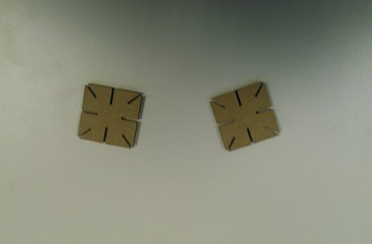
First joint prototype
Next was to make a couple of test joints. Having measured the width of my cardboard to be 4mm, I set the width of my joints to be 4.Unfortunately, I hadn’t realized the default units in Ink scape are pixels not mm, so when it came to cutting the joints they appeared far too small. I decided to have joints in the corners as well as on each side, as I felt it would give me more freedom when using them.
Another fabacademy student in the lab had cut out a shape with multiple sized joints and their specifications, so it was easy to test to see what size joints would work the best. I used it to decide to make my joints 2.7mm. I then went on to make two more prototypes which you can see below; the first was to test the joint width, and the second I decided to make my joints smaller to save resources.
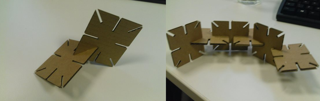
Joints prototype 2 and 3
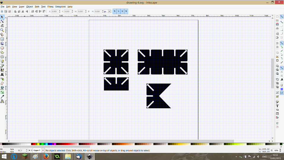
I made some final changes to prototype 3 (namely making it more square) before making some variations of the design. Here’s a screen capture of my inkscape file.
Again, I cut out a few of these joints just to make sure everything was okay, before cutting out a lot more and arranging them to spell the word ‘FAB’!