Lesson 12 - Output devices
We have started with an introduction to
the Relay component.
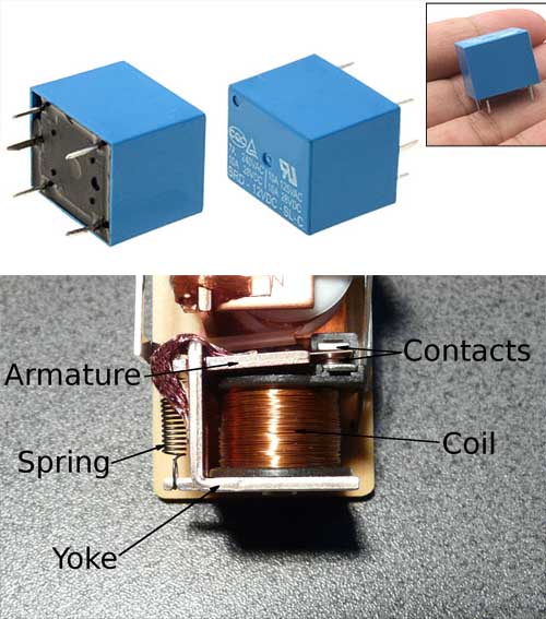
The component can basically switch the power and control the circuit for output devices
it works on magnetic pulses created thanks to a coiled coil
and mechanically close or open the current to flow from one end or another.
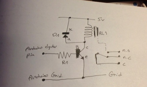
We have designed a scheme of a circuit with a relay component on it.
The circuit had a diode, resistor, microcontroller and a transistor.
We understood the terms of N.C and N.O (normally closed and normally open)

We have tested the circuit before plugging an output to it.
we have used the "blink" code from Arduino as our test drive.
Thanks to the fact that the Relay is semi mechanical, there is a "clicking" sound each time the switch is changing.
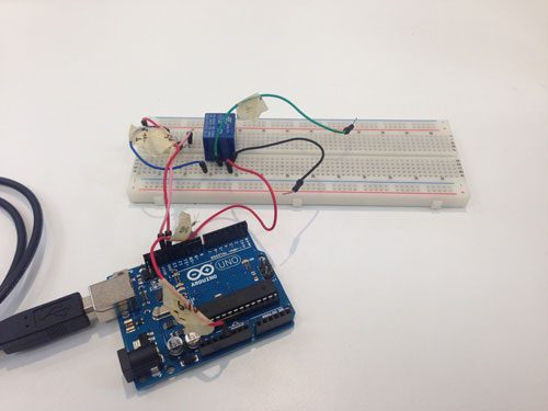
I have wired all the components on a bread board and was assisting the Arduino
in order to explore and understand the functionality of the devices with the code.
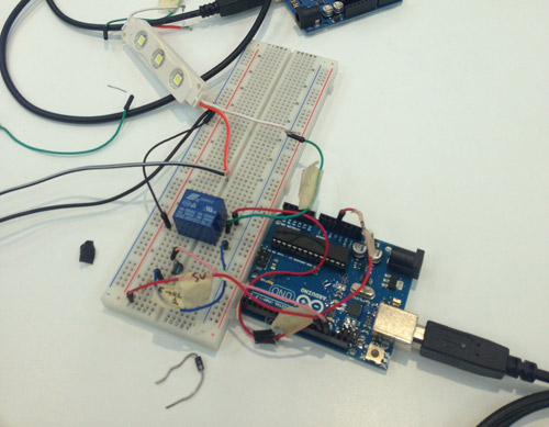
I have connected 3 LED's to the circuit and I had the ability to determine when and for how long they will be lit
thanks to the blink code.
Later on we have disconnected from the USB port as a power supply and we used the local electricity network in order to lit the LED's
Considering the fact that the assignment for this week was also to create the board
The following image will be the scheme that I will use in the future as the main layout


Copyright 2014 | Designed by Oded Shorer