Lesson 10 - Input Devices
Self learning
I am a big fan of self learning, I really enjoy to share the knowledge and learn from others.
For some of us the world of programming is clear and obvious, and make a lot of sense
But for me..it is a whole new language, in a different world...so, like a good tourist,
I took the guide and started to explore.
but then I realized that this world is huge, and there's so many places to visit,
and there are so many dialects, and customs and....
I got lost.
When I just started the fab academy, one of the first things that appealed to me was the programming, the ability to "talk" to the device through sensors and computer,
but nobody mentioned that it should be made in 1 week and by myself. Our mentors are great, and they are doing their best in order to help us go through the weekly tasks
but, sometimes we are missing so much...because we are running after the task,
instead of learning the methods to fulfill it.
Getting started
Even tough, we could have used our boards with the Attiny 45 as the micro controller,
and have a natural continuation with our devices and boards
As far as I saw the task was to understand INPUT,
Therefore, I have choosing the fastest way of connectivity, in order to start the real thing,
while knowing that I can do the solder later on.
I have used Arduino UNO, Bread board, and the FTDI connector. the sensor Is Photo transistor that was solder on a board.

I have connected the wires from the board to the bread board to the Arduino.
Ground to Ground, VCC to VCC and A0 (analog leg) to the sensor.
I have opened the Arduino and set the board to the necessary configuration
- AAtin 45, and the COM port which the FTDI is connected to.

CODE
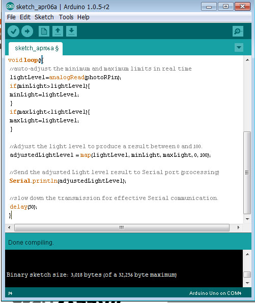
I was editing a preset code of photocell - sensing light for Arduino
code:
int photoRPin = 0;
int minLight;
int maxLight;
int lightLevel;
int adjustedLightLevel;
void setup() {
Serial.begin(9600);
Setup the starting light level limits
lightLevel=analogRead(photoRPin);
minLight=lightLevel-20;
maxLight=lightLevel;
}
void loop(){
auto-adjust the minimum and maximum limits in real time
lightLevel=analogRead(photoRPin);
if(minLight>lightLevel){
minLight=lightLevel;
}
if(maxLight
Adjust the light level to produce a result between 0 and 100
adjustedLightLevel = map(lightLevel, minLight, maxLight, 0, 100);
Send the adjusted Light level result to Serial port (processing)
Serial.println(adjustedLightLevel);
slow down the transmission for effective Serial communication.
delay(50);
}
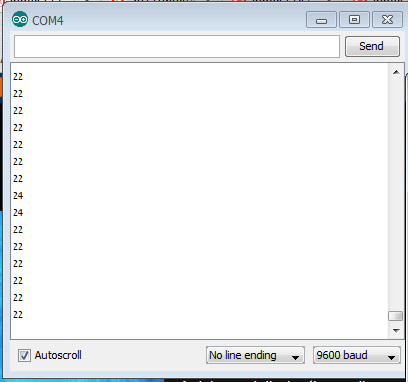
I was changing the intervals and saw the relative reaction from the sensor by blocking and unblocking the light


Processing
The processing introduction was nice.
somehow, everything related to the visual aspect of things
seems to be much easier and comprehended to me
than just letters and numbers...
but i guess this is an issue for another session with another professional...
To present the process of the input I have used the following code:
import processing.serial.*;
Serial myPort;
String sensorReading="";
PFont font;
void setup() {
size(400,200);
myPort = new Serial(this, "COM13", 9600);
myPort.bufferUntil('\n');
font = createFont(PFont.list()[2],32);
textFont(font);
}
void draw() {
//The serialEvent controls the display
}
void serialEvent (Serial myPort){
sensorReading = myPort.readStringUntil('\n');
if(sensorReading != null){
sensorReading=trim(sensorReading);
}
writeText("Sensor Reading: " + sensorReading);
}
void writeText(String textToWrite){
background(255);
fill(0);
text(textToWrite, width/20, height/2);
and that was the result.

later on, we had a mini experiment with the firefly for grasshopper based on Rhino.
it was a successful and exciting to see the shapes changing according to the input.
I am still on the process of learning, will submit images soon.
