Building a 3d model on rhino5 of an axis head to run some tests
A longtime ago I’ve learned rhino at school and that’s the reason I used it for these task.
First I started by drawing a circle , than using offset curve
 I drew more concentric circles that I copied to a certain distance, by making a line
  and using mirror
  in the mid point of that line. From there i made more horizontal and vertical lines using some of the above tools, and used trim
  to take out the some parts off the lines leaving behind just some out lines do extrude my model.
Press Fit
I started my press fit task based on a triangle as base material I used some old 3mm acrylic from a store front.
2nd - some basic ideas I already have in mind…( at this point everything is changeable):
Motors - I intend to use dc motors for many reasons, the 1st one being they are more common, then it's easier to buy a used powerful one. And, as I recovered many encoders from hp printers, I can get the proper positioning feedback I need; and the 2nd reason is that I'm going to learn how to read and control input and output devices, nothing better than combine them both on my final project. With hi-torque, both stopped and in motion, good gear reduction, hi-durability and being available as cheap used parts, I found car window and windscreen wiper motors to be apparently ideal for my project…
input devices
For input device I chose an optic rotary encoder from an old hp printer.
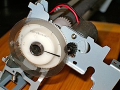
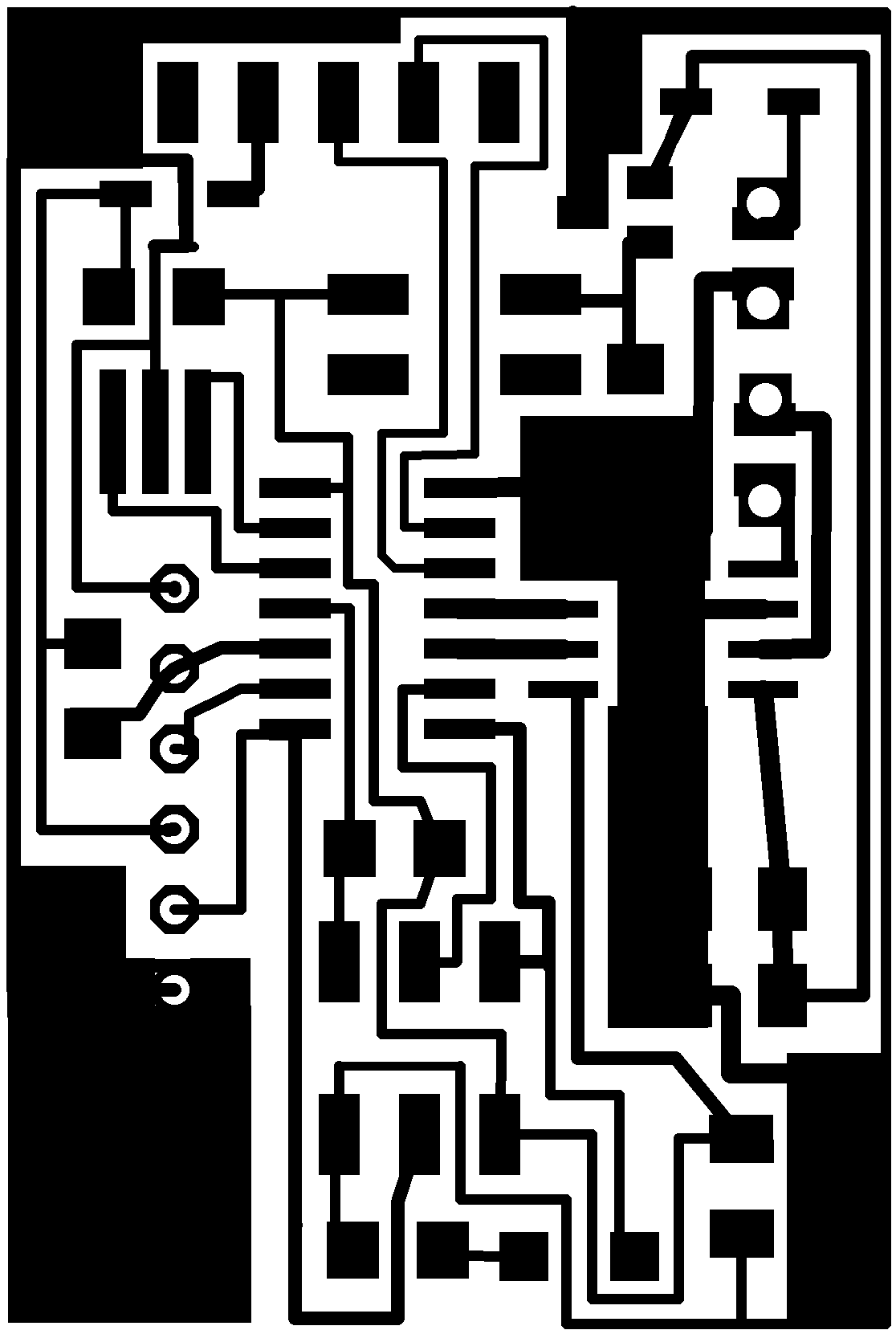
I found the data-sheet and it depicted a standard circuit that only included one 1uf capacitor and I realized it was already included on little hp circuit board that supported the encoder. So as I have been reading the Attiny44 data-sheet and I understood that in it I had enough capable pins to read the encoder , drive a motor, read a limit switch and communicate by serial port. As designing a board just for the encoder wouldn't be a challenge in EAGLE (which besides the paying version, has a Light Edition that proved more than adequate), I decided to make a mix of Neal's “hello boards” with a led for debugging, a h-bridge for driving a DC motor, Tx and Rx connection, external button connection and, of course, a connection for the encoder.
At the same time I started trying to get some readings from the encoder with an arduino board. As it has the serial communications pre-embedded, I got both digital an analog reading and I ended up with a simple program that reads 2 digital pins and prints 1 when they are high and 0 when they are low. Then I tried to export it to attiny44.
First I learned that I could charge Neal's C programs through Arduino IDE, which came in handy as I had some problems with the command line from win 8.1 . Then some alterations to the code had to be made for the serial to work. I took Neal's “ hello.ftdi.44.echo.c" programm and combined it with the previous one I had made for Arduino, ending up with this sketch:
#include < avr/io.h >
#include < util/delay.h>
#include < avr/pgmspace.h>
#define output(directions,pin) (directions |= pin) // set port direction for output
#define input(directions,pin) (directions &= (~pin)) // set port direction for input
#define set(port,pin) (port |= pin) // set port pin
#define clear(port,pin) (port &= (~pin)) // clear port pin
#define pin_test(pins,pin) (pins & pin) // test for port pin
#define bit_test(byte,bit) (byte & (1 << bit)) // test for bit set
#define bit_delay_time 8.5 // bit delay for 115200 with overhead
#define bit_delay() _delay_us(bit_delay_time) // RS232 bit delay
#define half_bit_delay() _delay_us(bit_delay_time/2) // RS232 half bit delay
#define char_delay() _delay_ms(10) // char delay
#define serial_port PORTA
#define serial_direction DDRA
#define serial_pins PINA
#define serial_pin_in (1 << PA1)
#define serial_pin_out (1 << PA0)
#define ENCODER_PORT PORTA
#define ENCODER_DIR DDRA
//#define ENCODER1_PIN (1 << PA7)
//#define ENCODER2_PIN (1 << PA6)
const int ENCODER1_PIN = 6; // the number of the pushbutton pin
const int ENCODER2_PIN = 7;
#define max_buffer 25
void get_char(volatile unsigned char *pins, unsigned char pin, char *rxbyte) {
//
// read character into rxbyte on pins pin
// assumes line driver (inverts bits)
//
*rxbyte = 0;
while (pin_test(*pins,pin))
//
// wait for start bit
//
;
//
// delay to middle of first data bit
//
half_bit_delay();
bit_delay();
//
// unrolled loop to read data bits
//
if pin_test(*pins,pin)
*rxbyte |= (1 << 0);
else
*rxbyte |= (0 << 0);
bit_delay();
if pin_test(*pins,pin)
*rxbyte |= (1 << 1);
else
*rxbyte |= (0 << 1);
bit_delay();
if pin_test(*pins,pin)
*rxbyte |= (1 << 2);
else
*rxbyte |= (0 << 2);
bit_delay();
if pin_test(*pins,pin)
*rxbyte |= (1 << 3);
else
*rxbyte |= (0 << 3);
bit_delay();
if pin_test(*pins,pin)
*rxbyte |= (1 << 4);
else
*rxbyte |= (0 << 4);
bit_delay();
if pin_test(*pins,pin)
*rxbyte |= (1 << 5);
else
*rxbyte |= (0 << 5);
bit_delay();
if pin_test(*pins,pin)
*rxbyte |= (1 << 6);
else
*rxbyte |= (0 << 6);
bit_delay();
if pin_test(*pins,pin)
*rxbyte |= (1 << 7);
else
*rxbyte |= (0 << 7);
//
// wait for stop bit
//
bit_delay();
half_bit_delay();
}
void put_char(volatile unsigned char *port, unsigned char pin, char txchar) {
//
// send character in txchar on port pin
// assumes line driver (inverts bits)
//
// start bit
//
clear(*port,pin);
bit_delay();
//
// unrolled loop to write data bits
//
if bit_test(txchar,0)
set(*port,pin);
else
clear(*port,pin);
bit_delay();
if bit_test(txchar,1)
set(*port,pin);
else
clear(*port,pin);
bit_delay();
if bit_test(txchar,2)
set(*port,pin);
else
clear(*port,pin);
bit_delay();
if bit_test(txchar,3)
set(*port,pin);
else
clear(*port,pin);
bit_delay();
if bit_test(txchar,4)
set(*port,pin);
else
clear(*port,pin);
bit_delay();
if bit_test(txchar,5)
set(*port,pin);
else
clear(*port,pin);
bit_delay();
if bit_test(txchar,6)
set(*port,pin);
else
clear(*port,pin);
bit_delay();
if bit_test(txchar,7)
set(*port,pin);
else
clear(*port,pin);
bit_delay();
//
// stop bit
//
set(*port,pin);
bit_delay();
//
// char delay
//
bit_delay();
}
void put_string(volatile unsigned char *port, unsigned char pin, char *str) {
//
// print a null-terminated string
//
static int index;
index = 0;
do {
put_char(port, pin, str[index]);
++index;
} while (str[index] != 0);
}
int main(void) {
//
// main
//
static char chr;
static char buffer[max_buffer] = {0};
static int index;
//
// set clock divider to /1
//
CLKPR = (1 << CLKPCE);
CLKPR = (0 << CLKPS3) | (0 << CLKPS2) | (0 << CLKPS1) | (0 << CLKPS0);
//
// initialize output pins
//
set(serial_port, serial_pin_out);
output(serial_direction, serial_pin_out);
//input(ENCODER_DIR, ENCODER1_PIN);
//input(ENCODER_DIR, ENCODER2_PIN);
//
// main loop
//
index = 0;
while (1) {
if (digitalRead(ENCODER1_PIN) == HIGH){
// right 1:
put_char(&serial_port, serial_pin_out, '1');
}
else {
// right 0:
put_char(&serial_port, serial_pin_out, '0');
if (digitalRead(ENCODER2_PIN) == HIGH){
// right 1:
put_char(&serial_port, serial_pin_out, '1');
}
else {
// right 0:
put_char(&serial_port, serial_pin_out, '0');
}}
see https://drive.google.com/folderview?id=0B-zSpF8Sy3QLM0pIZmw4c1lRb1k&usp=sharing for files
Guilherme Moreira | 18-01-2014 | 04:46 AM | Lisboa | Portugal | para Fab Academy 2014 (pt)