Building a 3d model on rhino5 of an axis head to run some tests
A longtime ago I’ve learned rhino at school and that’s the reason I used it for these task.
First I started by drawing a circle , than using offset curve
 I drew more concentric circles that I copied to a certain distance, by making a line
  and using mirror
  in the mid point of that line. From there i made more horizontal and vertical lines using some of the above tools, and used trim
  to take out the some parts off the lines leaving behind just some out lines do extrude my model.
Press Fit
I started my press fit task based on a triangle as base material I used some old 3mm acrylic from a store front.
2nd - some basic ideas I already have in mind…( at this point everything is changeable):
Motors - I intend to use dc motors for many reasons, the 1st one being they are more common, then it's easier to buy a used powerful one. And, as I recovered many encoders from hp printers, I can get the proper positioning feedback I need; and the 2nd reason is that I'm going to learn how to read and control input and output devices, nothing better than combine them both on my final project. With hi-torque, both stopped and in motion, good gear reduction, hi-durability and being available as cheap used parts, I found car window and windscreen wiper motors to be apparently ideal for my project…
Final project
Where do I start? Well, lets begin with the aluminium casting: with the available conditions I could not do the casting because of bad weather, we had to do the smelting outdoors: the structure had to be totally revised from a more definitive option with the aluminium structure to a more mock-up like solution, using a wooden structure: the availability of the 3D printers was severely reduced in the final weeks of the course making resorting to alternative solutions even more time-consuming: finally, even these alternative solutions broke down... The access to the FabLab were the work was being carried out was curtained in the final week and I was forced to use another FabLab in Lisbon where the machine’s software was different and I had to relearn to command the milling machine. In this relearning process I wrecked my only 3mm D 4.5cm long end mill and thus could not complete the work.
As I ended up having an extended period to complete this project, the Z-Axis was totally redesigned to optimize it to be made using the laser cutter as the milling machine's replacement because even the latter broke down.
A new positioning system had to be made from scracth and I decided to use a 3M pulley assembly to increase precision. AS I coud only find aluminium pulleys and found them too heavy to drive just a thin sheet of plastic - the encoder - I decided to 3D-print them. After some tests, I got the theeth straight. New solutions call for new approaches and so I ended up designing a speciallized tool to help measuring distances between pulley axes. The pieces for this tool were laser cutted from 3mmm thick plywood and them assembled, it worked great!
Due to earlier testing I found that the traction pulleys I was using were too small and causing some deformation on the steel cable. Enlarging them atenuated the problem a so a new set of traction pulleys had to be brought in.
To increase the Z-axis amplitude of movement a new support head for the spindle was designed and printed in a beautifull blue plastic. All this printing and cutting left a good number of pieces to be checked and finished. Dry-running assemblies were numerous and mostly well-succeded, only small adjustments were ever needed.
The electronics had its share of misfortune, after several weeks building and testing my board and assembling my system I had some problems with the axis control circuit. I could not get smooth and precise movement, either the interrupts didn’t work and the motor movement was not suited or the motor speed was too high and the encoder had no time to respond. After a serious number of tests I got to the conclusion that with the code I wrote, ATTiny44 was the source of the misshaps. It just could not cope whith the requests being posed upon it. It may be because of the programming language or the particularities of the chip that have to be taken in accoount. Changing to Arduino as a step counter all problems were solved.
The H-Bridge - the electrical current direction comuter - I was using could not cope with the 12V, 2A motor I was using - the car window elevator.
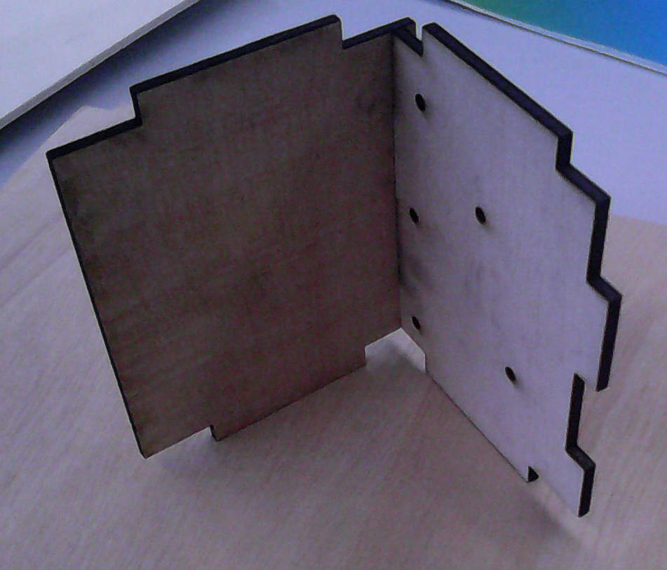
Testing the part fitting, in this case two major components of the Z-Axis assembly.
The tool for testing pulleys assemblies, my brainchild!
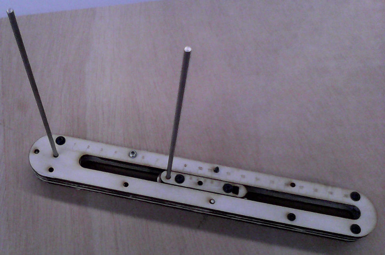
Taking measures for a given assembly, a nonio working in its full beauty.

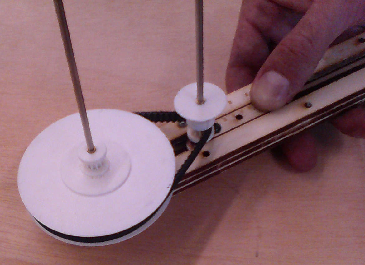
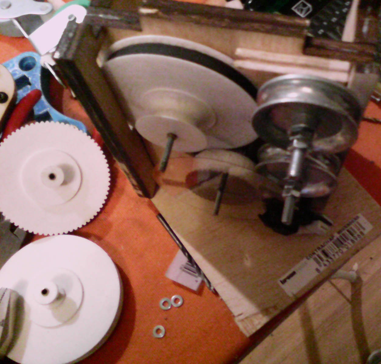
The encoder assembly with a mock disk, together with the traction and guiding pulleys.

Top view of the same assembly, the rubber belt connecting the traction pulley to the encoder's clearly visible.
From another angle.
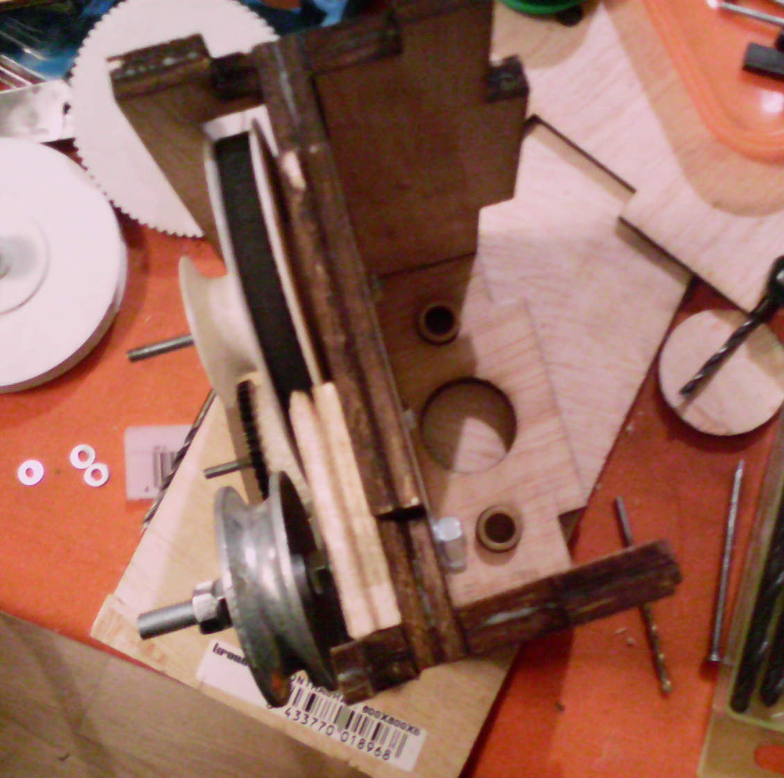
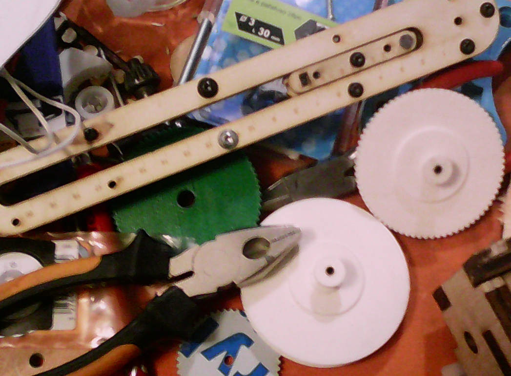
Pulleys, cogs, pliers and all. The joy of building something.
And finally, the moment we were all wainting for... IT MOVES!
In terms of positioning acuracy by combining the metric encoder disc's 1800 steps per revolution and the associated software developed on the week of Interface and Application (x4) with the multiplying effect of the pulley assembly (x4) and a 20mm diameter wheel drived by a fixed cable, theoreticaly it is possible to get an acuracy of 0.002mm.
Acuracy = 20 x PI / ( 1800 x 4 x 4 ) = 0.002 mm
see https://drive.google.com/folderview?id=0B-zSpF8Sy3QLM0pIZmw4c1lRb1k&usp=sharing for files
Guilherme Moreira | 18-01-2014 | 04:46 AM | Lisboa | Portugal | para Fab Academy 2014 (pt)