Building a 3d model on rhino5 of an axis head to run some tests
A longtime ago I’ve learned rhino at school and that’s the reason I used it for these task.
First I started by drawing a circle , than using offset curve
 I drew more concentric circles that I copied to a certain distance, by making a line
  and using mirror
  in the mid point of that line. From there i made more horizontal and vertical lines using some of the above tools, and used trim
  to take out the some parts off the lines leaving behind just some out lines do extrude my model.
Press Fit
I started my press fit task based on a triangle as base material I used some old 3mm acrylic from a store front.
2nd - some basic ideas I already have in mind…( at this point everything is changeable):
Motors - I intend to use dc motors for many reasons, the 1st one being they are more common, then it's easier to buy a used powerful one. And, as I recovered many encoders from hp printers, I can get the proper positioning feedback I need; and the 2nd reason is that I'm going to learn how to read and control input and output devices, nothing better than combine them both on my final project. With hi-torque, both stopped and in motion, good gear reduction, hi-durability and being available as cheap used parts, I found car window and windscreen wiper motors to be apparently ideal for my project…
electronics production


For starters, these weeks don't involve much creativity or own decisions and it's more king of a follow-the-instructions ikea thing, although interesting, as it made me build my first electronics ever.
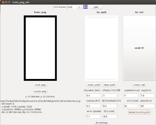
First, using my dear old friend modela mdx 20, which I think would have much to gain if it could use her small I-Modela sister's software (),but this time using fab modules cad.py (in ubunto) which I found to be pretty user-friendly.
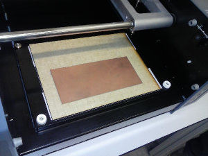
Whith ubunto and fab modules already installed on my computer, I started by opening cad.py whith the icon then placed the board on the machine table (previously protected with a sacrificial MDF board ) using doble-sided tape to fix it and the laser marked grid on the mdf as guide. Then it was time to open the following png in cad.py

Then, because I was using a different machine bit than the one on the default definitions I had to change them and to make a cleaner and more defined pcb I changed the offsets def. to 4 and diameter to 1,5 From there I found my work-0 x,y cad.py and z at modela, made the tool path with "make path" and "make.rml" and hit "send it".
the same was made for both png changing to 3d settings for de interior one and using equals work-0s.
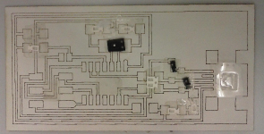
Pbc made, then came the soldering part which was surprising easy for a first timer, with some help from the de-solder quick braid. To be sure I did not misplace some component I made a larger printing of the png no cardboard using the laser machine and pre-taped the components in the designated place.
Whem checking the circuit I notice some bad soldering I had to correct. The programming part was also easy, just followed the instructions on this link http://academy.cba.mit.edu/content/tutorials/akf/programming_FabISP.html#windows and it was ready.
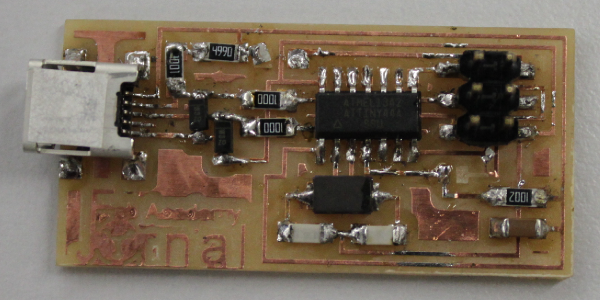
When de-soldering the programming bridges I was a bit precipitated and lifted up a little of the trace luckily I stopped just in time.
see https://drive.google.com/folderview?id=0B-zSpF8Sy3QLM0pIZmw4c1lRb1k&usp=sharing for files
see https://drive.google.com/folderview?id=0B-zSpF8Sy3QLM0pIZmw4c1lRb1k&usp=sharing for files