Building a 3d model on rhino5 of an axis head to run some tests
A longtime ago I’ve learned rhino at school and that’s the reason I used it for these task.
First I started by drawing a circle , than using offset curve
 I drew more concentric circles that I copied to a certain distance, by making a line
  and using mirror
  in the mid point of that line. From there i made more horizontal and vertical lines using some of the above tools, and used trim
  to take out the some parts off the lines leaving behind just some out lines do extrude my model.
Press Fit
I started my press fit task based on a triangle as base material I used some old 3mm acrylic from a store front.
2nd - some basic ideas I already have in mind…( at this point everything is changeable):
Motors - I intend to use dc motors for many reasons, the 1st one being they are more common, then it's easier to buy a used powerful one. And, as I recovered many encoders from hp printers, I can get the proper positioning feedback I need; and the 2nd reason is that I'm going to learn how to read and control input and output devices, nothing better than combine them both on my final project. With hi-torque, both stopped and in motion, good gear reduction, hi-durability and being available as cheap used parts, I found car window and windscreen wiper motors to be apparently ideal for my project…
Hello once again
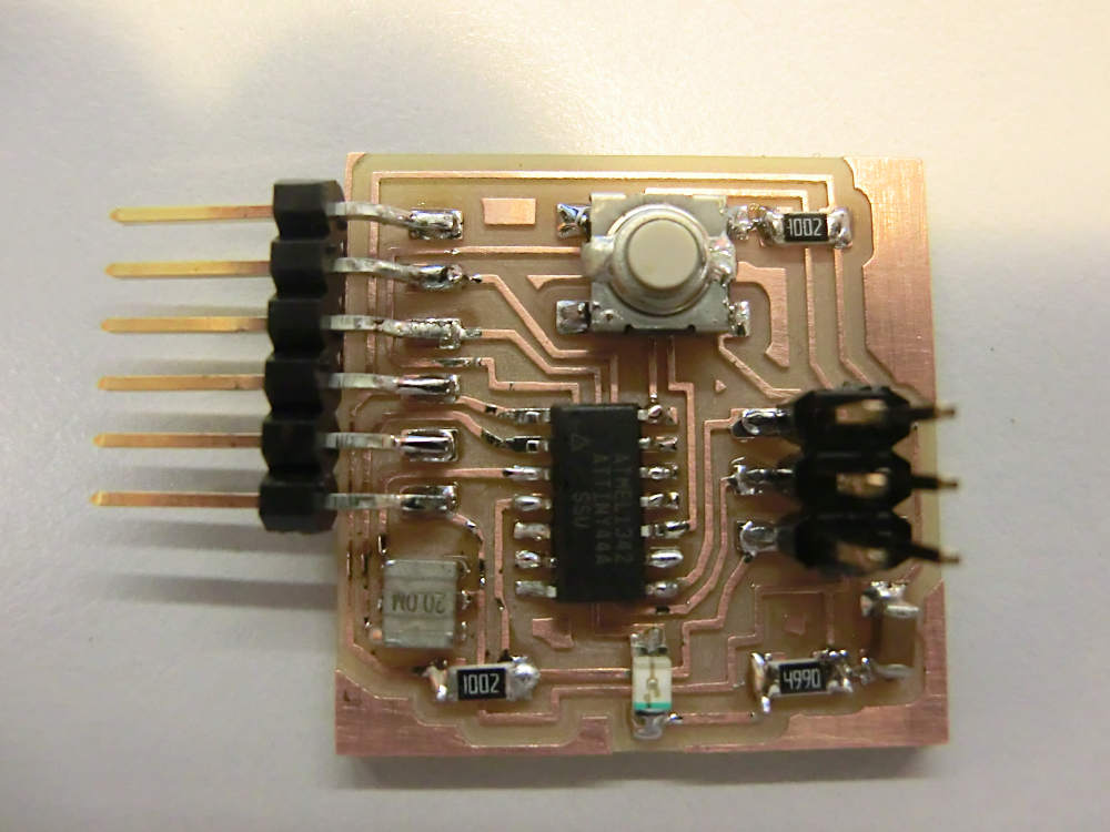
So we are on fab academy seventh week and with another hello board as task. This time we will not only need to build it but we also need to add led and bottom to it, to make it possible, we will have to redraw it, but first lets take a look on what we know so far .
on the original board 5 of theATtiny44A the pins are unconnected, we have a bottom and a led to add to the board ,so we will use 2 of those 5 pins, I chose pa2 and pa3. The led is only 1.8V /10mA so it will need a 330ohm (or the closest I have in this case, 499ohm) resistor to deal with the 5v usb output voltage, in the bottom I will add a 10k resistor to prevent burning the microcontroler,it is also important to understand that the capacitor connecting vcc to gnd, and already present in the board, has the only purpose of stabilizing the current, preventing spikes .
With that in mind, it's time to chose a board design software, Eagle in my case .
Once on eagle I started by updating the libraries with the ones from fab academy and adafruit like suggested on some tutorials I saw.
from there with some more tutorials I pulled all the components to my schematic view using the add buttom , from there I made the connections using
  to draw the lines
  to connect them by name and
 To add some description.

Then I changed to board view and started playing with the components moving sets
 and autorouter
 button, then finalize it with some hand corrections
 and routing
 . and end up with this drawing,

Which I transferred to The Gimp to correct color issues and make the outline
Using corp, image/canvas size/mm_ X+1.6 Y+1.6_center_resize,color/ value invert, layer/new layer_white_OK , layer/stack/lower layer, image/merge visible layers_merge,select/all,copy, paste as new image. That gave me two images, I just painted black the traces on one and the surround square on the other and saved them in .png format


From there I machined and weld the pcb with Modela and a regulative iron just like two weeks ago with hello one
see https://drive.google.com/folderview?id=0B-zSpF8Sy3QLM0pIZmw4c1lRb1k&usp=sharing for files
see https://drive.google.com/folderview?id=0B-zSpF8Sy3QLM0pIZmw4c1lRb1k&usp=sharing for files
Guilherme Moreira | 18-01-2014 | 04:46 AM | Lisboa | Portugal | para Fab Academy 2014 (pt)