12 Interface & Application Programming
Assignment
Make an application. Take a sensor data and present it .
This week I am going to work with Processing language to write an applications for an input device.

Sensor plus Processing
Hello Light Board
For this assignment I will work with the light sensor. I was able to build the Hello Light Board a week ago.

Example Processing Sketches
First I tried run some sketches wrote by Anna K.F and Shawn Wallace. Processing visualisations are great to show a data which is record by the sensor. Plug in to the computer working input device board via FTDI cable. Then run sketch. The input should be shown on the screen. Any interaction with the sensor should change data coming into it and the sketch.
Sketch 1 - Random Lines

/**
* Serial Input to Randomly Colored Lines
*
* Read data from the serial port and changes the color of a lines drawing
* across the screen the height of the lines changes relative to the values
* recieved from the sensor.
*
* written by Shawn Wallace
* updated / commented by Anna Kaziunas France
*/
import processing.serial.*;
Serial serialPort; // Create object from Serial class
int col = 0; //starting point for the lines on the screen
void setup() {
size(1024, 1024); //set window size
background(0); //set background color to black
stroke(255); // set stroke to white
smooth(); //smooth out the lines
// I know that the first port in the serial list on my mac
// is always my FTDI adaptor, so I open Serial.list()[0].
// On Windows machines, this generally opens COM1.
// Open whatever port is the one you're using.
println(Serial.list());
serialPort = new Serial(this, Serial.list()[0], 9600);
}
void draw() {
//if there is data comming in from the serial port
while (serialPort.available () > 0) {
//set the variable height equal to the data comming in.
int height = serialPort.read();
//to draw rows across the screen in columns
//then wrap back to other side of the screen
col = col+1;
if (col > 1024) {
col = 0;
}
println(height); //print the values read from the serial port to the console
//if the serial values are greater than 10
if (height > 10) {
//draw a line that increases / decreases based on sensor output.
//adjusted for sensor values.
line(col, (height-125)+512, col, 512-height);
}
//EXPERIMENT WITH THE VISUALIZATION BELOW
//currently draws random strokes for the full range of color
stroke((int)random(255), (int)random(255), (int)random(255));
}
}
Sketch 2 - Circles

/**
* Phototransistor Input to Circle
*
* Read data from the serial port and changes the fill and stroke color of a circle
* relative to the values recieved from the sensor.
* Circle fill and stroke are random, unless a sensor value below 200 is recived.
*/
//import serial library
import processing.serial.*;
Serial serialPort; // Create object from Serial class
int diameter= 500; // initial diameter of the circle
void setup() {
size(500, 500);
background(0);
stroke(255);
smooth();
// I know that the first port in the serial list on my mac
// is always my FTDI adaptor, so I open Serial.list()[0].
// On Windows machines, this generally opens COM1.
// Open whatever port is the one you're using.
println(Serial.list());
serialPort = new Serial(this, Serial.list()[0], 9600);
}
void draw() {
//filter out the 1,2,3,4 framing code numbers
while (serialPort.available () > 4) {
int lightIn = serialPort.read();
//if the sensor value is greater than 200
//(you may need to tweak this number to get the code to respond to your board)
if (lightIn > 200) {
//print in the sensor values to the console
println(lightIn);
//set the variable diameter to the sensor value
diameter = lightIn;
//use the sensor value to draw an ellipse
ellipse(250, 250, diameter, diameter);
//redraw the screen
redraw();
}
}
//EXPERIMENT WITH THE VISUALIZATION BELOW
//if the sensor values are less that 200, the elipse with random stroke and fill colors
stroke((int)random(255), (int)random(255), (int)random(255));
fill((int)random(255), (int)random(255), (int)random(255));
}
Sketch 3
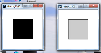
Black square when sensor is exposed and grey when it is covered
/**
* Simple Read - Combined with Neil Gershenfeld's hello.light.45.py
* http://academy.cba.mit.edu/classes/input_devices/light/hello.light.45.py
* adjusted values pulled from Neil's python visualazition program to make
* sense of high and low readings.
*
* Read data from the serial port and change the color of a rectangle
* when the phototransistor connected to the hello light board is receiving
* varing levels of light.
* This example works with the Wiring / Arduino program that follows below.
*/
import processing.serial.*;
Serial myPort; // Create object from Serial class
int val; // Data received from the serial port
int sensorData; // Data recieved from the serial port with 1,2,3,4 framing numbers filtered out
int highVal; //high value read in from Neil's C code
int lowVal; //low value read in from Neil's C code
int actualVal; // adjusted sensor value
void setup()
{
size(200, 200);
// I know that the first port in the serial list on my mac
// is always my FTDI adaptor, so I open Serial.list()[0].
// On Windows machines, this generally opens COM1.
// Open whatever port is the one you're using.
String portName = Serial.list()[0];
myPort = new Serial(this, portName, 9600);
}
void draw()
{
if (myPort.available() > 0) { // If data is available
val = myPort.read(); // read it and store it in val
if (val > 4) { // Filter out the framing numbers: 1,2,3,4
highVal = myPort.read(); // read the high value sent from sensor and store it
lowVal = myPort.read(); // read low value from sensor it and store it
actualVal = 256 * (highVal + lowVal); // getting the actual value of the sensor
println("The actualVal is " + actualVal); //print to the screen
}
//EXPERIMENT WITH THE VISUALIZATION BELOW
background(255); // Set background to white
//READ VALUE BEING PRINTED IN
//ADJUST THE VALUE AFTER THE <
//If you are not getting changes in the visualization in response to changes in the sensor
if (actualVal < 1024) { // If the sensor value is less than a this number
fill(0); // set fill to black
}
else { // otherwise....
fill(204); // set fill to light gray
}
rect(50, 50, 100, 100);
}
}
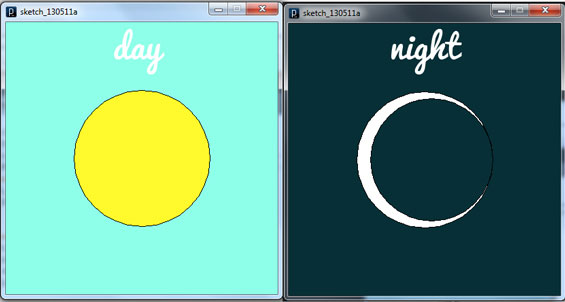
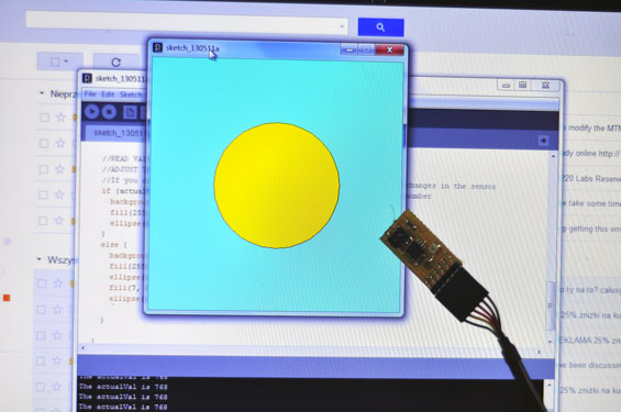
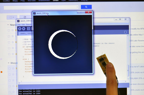
Customizing the sketch
I took and modified thiird sketch. In my visualisation you can see the simply image of the day when the sensore is exposed and the night - when it is covered.
and here is my code:
/**
* Simple Read - Combined with Neil Gershenfeld's hello.light.45.py
* http://academy.cba.mit.edu/classes/input_devices/light/hello.light.45.py
* adjusted values pulled from Neil's python visualazition program to make
* sense of high and low readings.
*
* Read data from the serial port and change the color of a rectangle
* when the phototransistor connected to the hello light board is receiving
* varing levels of light.
* This example works with the Wiring / Arduino program that follows below.
*/
import processing.serial.*;
Serial myPort; // Create object from Serial class
int val; // Data received from the serial port
int sensorData; // Data recieved from the serial port with 1,2,3,4 framing numbers filtered out
int highVal; //high value read in from Neil's C code
int lowVal; //low value read in from Neil's C code
int actualVal; // adjusted sensor value
void setup()
{
size(400, 400);
// I know that the first port in the serial list on my mac
// is always my FTDI adaptor, so I open Serial.list()[0].
// On Windows machines, this generally opens COM1.
// Open whatever port is the one you're using.
String portName = Serial.list()[0];
myPort = new Serial(this, portName, 9600);
}
void draw()
{
if (myPort.available() > 0) { // If data is available
val = myPort.read(); // read it and store it in val
if (val > 4) { // Filter out the framing numbers: 1,2,3,4
highVal = myPort.read(); // read the high value sent from sensor and store it
lowVal = myPort.read(); // read low value from sensor it and store it
actualVal = 256 * (highVal + lowVal); // getting the actual value of the sensor
println("The actualVal is " + actualVal); //print to the screen
}
//EXPERIMENT WITH THE VISUALIZATION BELOW
// Set background to white
//READ VALUE BEING PRINTED IN
//ADJUST THE VALUE AFTER THE <
//If you are not getting changes in the visualization in response to changes in the sensor
if (actualVal < 800) { // If the sensor value is less than a this number
background(142, 255, 233);
fill(255, 249, 44); // set fill to black
ellipse(200, 200, 200, 200);
}
else { // otherwise....
background(7, 47, 54);
fill(255); // set fill to light gray
ellipse(200, 200, 200, 200);
fill(7, 47, 54);
ellipse(210, 200, 180, 180);
}
}
}

