


Final project
Trigeneration
My idea is to generate heat, cold and electricity from a wood fire.
Since the device is supposed to be small and portable, it could be called “Micro-Trigenerator”.
If the stove had an exhaust pipe, it could be used for heating as well.
For generating electricity I would try to use Peltier-Elements as thermoelectric generators. Even though their efficiency is quite low, they should be able to generate a few watts for charging cellphones or illumination.
For producing cold, I would make use of the remaining waste-heat for running a sorbtion refrigerator. It would run in a batch-cycle and produce ice in order to keep the fridge cool for a while.
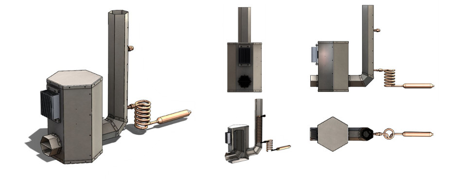
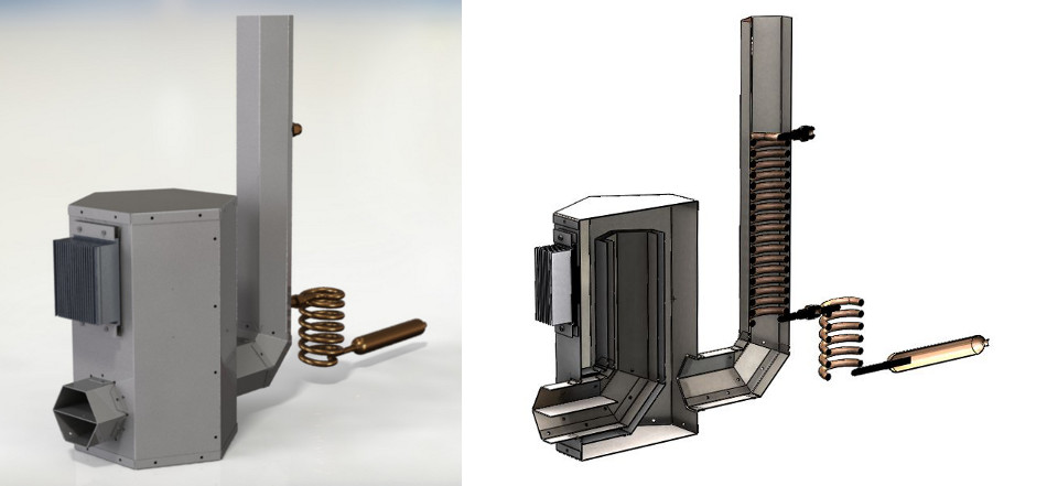
My first conceptual sketch looks like this:
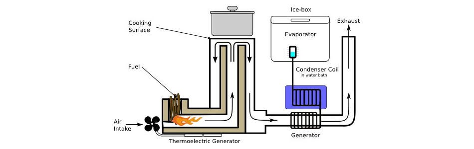
Since most of the parts get quite hot, it won’t be easy to build this in our fablab with limited metal-working tools.
It would be nice to add some electronics for monitoring temperatures and power output.
Update 28.05.2012
By now I have gathered some of the required materials, but I am still too busy with the machine-project to advance a lot with the “Trigeneration”.
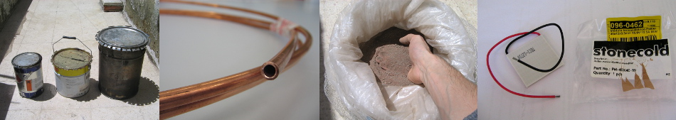
I found some metal buckets that might make some of the first prototypes. I also collected lots of cans that might serve as working material. A copper tube will be used for the generator and the condenser. I wasn’t able to find the right connectors yet, though.
For making a melting furnace I bought some fire clay. Since it only came in bags of 25kg I have lots of it now and might try to build something else with it.
Since the Peltier-elements are quite expensive (the cheapest ones at Digikey for 14$; ~20€ for the 40x40 Thermoelectric cooler that I bought) I started with just one. It has a maximum working temperature of 138°C, above which the BiSn solder will probably start to melt. So I will have to pay a lot of attention on not exceeding this temperature.
For controlling the temperature I will use a thermocouple with a little amplifier to read the signal with a microprocessor. For the temperatures around the thermoelectric generator a thermistor would be enough, but I also want to measure inside the stove. I will probably use some kind of heat-pipe for transporting the heat. I might either try one from an old Laptop or try to fabricate one using the copper tube with water or acetone.
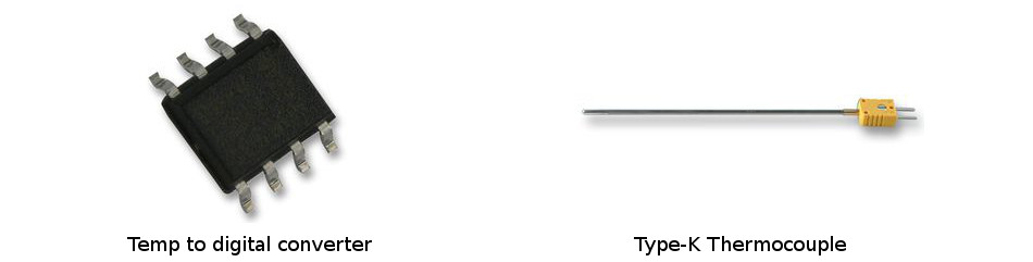
Temperature to digital converter
The voltage from the Peltier element is going to be quite low, so I will try to build a step-up converter (DC-to-DC power converter) for charging a battery. It might be interesting to use an Attiny to control a transistor with a coil, that generates the desired voltage.
For the cooling I will try methanol with activated coal, or water with silica-gel (that I’m starting to get a lot of with all the electronic components ;-)
I still don’t know how I will build the heat exchanger, but I will probably improvise something with the copper tube.
interesting read: designed.mit.edu - Adsorption fridge
Update 27.07.2012
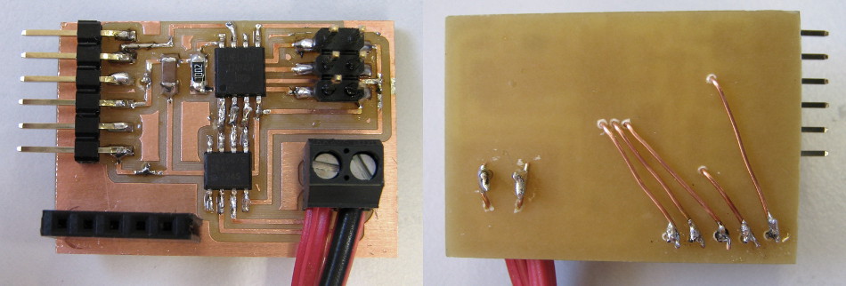
I made a board for the MAX6675 temp-to-digital-converter with an Attiny-45 (eagle-files). I adapted the code from itdaniher to my pin-layout, but I don’t receive anything by serial.
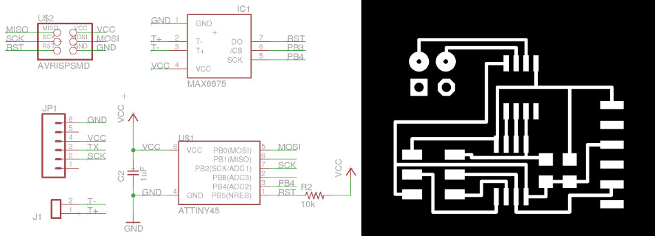
After a lot of unsuccessful debugging I added another header to the board, so can read the MAX6675 with an Arduino and the MAX6675 library. I simply drilled some holes to the corresponding tracks and soldered some wires to the header on the back side. Maybe not the tidiest way, but it works! Any help in getting the Attiny-45 to work is highly welcome! (thermocouple.zip includes code and eagle layout)
For using the MAX6675 library had to do the following:
copy MAX6675.h and MAX6675.cpp into sketchbook/libraries/max6675/
I was getting an error about a missing Wpgroam.h
So in both Max6675.h and max6675.cpp change Wpgroam.h to Arduino.h open single “single_temp” example sketch
rename SCK to SCK1 change
MAX6675 temp0(CS0,SO,SCK,units,error);
to
MAX6675 temp0(CS,SO,SCK1,units,error);
I was able to upload but I couldn’t open the serial monitor
I restarted arduino as sudo and saw that for some reason ubuntu creates lock-file in /var/lock/
With
    rm /var/lock/LCK..ttyACM0
    rm /var/lock/LCK..ttyS4
I removed the two and now everything worked.
The only thing left to do was to change units from 0 to 1
int units = 1; // Units to readout temp (0 = ˚F, 1 = ˚C)
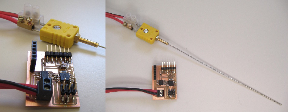
I was surprised that the cheapest thermocouple from farnell came with a connector and a probe. This way I can easily thread the sensor through a hole in the stove and measure temperatures at several points inside.
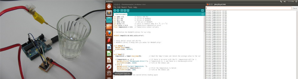
Calibrating the sensor with ice- and boiling water an accuracy of ± 3°C can be achieved, which is in accordance with the datasheet and more than sufficient for my use.
For the design of the stove I followed the recommendations from Aprovecho Research Center, Design Principles for Wood Burning Cook Stoves:
- Insulate around the fire to help it burn hotter. A hotter fire burns up more of the combustible gases and produces less smoke.
- Avoid using heavy, cold materials like earth and sand around the combustion chamber.
- Lift the burning sticks up off the ground so that air can scrape under the sticks and through the charcoal.
- Placing an insulated short chimney above the fire helps to increase draft and gives smoke, air, and fire a place to combine, reducing emissions.
- The combustion chamber chimney should be about three times taller than its diameter.
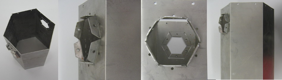
After a lot of brooding I decided to make the stove out of 1mm sheetmetal. Anything thinner would rust away too fast and clay or other molded materials wouldn’t give me the stability I am looking for. Instead of welding I decided to use rivets and a refractory glue for sealing the slots. For the sake of easier construction the body and the ducts are hexagonal instead of round.
It was the first time for me to use the Sheetmetal Workbench in Solidworks. Apart from some bugs with mirroring of bend-features this worked really nice and easy.
In the following drawing you can see the flattened pieces of the stove.
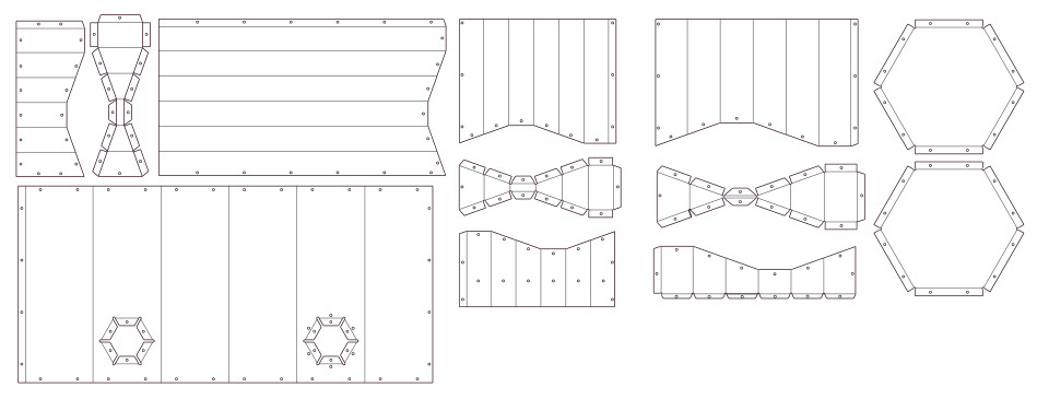
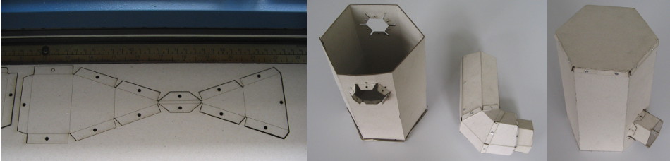
I made a carton-model with the laser-cutter that helped me to get the spacing of the rivets right and confirmed that it is possible to assemble the pieces.
I bought a one by two meter piece of sheet-iron and, due to the lack of time and a car, transported it to the lab by subway (yes, that was a stupid idea! I had sore muscles for two days. Forgive me Lisbon!) Stainless steel would have been a lot nicer but this would have overburdened my budget.
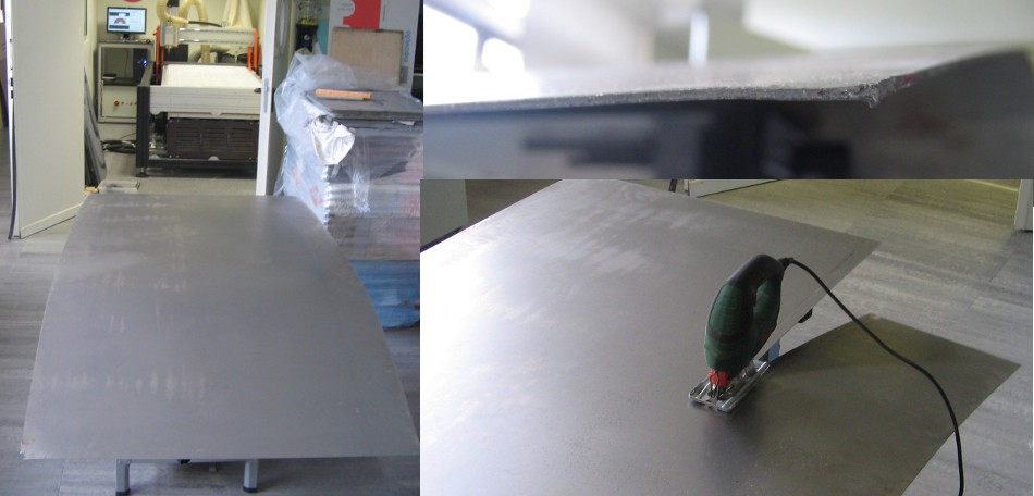
Looking at the piece of steel was quite daunting. It’s big and heavy and 1mm feels thicker than it sounds!
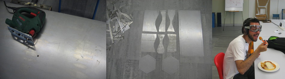
In order to fit it on the milling machine I had to cut a stripe off with a Jigsaw.
The idea was to cut it out with a short and robust 4-blade 3mm HSS-mill that I bought for 7€ in a local store. For cooling I prepared an emulsion with milk and oil. I destroyed the mill completely with the first plunge into the material. Probably I was a bit too reluctant with the z-feed-rate and had a too high spindle speed, so the mill just overheated and melted to the steel. Rolled sheet metal also probably isn’t the easiest material to mill since it has a lot of strain hardening.
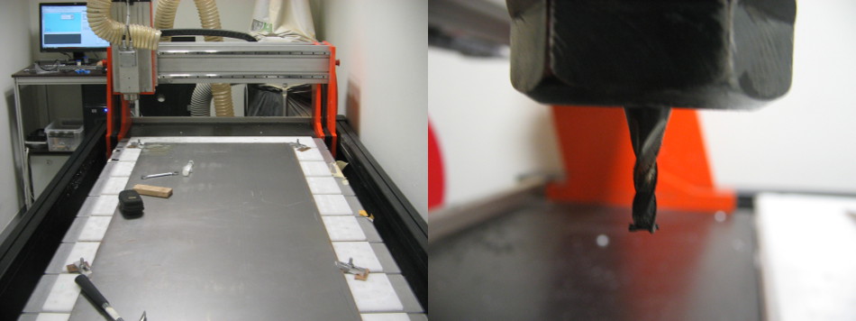
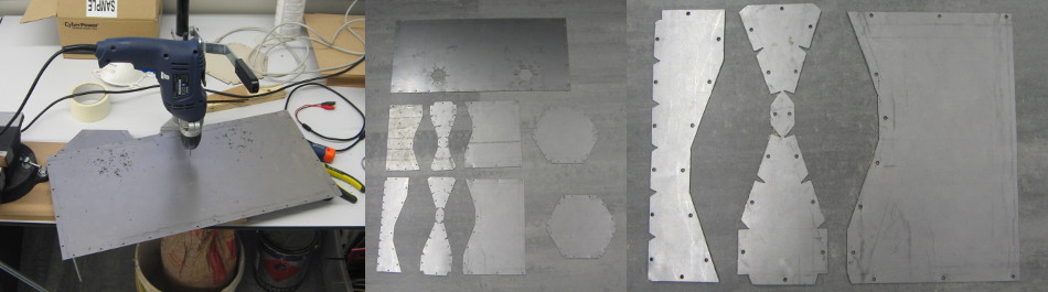
I gave up on the milling idea and decided to continue with the Jigsaw. In order to get the design onto the metal I built a little engraving-tip. I switched the controller of the mill to manual mode and turned the rotation off in order to scratch the drawing onto the metal.
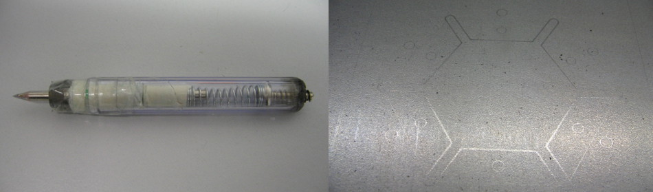
Cutting the pieces with the Jigsaw worked really well but is very loud. Always wear your eye and ear-protection, wherever and whenever somebody is cutting steel with a Jigsaw! Thanks to Luis (right) for withstanding the noise!
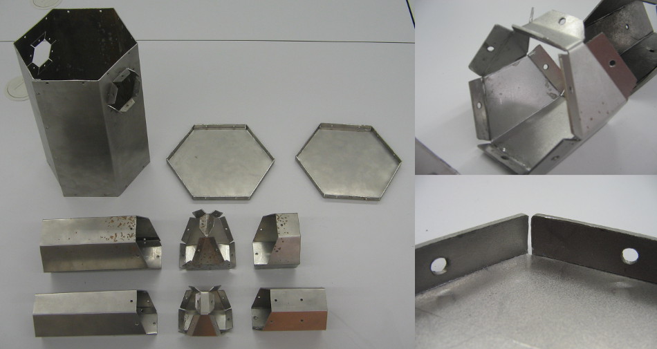
After cutting out the last details and drilling the rivet-holes I had the first set of pieces to start bending.
In order to facilitate the bending I reduced the material strength at the fold with a metal-cutting disk. For getting the straight lines right, I built a little adapter for the rotary-tool for working with a guidance.
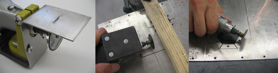
I improvised a little bending apparatus with two L-profiles and door-hinges on a wooden base. Now I know that I should have invested some more money for getting the next bigger steel-profile and a metal base. The profile is bending (!) and the forces deform the wood where the screws are fixed. The principle works fine though and was sufficient for bending the pieces.
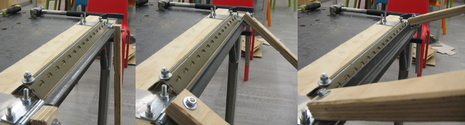
In the pictures below you can see the steps for bending the main body. I used a piece of cardboard for measuring the angle.
For the ducts I had to bend the L-profile a bit for fitting it inside at the last bend.
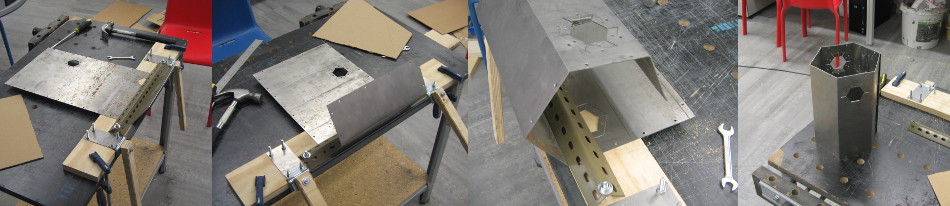
The other pieces worked in the same manner, apart from the hole in the body, where I just used some pliers to bend out the flaps.
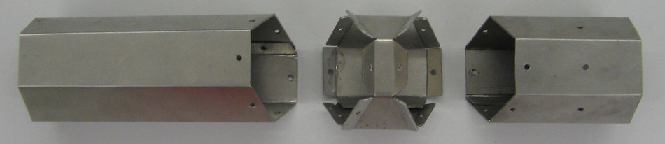
Since I had spent a lot of time for preparing the folds the bending went quite quick and easy and I was ready to start riveting!
Riveting is quick but hard to undo. The idea to use sheet-metal screws came too late but will probably be revisited after drilling open the first rivets.
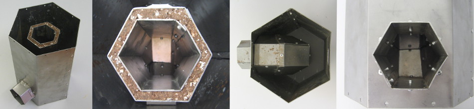
For the insulation of the chimney I used a mixture of fire-clay and Perlite. Thanks to Tiago from the Hackerspace in Montemor-o-Novo for this excellent recommendation!
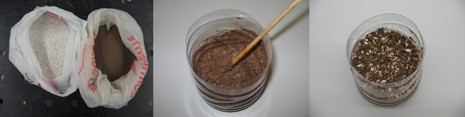
The insulation was inserted between the inner and the outer chimney while assembling the two parts.
The unit was then riveted into the main body with radial and horizontal rivets.
The top cover was mounted in the same way as all the other pieces with a generous amount of heat resistant glue in the seam.
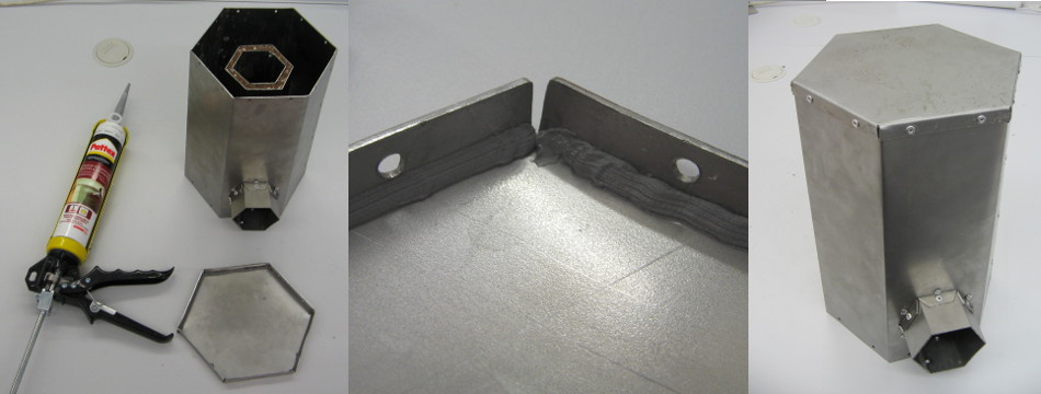
I couldn’t find a place to buy the connectors that would attach the generator to the condenser, so while I was on standby with the stove I started to make a boost-converter on the weekend. The voltage that the peltier-element generates is too low for charging a battery. An easy way of dealing with this problem is buying something like the LiPower from sparkfun. I decided to build one myself with an attiny. I found a great DIY DC/DC Boost Calculator that helped me to dimension the components.
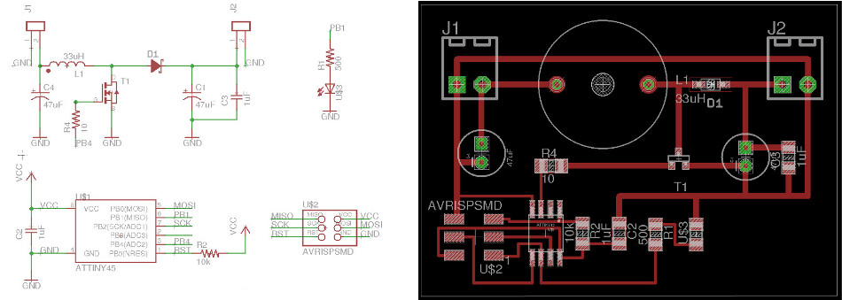
Apart from the capacitors and the inductor (that I found in the electronic trash from altlab) all components are in the fabalab inventory. (eagle-files)
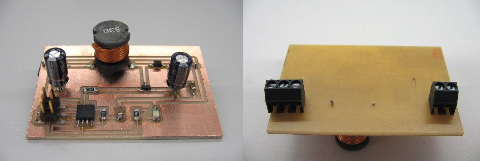
I ran out of 2-pole screw-terminals, so I had to use a 3-pole on one side. This time I soldered everything on top and flipped the terminals to the bottom.
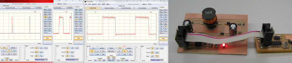
Unfortunately there aren’t any Linux-drivers for our Osciloscope, so this was the first time I programmed the Attiny on Windows 7 64-bit. After installing the driver for the FabISP from Mighty Ohm and WinAVR I was able to program the new circuit with the Arduino IDE.
I started with blinking the LED (changing LED-Pin to 1) and then tested the PWM with “analogWrite”. On the first try (selecting Attiny45 8MHz) I only got a PWM frequency of 55Hz. After selecting Tools —> Burn Bootloader, it went up to 500Hz.
Making the LED fade with PWM on port-A (PWM1A) was easy, but I didn’t get it to work with PWM1B where I had the MOSFET connected.
In the end I switched from Arduino to plain c-code. For getting up to 32150Hz on PWM1B I used the following code:
int main(void) {
    TCCR1|=_BV(CS10);
    TCCR1|=_BV(COM1A0);
    GTCCR|=_BV(PWM1B);
    GTCCR|=_BV(COM1B1)|_BV(COM1B0);
    DDRB|=_BV(PB4);
    OCR1B=0x80;
    while(1){}
}
Here are some interesting pages for learning about Bit_manipulation: Wikipedia, AVRfreaks
On the first try I generated 42V at a duty cycle of 60%! Later I realized that this voltage quickly breaks down as soon as I connect a load.
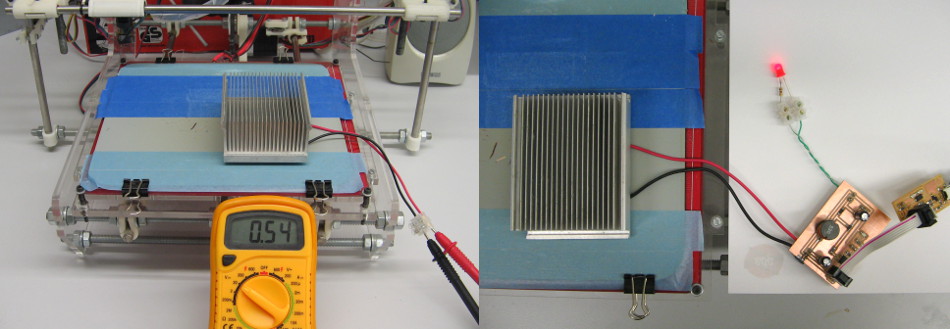
In the following video you can see me running a 12V-fan with an old battery that only went up to 0,9V. I didn’t have a battery holder, but thanks to pictux and our “Prusa Air 2”, this was quickly resolved!
I tested the peltier with the boost converter on the heated build platform of our 3D-printer. At 110°C the peltier generates an open-circuit voltage of 0.5V. With the boost-converter and an LED as load, I measured 5V at the output. So in theory it should be possible to charge a cellphone or any other “USB-compatible” device like this.
After the weekend I finally found a place to buy the connectors ARL. Air-conditioning-shops was the way to go!
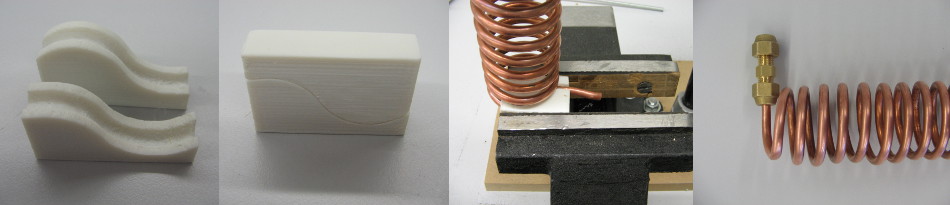
The next task was to bend the tube into a spiral. For facilitating this, I quickly modeled and printed a little tool that would bend the tube with the right pitch and diameter:
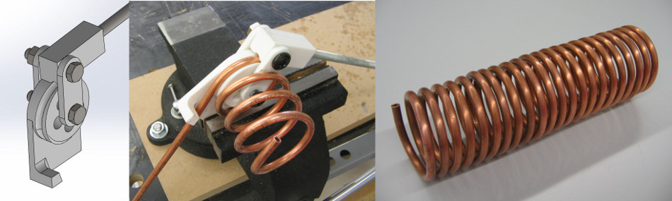
This worked really well. The diameter ended up a bit too big, but I found a pole on the parking lot, with the right diameter, that helped me to twist it down to the right size.
The next problem was the double-bend at the end of the tube. Another little 3D-printed gadget helped me to get this right:
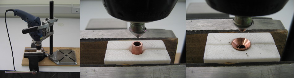
For using the hydraulic connectors, the tube has to have a flared end. There are special tools for making flare fittings, but since they are quite expensive and I failed to borrow one, I made one myself. The die that grips the tube was 3D-printed and the mandrel was fabricated from a M8 screw.
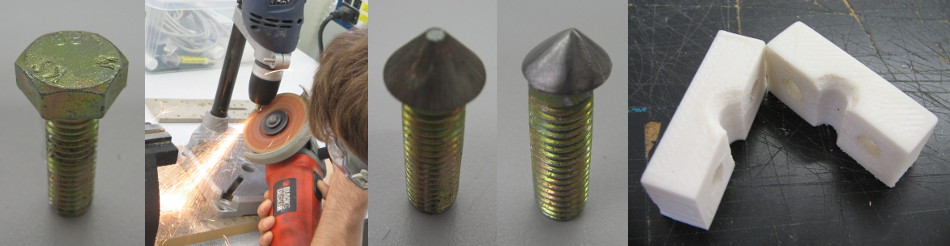
The first step was to give the bolt-head a conical shape. My version of “Afghan-lathe” with a drill rig and an angle grinder probably isn’t the most decent way of accomplishing this, but it works. The idea was to give the bolt head an off-centered shape, for increasing the compression stress to the tube, and then open the tube with each turn a little bit. Unfortunately the construcion for getting the drill over the vice wasn’t stiff enough, but using the “roto hammer-mode” I was able to make some beautiful flared ends.
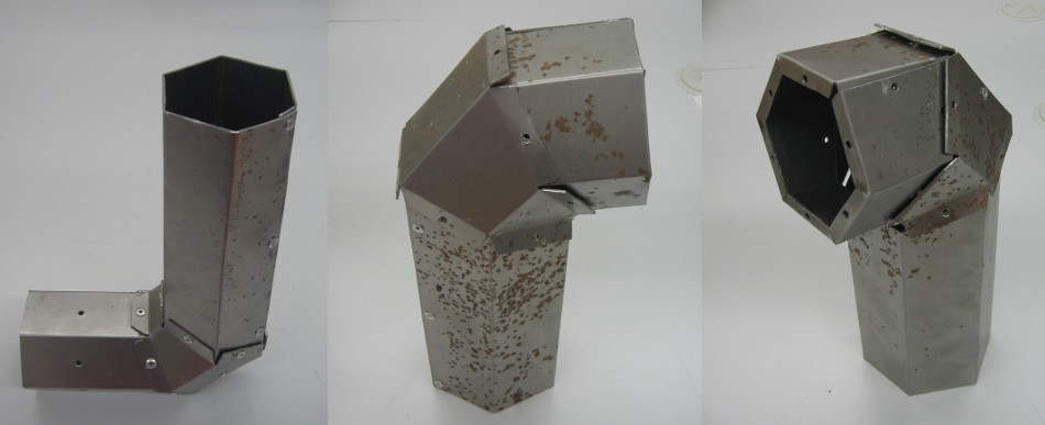
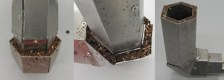
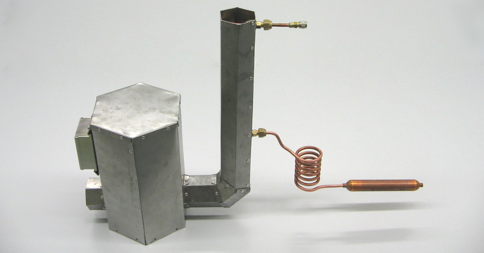
Finally I was able to close the chimney with the tube inside and attach it to the body of the stove.
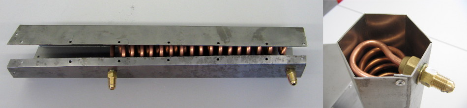
For mounting the thermoelectric generator with the dissipater on the stove I riveted two extra pieces of sheetmetal on each side. They are supposed to keep the screws for the heatsink from getting hot by direct heat conduction.
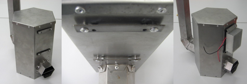
Below you can see the first (almost) complete assembly. It is still missing the cap on the bottom and a box for the fridge.
After riveting the bottom it was time for the first test of the stove. I didn’t install the Peltier-element yet, because I was afraid that I might surpass the 138°C temperature limit and destroy the module. Equipped with the temperature sensor and an IR-camera I went to cook some pasta!
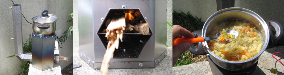
To my big relief the stove worked perfectly! I thought that I might have to help a bit with a fan in order to get the first flow right, but after some initial problems with lot’s of wind the stove started quickly and boiled a liter of water in under 10min. For cooking the pasta and making all the measurements I only used one piece of pine wood of about 20x100x300mm.
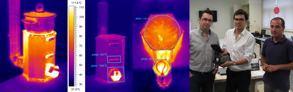
Thanks to our neighbors at Labelec from the Thermography-Department, I have some images in Infrared-spectrum from the stove in action. Thank you! The temperature at the peltier-mount-point doesn’t seem to surpass the 138°C, but the screws for the heat-sink seem to get too hot. I still don’t understand this completely. From the [tempering color] it looks like the steel has been above 300°C. I also found some more interesting details, like hot-spots on the surface, that I will still have to study in more detail.
I will have to do some more tests before putting the Thermoelectric-generator and the Adsorption-fridge to work, but so far I am very satisfied with the results.
Below you can see a video of the first test-run.