Week18
- Project Development
Final project development records
June 11-13 Slide and Movie for presentation
Preparation of a slide and a movie for the presentation on June 14th.
I am not familiar with video editor softwares. Since I didn’t know that HEIC format files cannot handle in the editor, I tried and had errors so many times. Then gave up and tried to use Microsoft power point for making a movie.
Yes, I could include movies in slides but once it went to slide show to record, it stopped and not moved to next slide and replayed as I expected.
Thanks for my instructor’s suggestions, somehow I created a final presentation video by iMovie.
June 8 Tested Final project item in Final package and took movies
- Add tire houses for smooth moving of wheels because the edge of the Skull touched Wheels
- Put furry outfit on Skull. Due to this, necessary to adjust sensitivity of sound sensors because they were inside of the thick fake coat.
- Made adjustments of direction of sound sensors after putting the skull.
- Put mats on the floor so that acrylic wheels had torque of DC motors better.
- Tied jumper codes tidy


June 3 - 5 Solved remaining problems
- Put a Heat sink on motor driver since it became so hot during tests
- changed version of MegaTinycore board manager to 2.2.6, 2.2.9 which was told as stable but not work for me.
- Sound sensors might catch the noise of DC motors like claps. Needed to know the impact to movements. I hope the thick coat prevent it.
- Finalized the program.
- Brand-new sound sensors
- Sewing furry outfit
- Made tails longer than that of the proto type so that it appeared after putting the skull and the outfit on the body.
Acrylic wheels slipped on the floor.
#include <Servo_megaTinyCore.h>
//#include <Servo.h>

Servo myservo;       // create servo object to control a servo


int leftDC1   = 0;
int rightDC1  = 1;
int leftDC2  = 8;
int rightDC2  = 9;
int pos = 90;    // variable to store the servo position

const int rightSensorPin=15;
const int leftSensorPin=16;
boolean rightVal = 0;
boolean leftVal = 0;

void movetail(){
  for (pos = 90; pos <= 180; pos += 1) { // goes from 90 degrees to 180 degrees
    // in steps of 1 degree
    myservo.write(pos);              // tell servo to go to position in variable 'pos'
    delay(15);                       // waits 15ms for the servo to reach the position
  }
  for (pos = 180; pos >= 0; pos -= 1) { // goes from 180 degrees to 0 degrees
    myservo.write(pos);              // tell servo to go to position in variable 'pos'
    delay(15);                       // waits 15ms for the servo to reach the position
  }
   for (pos = 0; pos <= 90; pos += 1) { // goes from 0 degrees to 90 degrees
    // in steps of 1 degree
    myservo.write(pos);              // tell servo to go to position in variable 'pos'
    delay(15);                       // waits 15ms for the servo to reach the position
  }

}

void moveForward(){
  digitalWrite(rightDC1, LOW);
  digitalWrite(leftDC1, HIGH);
  digitalWrite(rightDC2, LOW);
  digitalWrite(leftDC2, HIGH);
}

void moveBack(){
  digitalWrite(leftDC1, LOW);
  digitalWrite(rightDC1, HIGH);
  digitalWrite(leftDC2, LOW);
  digitalWrite(rightDC2 , HIGH);
}

void moveStop(){
  digitalWrite(rightDC1, LOW);
  digitalWrite(leftDC1, LOW);
  digitalWrite(rightDC2, LOW);
  digitalWrite(leftDC2, LOW);
}

void turnLeft(){
  digitalWrite(rightDC1, LOW);
  digitalWrite(leftDC1, HIGH);
  digitalWrite(rightDC2, HIGH);
  digitalWrite(leftDC2, LOW);
}

void turnRight(){
  digitalWrite(rightDC1, HIGH);
  digitalWrite(leftDC1, LOW);
  digitalWrite(rightDC2, LOW);
  digitalWrite(leftDC2, HIGH);
}

void setup() {
  pinMode(leftDC1, OUTPUT);
  pinMode(rightDC1, OUTPUT);
  pinMode(leftDC2, OUTPUT);
  pinMode(rightDC2, OUTPUT);
  myservo.attach(10);   //attaches the servo on pin 10 to the servo object


  pinMode(leftSensorPin, INPUT); //pin 16 an input pin.
  pinMode(rightSensorPin, INPUT); //pin 15 an input pin.

  Serial.begin(9600);// initialize the serial port:
}
void loop() {

  //poll inputs for signal
  rightVal =digitalRead(rightSensorPin);
  leftVal =digitalRead(leftSensorPin);

     // when the sensor detects a signal above the threshold value set on sensor, turn finder to the direction of sound
  if (leftVal==LOW && rightVal==HIGH)
  {

  Serial.println("turn right");
  turnRight();
  delay(1000);

 }
  else if (leftVal==HIGH && rightVal==LOW)
  {

  Serial.println("turn left");
  turnLeft();
  delay(1000);
 }
  else if (leftVal==LOW && rightVal==LOW)
  {
  Serial.println("stop");
  moveStop();
  delay(1000);
  movetail();
  }

   else if (leftVal==HIGH && rightVal==HIGH)
  {

  Serial.println("move forward");
  moveForward();
  delay(1000);
 }

}
June 1 Found new problems
- The programs have been already passed tests by part But didn’t work well today..
- Re-tried part tests and finally figured out that sound sensors were broken.
- Also found out mobile battery packs broken.
- changed from mobile battery back to AA dry cells.
- for IC and servo, 3 cells
- for DC motors, 4 cells
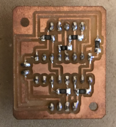
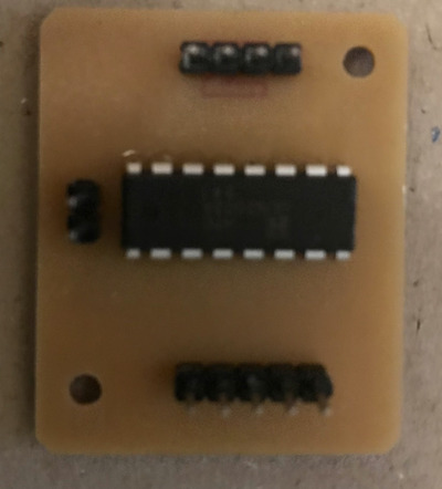
May 29 Motor Driver DRV 8835 for DC Motors test and made a circuit board for final project, and 3D printed servo motor holder to fix it on body case.
I made a circuit board for Final project item, which included ATtiny 3216 and DRV8835. Placed holes to nail it on the body case.
Eagle files of Final circuit board
Test new board with Sound sensors
// Turn speed range(35-255)
// larger number is turn quicker
const uint8_t speeds = 100;

const int rightSensorPin=15;
const int leftSensorPin=16;
boolean rightVal = 0;
boolean leftVal = 0;


void setup() {

  pinMode(leftSensorPin, INPUT); //pin 16 an input pin.
  pinMode(rightSensorPin, INPUT); //pin 15 an input pin.


  Serial.begin(9600); // initialize the serial port:
}

void loop() {
  //poll inputs for signal
  rightVal =digitalRead(rightSensorPin);
  leftVal =digitalRead(leftSensorPin);

   // when the sensor detects a signal above the threshold value set on sensor, turn finder to the direction of sound
   if (leftVal==LOW && rightVal==HIGH){
       Serial.println("turn right");

        // clockwise
        Serial.println("clockwise");
        analogWrite(0,speeds);
        analogWrite(1,0);

        analogWrite(8,0);
        analogWrite(9,speeds);

        delay(1000);
        }
   else if (leftVal==HIGH && rightVal==LOW){
        Serial.println("turn left");

        // counterclockwise
        Serial.println("counterclockwise");
        analogWrite(0,0);
        analogWrite(1,speeds);

        analogWrite(8,speeds);
        analogWrite(9,0);

        delay(1000);
        }

  else if (leftVal==LOW && rightVal==LOW){

        Serial.println("Stop");
        analogWrite(0,0);
        analogWrite(1,0);

        analogWrite(8,0);
        analogWrite(9,0);

        delay(10000);

        }

   else if (leftVal==HIGH && rightVal==HIGH){

        Serial.println("Go");
        analogWrite(0,speeds);
        analogWrite(1,0);

        analogWrite(8,speeds);
        analogWrite(9,0);

        delay(10000);

        }
   }
May 28 Composite Skull and servo motor library tests
I worked on composite process with my instructors to make a skull.
Composite
- Designed a round shape in Fusion
- Installed Slicer for Fusion add-on from site
- Selected Tools then Slicer for Fusion to export to data from Fusion to Slicer.
- Selected type of Slice = interlocked slices
- Selected get plan
- Changed file type to export as DXF then export to my PC
- Import the data to Corel Draw and print
- Cut card boards by laser cutter
- Assembled the card boards
- Covered it with a vinyl bag
- Laser cut Burlap ref
- Covered desks to prevent from becoming dirty
- Put safety glasses, opened windows and put gloves for safety
- Mixed Polyester resin base and 2% of Catalyst
- Dipped Burlap in the mixed base and put it on the skull quickly. Hardening starts in 30 min after mixing.
- Put mylar sheet(making small holes on vinyl bag ) on it.
- Put kitchen papers on it
- Put it in vacuum storage bag and vacuum by cleaner.
- Waited 24hrs for hardening completed
- Removed materials put on outside
- Removed card boards inside
- Removed excess resins at the edge of the Skull
- Made holes for sound sensors and a Tail


Servo Motor
For Megatiny, there is a liblary.
just #include
Interfacing MG995 55G Metal Gear Servo with Arduino https://electropeak.com/learn/interfacing-towerpro-mg995-55g-metal-gear-servo-with-arduino/

#include <Servo_megaTinyCore.h>
//#include <Servo.h>

Servo myservo;

void setup()
{
myservo.attach(9);
}

void loop()
{
myservo.write(90);   //turn 90 degrees
delay(2000);
myservo.write(20);   //turn 20 degrees
delay(2000);
myservo.write(160);  //turn 160 degrees
delay(2000);
}
May 27 research on DC motor and remake body box and sound sensor box by laseer cutter
- Stepper motor moves very slow.Then did quick research on DC motor and example codes.
Sound Sensor Module with Arduino Tutorial.Clap Switch!!!
- Laser cutter : made smaller size of body boxes for final project item.
fusion files include tail parts
May 26 BOM as of today
Bill of Materials until today.
| Item | Qty | Unit Price | From | Site |
|---|---|---|---|---|
| Servo | 1 piece | 850 | Amazon | https://www.amazon.co.jp/gp/product/B08DCXZK3B/ref=ppx_yo_dt_b_asin_title_o01_s00?ie=UTF8&psc=1 |
| Burlap | Amazon | https://www.amazon.co.jp/-/en/Cotton-Linen-Craft-Fabric-Lengths/dp/B06ZZQLHS8/ref=sr_1_9?dchild=1&keywords=%E9%BA%BB&qid=1621999604&sr=8-9 | ||
| Mobile battery | 2 pack | 2500 | Amazon | https://www.amazon.co.jp/gp/product/B018KD0D82/ref=ppx_yo_dt_b_asin_title_o02_s00?ie=UTF8&psc=1 |
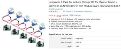
| Stepper Motor | 2 piece | 300 | Amazon | https://www.amazon.co.jp/gp/product/B06XCSCD8T/ref=ppx_yo_dt_b_asin_title_o03_s00?ie=UTF8&psc=1 |
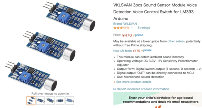
| Sound sensor | 2 piece | 300 | Amazon | https://www.amazon.co.jp/gp/product/B08B857KCP/ref=ppx_yo_dt_b_asin_title_o03_s00?ie=UTF8&psc=1 |
| M3 Screw / Nuts | 1 set | 765 | Amazon | https://www.amazon.co.jp/-/en/uxcell-Cross-Screws-Model-Silver/dp/B01HZCYV3W/ref=sr_1_9?crid=3ST43NIU1F4K3&dchild=1&keywords=m3+%E3%83%8D%E3%82%B8&qid=1622001313&s=industrial&sprefix=M3%2Cindustrial%2C288&sr=1-9 |
May 21 BallCaster
Since Unistep2 can work for 2 stepper motors, I decided to use 2 wheels and add a boll caster.
I referred to below sites for 3D printing data of ball caster.
Other testing results:
- I tried to add servo motor to the program. However the serve motor didn’t move.
- If connected supply to the servo separately, it moved.
- The sound sensor can adjust by potentio meter on it.
- The sensitivity of the sound sensors seems to have cirtain impacts to turn speed of the stepper motors. The stepper motors moved very very slow.
May 20 Unistep2 Library and stepper motor 28BYJ-48 library.
Another solution to move stepper motors together was Unistep2 library. Also we found a library for tepper_28-byj_48.
Unistep2 worked on ATtiny3216 if Analog/Digital pin used. Digital pins didn’t work well. Unistep2 control 2 stepper motors. not work for 4 stepper motors.
#include <Unistep2.h>

// pins for IN1, IN2, IN3, IN4, steps per rev, step delay(in micros)
Unistep2 stepperX(0, 1, 2, 3, 4096, 1000);
Unistep2 stepperY(4, 5, 6, 7, 4096, 1000);


void setup(){
// Your setup code here
  // The library initializes the pins for you
}

void loop(){
 // We need to call run() frequently during loop()
    stepperX.run();
    stepperY.run();

  // Create random movements for the steppers
    if ( stepperX.stepsToGo() == 0 ){ // If stepsToGo returns 0 the stepper is not moving
        stepperX.move(random(-4000,4000));
    }
    if ( stepperY.stepsToGo() == 0 ){
        stepperY.move(random(-4000,4000));
    }
 // Other code
//}

(My UPDI board might have some troblue, encoutered losts of errors and forced restart PC frequently. I could test only a few cases.)
Unistep2.h + Sound sensors
Added sound sensors
Cabling
| Peripheral | t3216pin |
|---|---|
| Stepper 1 | 0,1,2,3 |
| Stepper 2 | 4,5,8,9 |
| Sound sensor -Right | 15 |
| Sound sensor -Left | 16 |
/*
 * Unistep2 example: move
 *
 * Simple example of stepper enumeration and movement via move(steps).
 * If steps > 0 clockwise, else counter clockwise. Non-blocking.
 *
 * 30Jan18
 * R Sanchez
 *
 * This code is released to the public domain
 *
 */

// include the library
#include <Unistep2.h>

// Define some steppers and the pins they will use
Unistep2 stepperX(0, 1, 2, 3, 4096, 1000);
Unistep2 stepperY(4, 5, 8, 9, 4096, 1000);

const int rightSensorPin=15;
const int leftSensorPin=16;
boolean rightVal = 0;
boolean leftVal = 0;


void setup()
{
  pinMode(leftSensorPin, INPUT); //pin 16 an input pin.
  pinMode(rightSensorPin, INPUT); //pin 15 an input pin.

   // initialize the serial port:
  Serial.begin(9600);
}

void loop()
{
  // We need to call run() frequently during loop()
  stepperX.run();
  stepperY.run();

  //poll inputs for signal
  rightVal =digitalRead(rightSensorPin);
  leftVal =digitalRead(leftSensorPin);

   // when the sensor detects a signal above the threshold value set on sensor, turn finder to the direction of sound
  if (leftVal==LOW && rightVal==HIGH){
     Serial.println("clockwise");

     if ( stepperX.stepsToGo() == 0 ){ // If stepsToGo returns 0 the stepper is not moving
     stepperX.move(4000);

     delay(500);            //500ms待つ
     }
  }
 else if (leftVal==HIGH && rightVal==LOW){
      Serial.println("counter-clockwise");

      if ( stepperY.stepsToGo() == 0 ){ // If stepsToGo returns 0 the stepper is not moving
      stepperY.move(4000);

      delay(500);            //500ms待つ
     }
 }
  else if (rightVal == 0 && leftVal == 0 ){
      Serial.println("go forward");

      stepperX.move(4000);
      stepperY.move(-4000);

      delay(500);            //500ms待つ
     }
}

Stepper_28BYJ_48.h
Tested with Arduino UNO per referenced circuit.
#include "Stepper_28BYJ_48.h"


int switch_1_pin = 10;
int switch_2_pin = 12;

Stepper_28BYJ_48 stepper(7,6,5,4);

//////////////////////////////////////////////////////////////////////////////
void setup() {
  pinMode(switch_1_pin,INPUT_PULLUP);
        pinMode(switch_2_pin,INPUT_PULLUP);

}

//////////////////////////////////////////////////////////////////////////////
void loop() {

      if ( digitalRead(switch_1_pin) == LOW ) {
                stepper.step(-1);

        }

        if ( digitalRead(switch_2_pin) == LOW ) {
                stepper.step(1);
        }

}
About torque of Stepper_28BYJ_48, YouTube - Stepper motor 28BYJ-48 torque test
May 19 4 Stepper motors need to move all at once but moved one by one.
2 wire construction has resulted good, but stepper motors turn one by one on ATtiny3216. That is not good since I want 4 wheels altogether to control movement.
My instructor advised me that there is Time Action library.
Preemptive Multitasking Scheduler for AVR Multitasking on AVR
I tried the Time Action library but still moved one by one.
#include <TimedAction.h>
#include <Stepper.h>

//for 2 wire construction 2048 step/ a turn
const int MOTOR_STEPS = 2048;

void stepper2_control();
void stepper3_control();

//TimedAction 関数宣言 = TimedAction(並列処理の間隔, 並列処理用の関数) ;
TimedAction motorAction2 = TimedAction(0,stepper2_control);
//TimedAction motorAction3 = TimedAction(0,stepper3_control);

Stepper myStepper2(MOTOR_STEPS, 2,3);
Stepper myStepper3(MOTOR_STEPS, 4,5);

void setup() {

  myStepper2.setSpeed(10); // 10回転/1分に設定 rpm(1分あたりの回転数)
  myStepper3.setSpeed(10);

  // initialize the serial port:
  Serial.begin(9600);
  }

void loop() {
  motorAction2.check();
 // motorAction3.check();
}

void stepper2_control() {
 Serial.println("2-clockwise");
  myStepper2.step(512);
  myStepper3.step(512);

  delay(100);            //90度回転し1たら500ms待つ

  Serial.println("2-counter-clockwise");
  myStepper2.step(-512);
  myStepper3.step(-512);
}

//void stepper3_control() {
 //Serial.println("3-clockwise");
 // myStepper3.step(512);

  //delay(100);            //90度回転し1たら500ms待つ

  //Serial.println("3-counter-clockwise");
  //myStepper3.step(-512);

//}
May 18 Circuit for Stepper 2 pin mode
Originally each stepper motor use 4 pins of microcontroller circuit. That means I need secure 16 pins for 4 stepper motors to connect 4 wheels. I need 4 pins for 2 sound sensors and 2 pins for servo motor. 22 pins in total.
ATtiny3216 has 20 Pins including GRD and VCC.
My instructor found a solution to this problem.
It’s StepperUnipolarCircuit
ref.


Tried on a bread board the 2 wire construction.
- The sequence of control signals for 2 control wires is as follows
- (columns C1 and C2 from above): *
- Step C0 C1
- 1 0 1
- 2 1 1
- 3 1 0
- 4 0 0
 /*
  * two-wire constructor.
  * Sets which wires should control the motor.
  */
 Stepper::Stepper(int number_of_steps, int motor_pin_1, int motor_pin_2)
 {
   this->step_number = 0;    // which step the motor is on
   this->direction = 0;      // motor direction
   this->last_step_time = 0; // timestamp in us of the last step taken
   this->number_of_steps = number_of_steps; // total number of steps for this motor

   // Arduino pins for the motor control connection:
   this->motor_pin_1 = motor_pin_1;
   this->motor_pin_2 = motor_pin_2;

   // setup the pins on the microcontroller:
   pinMode(this->motor_pin_1, OUTPUT);
   pinMode(this->motor_pin_2, OUTPUT);

   // When there are only 2 pins, set the others to 0:
   this->motor_pin_3 = 0;
   this->motor_pin_4 = 0;
   this->motor_pin_5 = 0;

   // pin_count is used by the stepMotor() method:
   this->pin_count = 2;
 }
The test result was good. Since successfully 4 stepper motors moved, I decided to create 4 motor driver boards replicated above 2 wire construction.
Test new driver boards
4Stepper +Sound sensor
 Cabling
| Peripheral | t3216pin |
|---|---|
| Stepper 1 | 0,1 |
| Stepper 2 | 2,3 |
| Stepper 3 | 4,5 |
| Stepper 4 | 8,9 |
| Sound sensor -Right | 15 |
| Sound sensor -Left | 16 |
#include <Stepper.h>

// ステッピングモータが1回転するのに必要なステップ数を定義
//2 wire 2048 step a single round
const int MOTOR_STEPS = 2048;

const int rightSensorPin=15;
const int leftSensorPin=16;
boolean rightVal = 0;
boolean leftVal = 0;


//Steps per round and pins to assign
Stepper myStepper1(MOTOR_STEPS, 0,1);
Stepper myStepper2(MOTOR_STEPS, 2,3);
Stepper myStepper3(MOTOR_STEPS, 4,5);
Stepper myStepper4(MOTOR_STEPS, 8,9);

void setup() {
  pinMode(leftSensorPin, INPUT); //pin 16 an input pin.
  pinMode(rightSensorPin, INPUT); //pin 15 an input pin.

  myStepper1.setSpeed(10); // 10turns/1min
  myStepper2.setSpeed(10);
  myStepper3.setSpeed(10);
  myStepper4.setSpeed(10);

  // initialize the serial port:
  Serial.begin(9600);
  }

void loop()
{

    //poll inputs for signal
  rightVal =digitalRead(rightSensorPin);
  leftVal =digitalRead(leftSensorPin);

   // when the sensor detects a signal above the threshold value set on sensor, turn finder to the direction of sound
  if (leftVal==LOW && rightVal==HIGH)
  {

   // step one revolution  in one direction:
  Serial.println("clockwise");
  myStepper1.step(512);    // 512step/90degree
  myStepper2.step(512);
  myStepper3.step(512);
  myStepper4.step(512);

  delay(500);

 // when the sensor detects a signal above the threshold value set on sensor, turn finder to the direction of sound
  }
  else if (leftVal==HIGH && rightVal==LOW)
  {

   // step one revolution  in one direction:
  Serial.println("counter-clockwise");
  myStepper1.step(-512);
  myStepper2.step(-512);
  myStepper3.step(-512);
  myStepper4.step(-512);

  delay(500);
}
 else
  {
    //Do nothing
    rightVal = 0;
    leftVal = 0;
  }
}
May 13 Start testing
Tested stepper motors with sound sensors, then did servo motor for tail movement by using example codes. Results were good. Moved as expected in the examples with Attiny 3216 breakout board.
Test 1 : 2 Stepper motors + 2 Sound Sensor - Detect direction
T3216 Pins can work in below program. A stepper motor use 2pins.
| Motor | Pin 1 | Pin 2 |
|---|---|---|
| 1 | 0 | 1 |
| 2 | 2 | 3 |
| 3 | 4 | 5 |
| 4 | 6 | 7 |
//Lesson 28 ステッピングモーター編
//ライブラリ使用によるスケッチ
//https://omoroya.com/

// 電子部品
// 電源モジュール,ドライバモジュール(ULN2003A),ステッピングモーター

//ライブラリインクルード
#include <Stepper.h>

// ステッピングモータが1回転するのに必要なステップ数を定義
//2相励磁方式で制御するため2048 step で1回転
const int MOTOR_STEPS = 2048;

//1回転あたりのステップ数と接続するピンの設定
Stepper myStepper(MOTOR_STEPS, 0,1);

void setup() {
  myStepper.setSpeed(10); // 10回転/1分に設定 rpm(1分あたりの回転数)
  // initialize the serial port:
  Serial.begin(9600);
  }

void loop() {
   // step one revolution  in one direction:
  Serial.println("clockwise");
  myStepper.step(512);    // 512ステップで90度回転

  // 静止時には電流を遮断する。
  //digitalWrite(0,  LOW);
  //digitalWrite(1,  LOW);
  //digitalWrite(10, LOW);
  //digitalWrite(11, LOW);

  delay(500);            //90度回転し1たら500ms待つ

   // step one revolution in the other direction:
  Serial.println("counterclockwise");
  myStepper.step(-512);
  delay(500);
}
Result
Sound sensor module detect direction with t3216.
Sound sensitivity adjustment is essential.
Test 2 -1: Sound sensor and LED
DAOKI High Sensitivity Sound Microphone Sensor Detection Module For Arduino AVR PIC
https://create.arduino.cc/projecthub/lbf20012001/sound-location-finder-92e6b0
/* File/Sketch Name: SoundDirectionFinder
Version No.: v1.0 Created 14 August, 2019
Original Author: Clyde A. Lettsome, PhD, PE, MEM
Description: This code/sketch makes finding the general direction of sound easy. This code/sketch drives to LEDs to indicate which of two microphones is receiving an audible sound. If both microphone sensors detect sound both (left and right) LEDs light indicating that both microphones have detected sound. If one microphone sensor (left or right) detects sound, then the corresponding LED (left or right) will light up. If both microphone sensors detect sound then both LEDs will light up.
 License: This program is free software; you can redistribute it and/or modify it under the terms of the GNU General Public License (GPL) version 3, or any later
 version of your choice, as published by the Free Software Foundation.

 Notes: Copyright (c) 2019 by C. A. Lettsome Services, LLC
 For more information visit https://clydelettsome.com/blog/2019/08/15/my-weekend-project-sound-direction-tester/

 */

int leftLedPin=13;
int rightLedPin=12;
int rightSensorPin=15;
int leftSensorPin=16;
boolean rightVal = 0;
boolean leftVal = 0;

void setup()
{
  pinMode(leftLedPin, OUTPUT);
  pinMode(rightLedPin, OUTPUT);
  pinMode(leftSensorPin, INPUT);
  pinMode(rightSensorPin, INPUT);
  Serial.begin (9600);
}

void loop ()
{
  rightVal =digitalRead(rightSensorPin);
  leftVal =digitalRead(leftSensorPin);

  // when the sensor detects a signal above the threshold value, LED flashes
  if (leftVal==LOW && rightVal==LOW)
  {
    digitalWrite(leftLedPin, LOW);
    digitalWrite(rightLedPin, LOW);
    Serial.println("None");
  }
  else if (leftVal==LOW && rightVal==HIGH)
  {
    digitalWrite(leftLedPin, LOW);
    digitalWrite(rightLedPin, HIGH);
    Serial.println("Right");
  }
  else if (leftVal==HIGH && rightVal==LOW)
  {
    digitalWrite(leftLedPin, HIGH);
    digitalWrite(rightLedPin, LOW);
    Serial.println("Left");
  }
  else
  {
    digitalWrite(leftLedPin, HIGH);
    digitalWrite(rightLedPin, HIGH);
    Serial.println("Both");
  }
}
Test 2-2: Detect Sound and turn 1 Stepper Motor
//Lesson 28 ステッピングモーター編 modified to work with Sound sensor
//ライブラリ使用によるスケッチ
//https://omoroya.com/

// 電子部品
// 電源モジュール,ドライバモジュール(ULN2003A),ステッピングモーター

//ライブラリインクルード
#include <Stepper.h>

// ステッピングモータが1回転するのに必要なステップ数を定義
//2相励磁方式で制御するため2048 step で1回転
const int MOTOR_STEPS = 2048;

const int rightSensorPin=15;
const int leftSensorPin=16;
boolean rightVal = 0;
boolean leftVal = 0;


//1回転あたりのステップ数と接続するピンの設定
Stepper myStepper(MOTOR_STEPS, 0,1);

void setup() {
  pinMode(leftSensorPin, INPUT); //Make pin 0 an input pin.
  pinMode(rightSensorPin, INPUT); //Make pin 1 an input pin.

  myStepper.setSpeed(10); // 10回転/1分に設定 rpm(1分あたりの回転数)
  // initialize the serial port:
  Serial.begin(9600);
  }

void loop()
{

    //poll inputs for signal
  rightVal =digitalRead(rightSensorPin);
  leftVal =digitalRead(leftSensorPin);

   // when the sensor detects a signal above the threshold value set on sensor, turn finder to the direction of sound
  if (leftVal==LOW && rightVal==HIGH)
  {

   // step one revolution  in one direction:
  Serial.println("clockwise");
  myStepper.step(-512);    // 512ステップで90度回転

  // 静止時には電流を遮断する。
  //digitalWrite(0,  LOW);
  //digitalWrite(1,  LOW);
  //digitalWrite(10, LOW);
  //digitalWrite(11, LOW);

  delay(500);            //90度回転し1たら500ms待つ

 // when the sensor detects a signal above the threshold value set on sensor, turn finder to the direction of sound
  }
  else if (leftVal==HIGH && rightVal==LOW)
  {

   // step one revolution  in one direction:
  Serial.println("counter-clockwise");
  myStepper.step(512);    // 512ステップで90度回転

  // 静止時には電流を遮断する。
  //digitalWrite(0,  LOW);
  //digitalWrite(1,  LOW);
  //digitalWrite(10, LOW);
  //digitalWrite(11, LOW);

  delay(500);            //90度回転し1たら500ms待つ

}
 else
  {
    //Do nothing
    rightVal = 0;
    leftVal = 0;
  }
}
Test 2-3: Detect Sound and turn 2 Stepper Motors
//Lesson 28 ステッピングモーター編 modified to work with Sound sensor for 2 motors
//ライブラリ使用によるスケッチ
//https://omoroya.com/

// 電子部品
// 電源モジュール,ドライバモジュール(ULN2003A),ステッピングモーター

//ライブラリインクルード
#include <Stepper.h>

// ステッピングモータが1回転するのに必要なステップ数を定義
//2相励磁方式で制御するため2048 step で1回転
const int MOTOR_STEPS = 2048;

const int rightSensorPin=15;
const int leftSensorPin=16;
boolean rightVal = 0;
boolean leftVal = 0;


//1回転あたりのステップ数と接続するピンの設定
Stepper myStepper1(MOTOR_STEPS, 0,1);
Stepper myStepper2(MOTOR_STEPS, 2,3);

void setup() {
  pinMode(leftSensorPin, INPUT); //Make pin 16 an input pin.
  pinMode(rightSensorPin, INPUT); //Make pin 15 an input pin.

  myStepper1.setSpeed(10); // 10回転/1分に設定 rpm(1分あたりの回転数)
  myStepper2.setSpeed(10); // 10回転/1分に設定 rpm(1分あたりの回転数)

  // initialize the serial port:
  Serial.begin(9600);
  }

void loop()
{

    //poll inputs for signal
  rightVal =digitalRead(rightSensorPin);
  leftVal =digitalRead(leftSensorPin);

   // when the sensor detects a signal above the threshold value set on sensor, turn finder to the direction of sound
  if (leftVal==LOW && rightVal==HIGH)
  {

   // step one revolution  in one direction:
  Serial.println("clockwise");
  myStepper1.step(-512);    // 512ステップで90度回転
  myStepper2.step(512);

  // 静止時には電流を遮断する。
  //digitalWrite(0,  LOW);
  //digitalWrite(1,  LOW);
  //digitalWrite(10, LOW);
  //digitalWrite(11, LOW);

  delay(500);            //90度回転し1たら500ms待つ

 // when the sensor detects a signal above the threshold value set on sensor, turn finder to the direction of sound
  }
  else if (leftVal==HIGH && rightVal==LOW)
  {

   // step one revolution  in one direction:
  Serial.println("counter-clockwise");
  myStepper1.step(512);    // 512ステップで90度回転
  myStepper2.step(-512);

  // 静止時には電流を遮断する。
  //digitalWrite(0,  LOW);
  //digitalWrite(1,  LOW);
  //digitalWrite(10, LOW);
  //digitalWrite(11, LOW);

  delay(500);            //90度回転し1たら500ms待つ

}
 else
  {
    //Do nothing
    rightVal = 0;
    leftVal = 0;
  }
}
Test 3 :Servo Motor
//Lesson 09-01 単純にサーボモータを動かすスケッチ
//https://omoroya.com/

#include <Servo.h>
Servo myservo;       //Servo型変数の作成

void setup()         //初期設定
{
myservo.attach(9);   //9番ピンをサーボの信号として割り当て
}

void loop()          //ループ関数
{
myservo.write(90);   //90度へ動かす
delay(2000);         //サーボが動いている間次にいかないように2秒間待つ
myservo.write(20);   //20度へ動かす。
delay(2000);         //サーボが動いている間次にいかないように2秒間待つ
myservo.write(160);  //160度へ動かす。
delay(2000);         //サーボが動いている間次にいかないように2秒間待つ
}
May 10 Develop proto type
I developed first proto type and will start testing by using Attiny 3216 breakout board.
Componemts would be:
1. Control 2 sound sensors
2. Control 4 stepper motors to move Wheels (stepper motors’ sound would be lower than that of DC motors, then chose stepper.)
3. Tail construction
4. Acrylic body case
MakerCase to create sketch of clear box
Box size 150mm x 150mm
Kerf 0.16 mm -> Section 0.08 mm
refer to W3 Group Assignment
Purchased stepper motor at Amazon / Sound modules
stepper
sound module
Body box and wheel. Wheels, a tail hole and wheel holes are designed by myself on MakerCase sketch.

Data sheet of Driver module ULN2003A  Data sheet of Stepper motor 28BYJ-48
April 27 - Research continued
Continued research work about sensors and modules.
Arduino sound level meter and spectrum analyzer
Sound Level and Intensity Meter using Sound Sensor & Arduino(UNO) - Yutube
Sound Level and Intensity Meter using Sound Sensor & Arduino(UNO) - Arduino
MEMS Microphone Interface / Arduino / Clapper Switch
How to use 5V Relay with Arduino to turn ON and OFF AC bulb or DC load
How to use an Arduino Relay Module
18 Add a Relay Module to your Arduino project - Hints, Tips & Traps
How Relays Work - Basic working principle electronics engineering electrician amp
Arduino Relay Tutorial – Control High Voltage Devices with Arduino
Guide for Relay Module with Arduino
Instructable circuit - Electret Microphone
Measuring sound levelhttps://learn.adafruit.com/adafruit-microphone-amplifier-breakout/measuring-sound-levels
April 25 - Research
I am planning to use Sound sensors to let my robot know where to go. I would like to know the options and sample programs to see which sensor would be suitable to my project.
SAMD21 Board
If I use MEMs digital sensor, change circuits from AVR series to SAMD21 boards.
If I want small SAMD21 board, my instructor introduced me Xiao. I will test it with MEMs digital sensor I created in local sessions.
Seeeduino Xiao
Tentacle mechanism
My instructor introduced me some YouTube channels about Tentacle mechanism. I think I can refer to some for tail movement of my final project item.
YouTube - Snake Arm / Elephant’s Trunk experiment
tentacle mechanisum
Walking movements
Using wheels or any other animal like move are there?
Frog robot - a sort of movements
Sample programs about Sound detection
Arduino CC
Sound detection sample program
ARDUINO EDITOR
SOUND SENSOR
UNO
Uno & Sound sensor
Uno & sound sensor
Sound sensor modules
Options of sound sensor modules and sample programs, which I would like to test.
ELEGOO
BANGOOD
Elecret Microphone Sound Sensor Module-
UNO LED
SOUND Switch
MEMS analog
XIAO Sound Sensor
XIAO & Sound sensor
Relay modules
If some peripherals need more than 5V supply, using relay module seems an option.
CHANNEL RELAY MODULE
Switch science catalog
Catalog