9. Mechanical design, Machine design
These two weeks we worked on Mechanical design and Machine design as a group in Feblab Kannai.
As individual assignment, I will write down my contribution to the group work.
My part of the work:
I have designed and assembled structures for liner movement of fan table. Then programmed to move parts to blow bubbles.


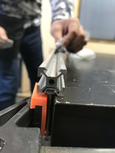
◆Rail for liner movement I made V-Slots in upper side and bottom of aluminum’s frame for V-wheels. (left side and right side to use for stepper motor’s belt)

The machine didn’t shave both edges equally. Then I shaved twice for single slot. The second shave did with the different side of the machine from the first shave.
After the shaving, the edges were coarse. I used fine sandpaper to make the edges smooth.

![]()

◆Stepper Motor
We used a stepper motor and a belt to move a fan table.


- Stepper motor - KH42KM2-802
- Unipolar
- Step angle: 1.8 (=200 steps/rev.)
- Shaft diameter: 5mm
- Voltage 12V, Current 0.4A, Winding resistance 30Ω
- Holding torque: 3.2 kgf·cm
I designed acrylic parts and laser cut to fix the motor to the frame.


◆Servo Motor
We used 5 Servo motors to stand wands up.


- Servo Motor ー Micro Servo MG955
- Operating voltage 3.3V-6V
- Stall torque: 1.8 kgf·cm
Servo Motor Pin Assignment - Organge code connect to Uno Analog pin (ex. A1 stands for Analog #1 pin)
- Port A1 Servo #5
- Port A2 Servo #4
- Port A3 Servo #1
- Port A4 Servo #3
- Port A5 Servo #2
Red and Brown codes connect bread board’s VCC and GND respectively.
◆Fan table and Opto interrupter
I have designed tables to put V-wheels and place a Fan. Actual “interrupter” was a piece of an orange color paper. Opto interrupers placed in front of each wands respectively and connected with rainbow cable. The PCBs were bridged differently by soldering.


◆Electric parts
We used Arduino UNO as microcontroller and motor driver - HiLetgo RepCap A4988. A Heatsink put on the motor driver chip. The digital pins of Arduino Uno used for the stepper motor control.


Originally we planned to have limiter switch to move the Fan table back to start position. However the motor drivers got troubles after several movement testing even though installing new one and no problem at the beginning. Then we gave up the auto returning. Although we tested 4 to 5 motor drivers, the results were the same. We just used a limit switch as starting the moves of the Fan table.
Used Limit switch was TOOHUI - T241
◆programming
Basically I started programming from each part of machine movement, such as motor moves clockwise - counterclockwise, the fan table stop at opto interrupter’s station as expected, and so on. Then combined each of them one by one. Arduino IDE has good examples for stepper, servo and sensor. I really enjoyed the benefits in this project.
When I added a program to existing one, sometimes we saw nothing happened although it worked before the addition.
We made good use of serial monitor by adding text in the program to find where errors exist by having echos during programing processes. Since there were lots of try and errors, it was very helpful for me. (removed from final program already)
Notes
I would like to write down some hangs I learned during the works here.
Shaving V slot in aluminum frame
For V wheel, I shaved V slot. V slot’s surfaces should be as smooth as possible. It wasn’t easy for me. I learned some hangs to use the router. I’d like to leave them here.
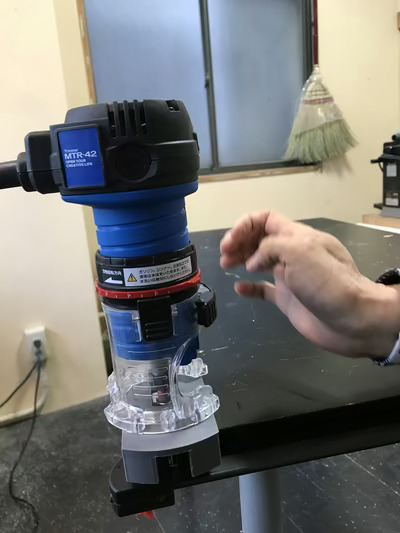
-
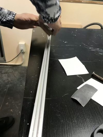
This is the machine I used. heavy drive unit in an upper part. Specially shaving from at the end of the frame, you need support the machine to place even against surface of the flame.
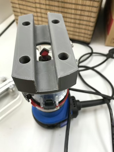
-
The machine has enough power to shave the frame. so you don’t need to put your weight on. Just support to move the machine evenly.
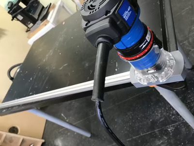
-
The bit has two sides. But it turns one direction. So one way go and return, not go backward. That means you try to shave a V slot in (a) round(s).
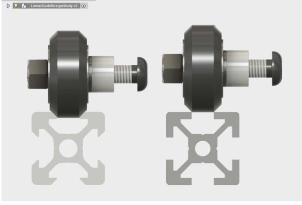
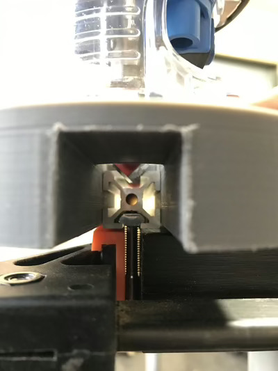
The Router
V-Groove Router bit and guide path. The bit has two side faces.
You should try to hold the machine even against the face of frame as much as possible.
The blade touchs to the frame like this.
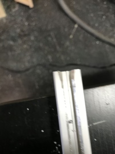
NG example made by me. The edge was shaved much.
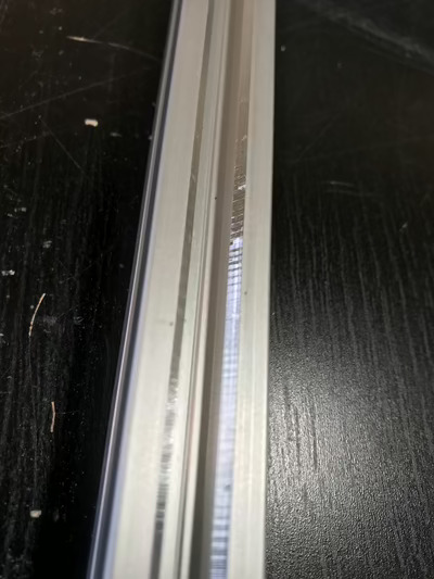
NG example made by me. I put some weight on the machine. Shaved faces are very rough..
Additional work to smooth out the faces. Used sand papers.
Finished.
Programming
As a very beginner, I used to believe that a good programing is written by scratch after mastered certain languages.
-
Even professional programmers refer to shared codes when they do programing.
-
We can find many examples shared online. However not all of them works as explained. If you don’t have the same results as you see there when you test it, don’t worry. You need check your cabling is correct, leave from the site and go next. Sometimes I spent quite a lot of time such programs.
-
That is bother, but we should visit Data Sheets of parts we use. It saved me when I encounterd some troubles.
Motor Driver
As we may see it in a data sheet, motor driver produces heat.
During the machine building work, even though we put a small heat sink on the motor driver, 4 motor driver units were broken, provably due to heats.
At the beginning, I didn’t think the motor driver had broken and believed programming errors. Then the programming work took time to finish.
Mobile Battery
No mobile battery was not broken during the machine building work. But I had 3 mobile battery broken which used in tests for final project and I decided to change from mobile battery to AA dry battery for my Final project robot.
I suppose that a reason of this is to leave mobile battery connected to cables on state.
So it would good to turn off soon when you leave from the tests.