Helmut Uwe [OOVAE] Terton - Fab Academy |
||
Helmut Uwe [OOVAE] Terton - Fab Academy |
||

Assignment tasks for Week 4:
Group assignment
Individual assignment
Contents
Due to our team members dispersed throughout the world and using different boards, I did benchmark my own boards:
ESP32-C3, ATTINY3216 and UNO R3 (ATmega328P).
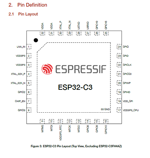
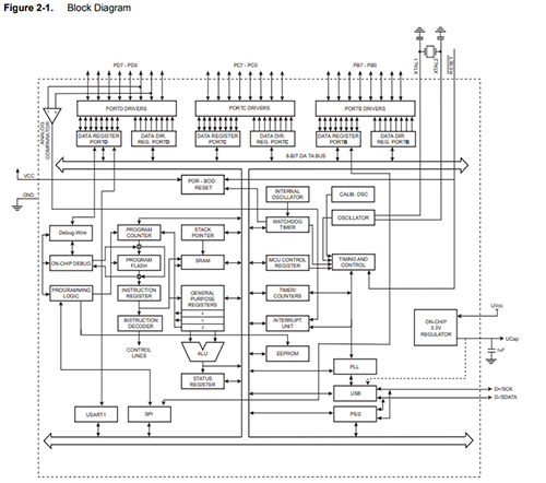
ESP32-C3
The information below was sourced from a datasheet provided by Espressif
https://www.espressif.com/sites/default/files/documentation/esp32-c3_datasheet_en.pdf
Overview
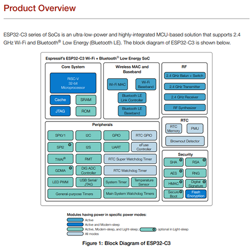
Features
WiFi
Note that when ESP32-C3 scans in Station mode, the SoftAP channel will change along with the Station channel o Antenna diversity o 802.11mc FTM
CPU and Memory
Bluetooth
Analog interfaces
Security
Timers:
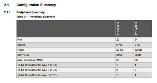
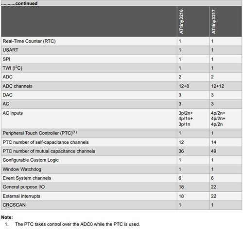
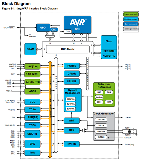
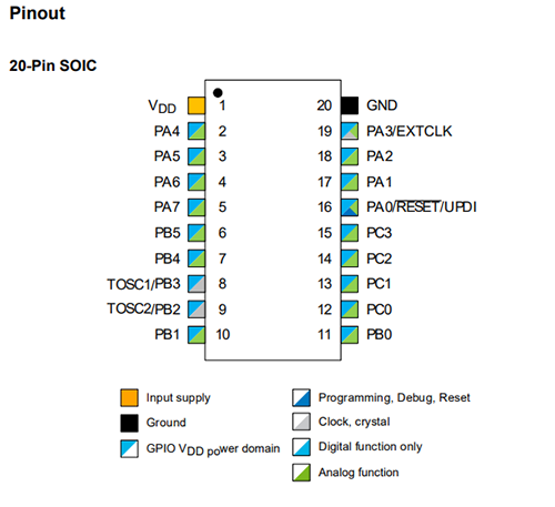
ATTINY3216
The information below was sourced from a datasheet provided by Microchip
https://ww1.microchip.com/downloads/en/DeviceDoc/ATtiny3216-17-DataSheet-DS40002205A.pdf
Overview
The ATtiny3216/3217 are members of the tinyAVR® 1-series of microcontrollers, using the AVR® processor with hardware multiplier, running at up to 20 MHz, with 32 KB Flash, 2 KB of SRAM, and 256 bytes of EEPROM in a 20- and 24-pin package. The tinyAVR® 1-series uses the latest technologies with a flexible, low-power architecture, including Event System, accurate analog features, and Core Independent Peripherals (CIPs). Capacitive touch interfaces with Driven Shield+ and Boost Mode technologies are supported with the integrated Peripheral Touch Controller (PTC).
Features
I/O Memory
All ATtiny3216/3217 I/Os and peripherals are located in the I/O memory space. The I/O address range from 0x00 to 0x3F can be accessed in a single cycle using IN and OUT instructions. The extended I/O memory space from 0x0040 to 0x0FFF can be accessed by the LD/LDS/LDD and ST/STS/STD instructions, transferring data between the 32 general purpose working registers and the I/O memory space. I/O registers within the address range 0x00-0x1F are directly bit-accessible using the SBI and CBI instructions. In these registers, the value of single bits can be checked by using the SBIS and SBIC instructions.
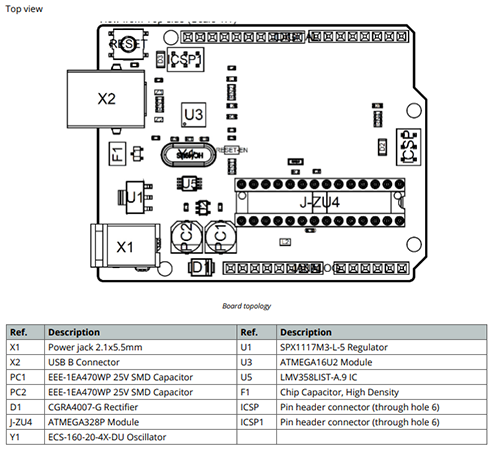
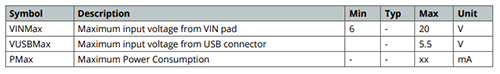
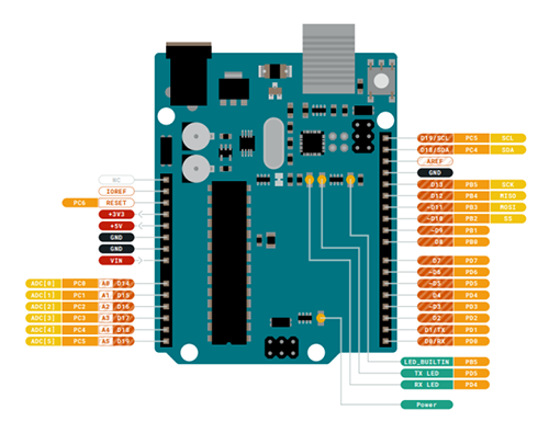
Arduino UNO R3
The information below was sourced from a datasheet provided by Arduino
https://docs.arduino.cc/resources/datasheets/A000066-datasheet.pdf
According the data sheet the Arduino UNO R3 is the perfect board to get familiar with electronics and coding. This versatile microcontroller is equipped with the well-known ATmega328P and the ATMega 16U2 Processor. This board will give you a great first experience within the world of Arduino.
Features ATMega328P Processor Memory AVR CPU at up to 16 MHz 32KB Flash 2KB SRAM 1KB EEPROM Security Power On Reset (POR) Brown Out Detection (BOD) Peripherals 2x 8-bit Timer/Counter with a dedicated period register and compare channels 1x 16-bit Timer/Counter with a dedicated period register, input capture and compare channels 1x USART with fractional baud rate generator and start-of-frame detection 1x controller/peripheral Serial Peripheral Interface (SPI) 1x Dual mode controller/peripheral I2C 1x Analog Comparator (AC) with a scalable reference input Watchdog Timer with separate on-chip oscillator Six PWM channels Interrupt and wake-up on pin change ATMega16U2 Processor 8-bit AVR® RISC-based microcontroller Memory 16 KB ISP Flash 512B EEPROM 512B SRAM debugWIRE interface for on-chip debugging and programming.
Power 2.7-5.5 volts.
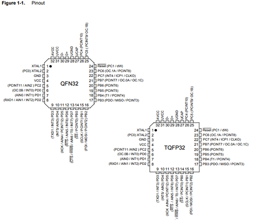
ATmega328P
The Arduino UNO R3 has an ATmega328P processor.
The information below was sourced from a datasheet provided by Microchip
https://ww1.microchip.com/downloads/en/DeviceDoc/Atmel-7810-Automotive-Microcontrollers-ATmega328P_Datasheet.pdf
Features
Special Microcontroller Features
Speed grade:
Comparison Table
ESP32-C3 |
ATTINY3216 |
UNO R3 (ATmega328P) |
|
Bluetooh |
Yes |
No |
No |
Wi-Fi |
Yes |
No |
No |
Processor |
32bit RISC V single core 160Mhz |
16-bit 20Mhz |
16 bit timer type A(TCA) 16 MHz |
Storage |
400 KB of SRAM (16 KB for cache) 384 KB of ROM |
2 KB of SRAM 256 bytes of EEPROM |
512/512/1024 Internal SRAM 512/512/1024 EEPROM |
Peripherals |
22 or 16 programmable |
Up to 14 self-capacitance channels |
22 Programmable |
Timers |
2 — 54-bit general-purpose timers 3 — digital watchdog timers 1 — analog watchdog timer 1 — 52-bit system timer |
1 x 16 bit timer type A (TCA) 2 x 16 bit timer type B (TCB) 1 x 16 bit timer type D (TCD) |
One 8-bit Timer/Counters with Separate Prescaler and Compare Mode (two 8-bit PWM channels) One 16-bit Timer/Counter with Separate Prescaler, Compare and Capture Mode (three 8-bit PWM channels |
Operating Voltages |
3.0 V - 3.6 V |
1.8V - 5.5V |
2.7 - 5.5V |
Links to Dorian and Lisa's embedded programming pages where they have compared their boards and micro processors:
Dorian Somers: https://fabacademy.org/2023/labs/kamplintfort/students/dorian-somers/weekly-assignments/week04
Lisa Schilling: https://fabacademy.org/2022/labs/kamplintfort/students/lisa-schilling/week08.html
Individual assignment:
Part 1: Install Arduino IDE, Install the ESP32-C3 board and program the ESP32-C3 board.
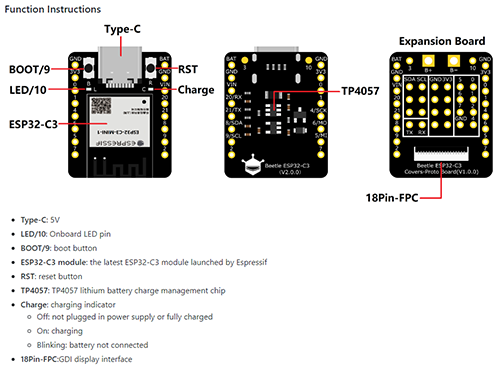
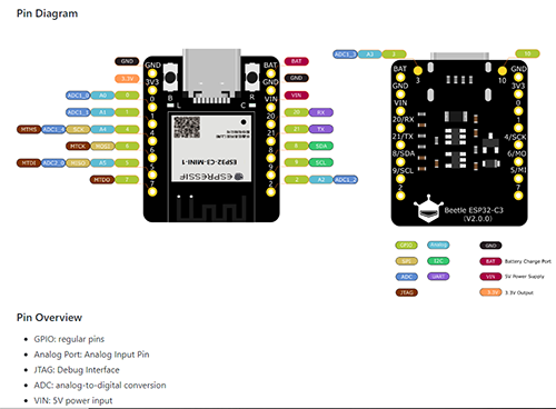
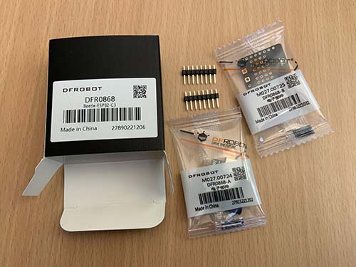
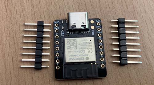
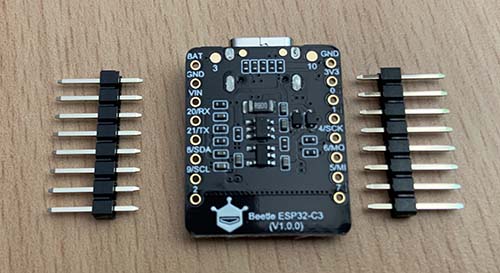
Here are a few pictures of the unboxing of the ESP32-C3 Beetle board (very exciting):
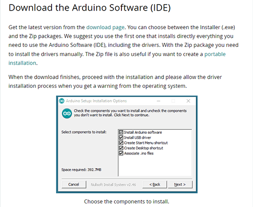
I had to download Arduino for Windows from the Arduino website:
https://docs.arduino.cc/software/ide-v1/tutorials/Windows
and installed all the IDE plus drivers for Arduino
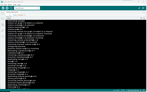
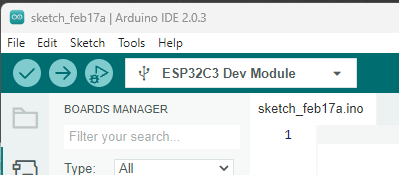
How to install the ESP32-C3?
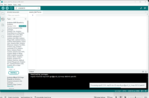
When plugged into the laptop the Arduino GUI is recommending a LOLIN S3 board.
I followed the following instructions provided by
https://wiki.dfrobot.com/SKU_DFR0868_Beetle_ESP32_C3
in order to install the board.

After selecting the Board under Tools, I went back to tools and selected USB CDC On Boot: Enabled.
This will allow me to print on the Arduino monitor via USB, afterward I made sure that the correct USB port has been selected, in my case it is port 4.
Next step was to insert the following code and burn it to the processor.
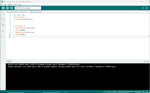
This code makes the inbuilt blue LED blink every 1000 millisecond.
Ahmed taught us the basics of programming and from what I had learned I wrote a function myBlink(); // function myBlink executing the code below
That is executing the following code that makes the blue LED blink at with a delay of 1000.
The higher the number the slower it will blink, the smaller the number the faster the LED will blink
void myBlink() {
  digitalWrite(ledPin, HIGH);  // turn the LED on (HIGH is the voltage level)
  Serial.println("on");
  delay(1000);                      // wait for a second
  digitalWrite(ledPin, LOW);   // turn the LED off by making the voltage LOW
  Serial.println("off");
  delay(1000);                      // wait for a second
}
The code also writes ON and OFF in the Arduino GUI serial monitor
Delay 1000
Delay 25
Delay 2500
I looked up some Python Code from https://roboindia.com/tutorials/python-with-arduino/
To see the differences between the two languages but had no time to go into more detail.
import serial #for Serial communication
import time   #for delay functions

arduino = serial.Serial('com5',9600) #Create Serial port object called arduinoSerialData
time.sleep(2) #wait for 2 secounds for the communication to get established

print arduino.readline() #read the serial data and print it as line
print ("Enter 1 to get LED ON & 0 to get OFF")


while 1:      #Do this in loop

    var = raw_input() #get input from user


    if (var == '1'): #if the value is 1
        arduino.write('1') #send 1
        print ("LED turned ON")
        time.sleep(1)

    if (var == '0'): #if the value is 0
        arduino.write('0') #send 0
        print ("LED turned OFF")
        time.sleep(1)
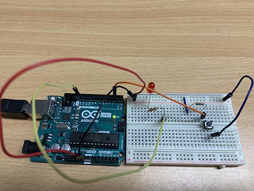
The next experiment was to use an Arduino UNO R3 to add a LED plus button and control the interactions via C code. Ahmed has taught us some of the code used in this example in our tutorial on the topic of Embedded Programming.
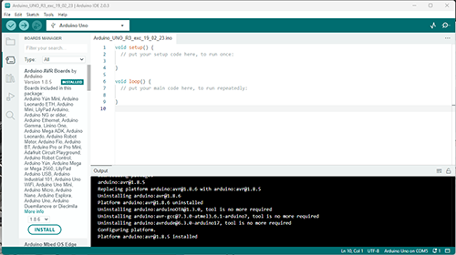
First I needed to install the Arduino UNO R3
Once the board and its drivers were installed successfully, I went to the Tinkercad website to design the circuit set-up.
According to Wikipedia (2023), Tinkercad (https://www.tinkercad.com/dashboard) is a free-of-charge, online 3D modeling program that runs in a web browser. Since it became available in 2011 it has become a popular platform for creating models for 3D printing as well as an entry-level introduction to constructive solid geometry in schools.
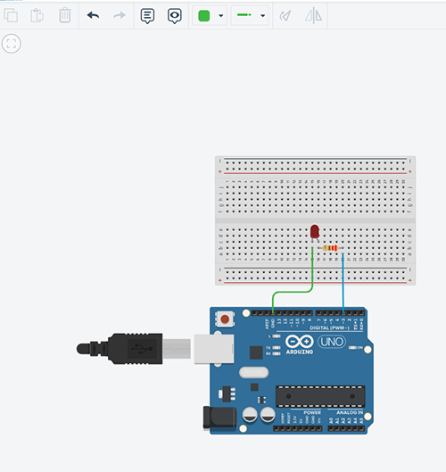
The first design was to make a diode blink. The following Figure shows how the circuit is designed using a 220 Ohm resistor and a LED light, both installed on a breadboard. All parts came with the Arduino starter kit.
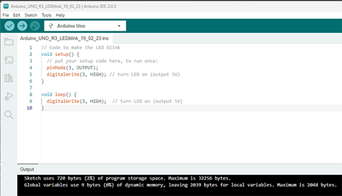
Here is the code that connects the Arduino UNO with the breadboard and components and makes the LED blink
Next step up from here was to add a button that allows for turning on and off the LED light.
I looked up a tutorial on the Arduino tutorial website http://www.arduino.cc/en/Tutorial/Button
The tutorial was very helpful. The comments in the code explain nicely what every line of code is doing and why.
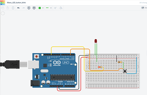
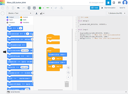
Also, Tinkercad is providing code for the circuit layout and a simulation mode that can test if the set-up is working or not.
My final experiment was to do something with the Fibonacci sequence. I thought this would tie in nicely with the theme of my final project.
So, for this exercise I wanted to write some code that makes the LED come on for 1,2, 3, 5, 8, 13, 21 ……..seconds each time the button is pressed.
I did a google search which returned a few code examples, I used the one from Patrick Devivo (https://gist.github.com/patrickdevivo/1604221) and combined it with the existing button press code. The final code is below.
/* this code will make the LED light up for a certain duration based on the Fibonacci sequence
1 = one second
2 = two secondes
3 = three seconds
5 = five seconds
etc
*/


int ledPin = 13;             // the pin that powers the LED
const int buttonPin = 2;     // the number of the pushbutton pin
int i = 0;                   // declares the variable i with a value of zero
int buttonState = 0;         // variable for reading the pushbutton status

int fib(int initial) {      // set integer for Fibonacci sequence
  if (initial <=1) {
    return initial;
  }
  else {
    return fib(initial-1)+fib(initial-2);
  }
}

void setup() {
  Serial.begin(9600);
  pinMode(ledPin, OUTPUT);
}

void loop() {
  // read the state of the pushbutton value:
  buttonState = digitalRead(buttonPin);

  // check if the pushbutton is pressed. If it is, the buttonState is HIGH:
  if (buttonState == HIGH) {
    // turn LED on:
    digitalWrite(ledPin, HIGH);
    delay(fib(i)*1000); // calculate fibonacci number and set duration of LED on
    i++;
  } else {
    // turn LED off:
    digitalWrite(ledPin, LOW);
    delay(1000);

     }

}
Summary
This week I have investigated datasheets for three different microprocessors/boards. I learned what some of the specs mean in regards of speed, memory, operating voltages and peripherals.
I got familiar with some colour codes of pin-outs and how to read them which is important in regards of programming and also what kind of input and output devices can be used and linked to the boards.
From the three boards I tested the ESP32-C3 seems to be the more superior board in regards of speed, memory storage and it has also Bluetooth and wi-fi capabilities. The ATtiny is the weakest.
The second part of this week's assignment was learning how to set up the boards via the Arduino IDE, alter and create some code written in C and plan, design a circuit in Tinkercad and put it all together with electronic components using a bread board. Ahmed provided us with a great revision on programming basics that I could apply to figuring out how to write a simple code making a LED light come on for a certain duration based on the Fibonacci sequence. The part I enjoyed the most was designing the circuit boards in Tinkercad, it is very intuitive and has a fantastic simulation function and spits out code in blocks and in C.
Files
LED blink circuit layout in Tinkercad
https://www.tinkercad.com/things/1QxLgEq7sUs
LED blink plus button circuit layout in Tinkercad
https://www.tinkercad.com/things/jRadKcc0wRL