Helmut Uwe [OOVAE] Terton - Fab Academy |
||
Helmut Uwe [OOVAE] Terton - Fab Academy |
||

Assignment tasks for Week 8:
Group assignment
Contents
Last year (2023) I collaborated with Dorian and Lisa, their documentation in regards of the in-house PCB production can be accessed via below links:
Dorian Somers
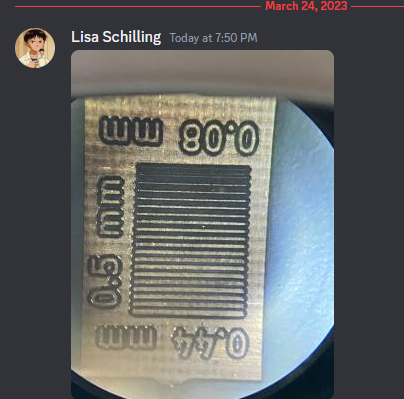
Lisa Schilling
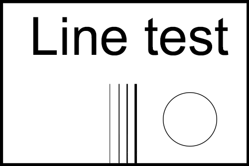
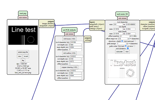
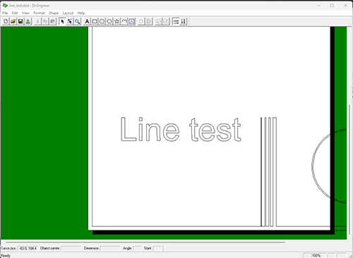
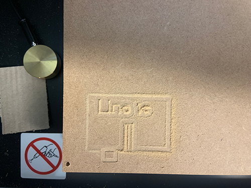
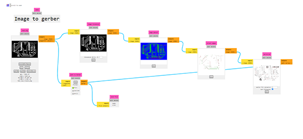
The following line test graphic had been designed in Adobe Illustrator in vector format and then saved as in PNG format.
This format can be used with the MODS online tool.
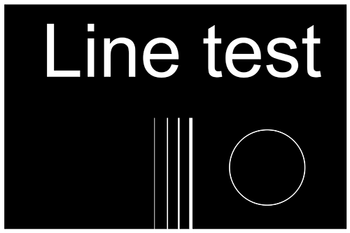
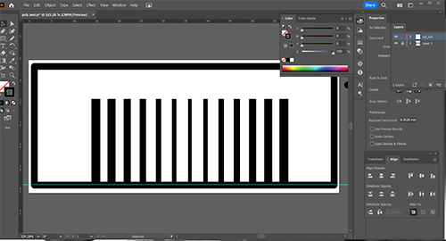
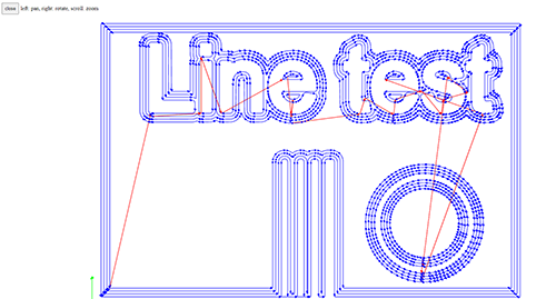
The MODS tool allows for Gerber code creation based on bitmap image formats. The images have to be in black and white inverted.
MODS: https://pub.fabcloud.io/project/mods/
We leaned to use MODS in our weekly tutorial from Ahmed.
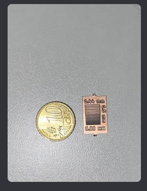
Below is are e few different image files used for line testing. Line testing is the process of testing different settings of the CNC router and several tools.


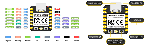
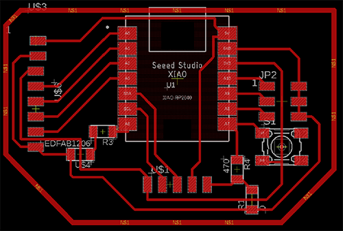
In our weekly tutorial we used KiCad to design a development board that is the host to a Seeeduino XIA ESP32-C or samd21.
I have decided to buy a samd21 processor, the only one available in Australia at the time.
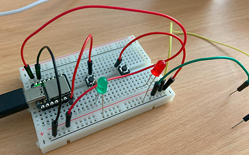
To determine the circuit board layout I wanted to make a prototype using a breadboard, conventional old style resistors, LED and button.
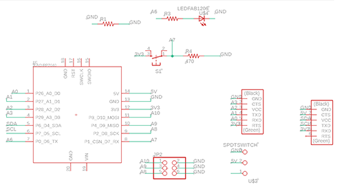
This did allow me to visualise the set-up which I then could transfer to the KiCad software and design the layout for the PCB to be routed.
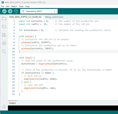
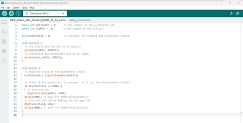
I googled some Arduino code to be used for the breadboard prototype, see Figure 17.
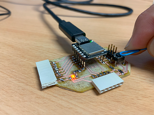
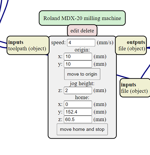
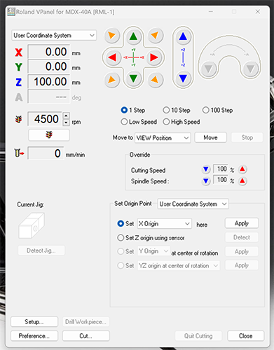
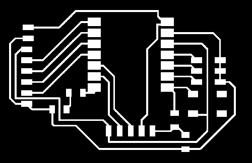
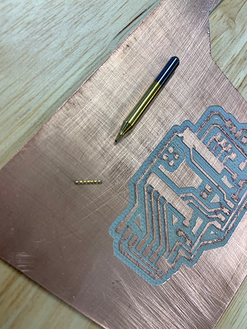
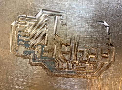
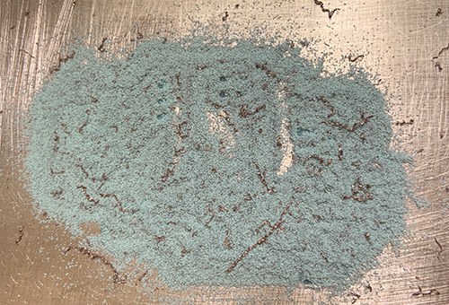
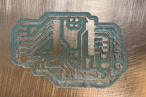
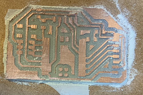
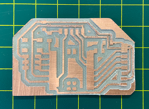
Similar to the line test work pipeline, black and white inverted images were created to be used in MODS to create G-Code (Gerber-Code). The code was loaded via the VPanel app to the Roland MDX-40A router to route the traces and to eventually cut out the board from the copper plated plastic board (Single laminated copper clad, 15cm x 15cm, 1.5mm thickness.
It needed a few attempts to get it all right, I experienced broken off tools, uneven router bed, double sided tape that came off to name a few.
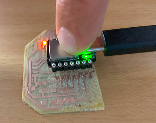
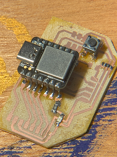
The following components needed to be soldered onto the PCB:
  const int buttonPin = 6;     // the number of the pushbutton pin
const int ledPin =  13;      // the number of the LED pin

int buttonState = 0;         // variable for reading the pushbutton status

void setup() {
  // initialize the LED pin as an output:
  pinMode(ledPin, OUTPUT);
  // initialize the pushbutton pin as an input:
  pinMode(buttonPin, INPUT);
}

void loop() {
  // read the state of the pushbutton value:
  buttonState = digitalRead(buttonPin);

  // check if the pushbutton is pressed. If it is, the buttonState is HIGH:
  if (buttonState == HIGH) {
    // turn LED on:
    digitalWrite(ledPin, HIGH);
  } else {
    // turn LED off:
    digitalWrite(ledPin, LOW);
  }
}


    //Pressing a button that will light up a LED and make it blink

const int buttonPin = 7;     // the number of the pushbutton pin
const int ledPin =  6;      // the number of the LED pin

int buttonState = 0;         // variable for reading the pushbutton status

void setup() {
  // initialize the LED pin as an output:
  pinMode(ledPin, OUTPUT);
  // initialize the pushbutton pin as an input:
  pinMode(buttonPin, INPUT);
}

void loop() {
  // read the state of the pushbutton value:
  buttonState = digitalRead(buttonPin);

  // check if the pushbutton is pressed. If it is, the buttonState is HIGH:
  if (buttonState == HIGH) {
    // turn LED on:
    digitalWrite(ledPin, HIGH);
  delay(1000); // Wait for 1000 millisecond(s)
  // turn the LED off by making the voltage LOW
  digitalWrite(6, LOW);
  delay(1000); // Wait for 1000 millisecond(s)
}
}