Helmut Uwe [OOVAE] Terton - Fab Academy |
||
Helmut Uwe [OOVAE] Terton - Fab Academy |
||

Assignment tasks for Week 7:
Group assignment
Contents
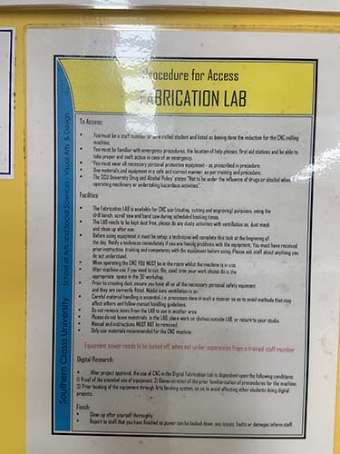
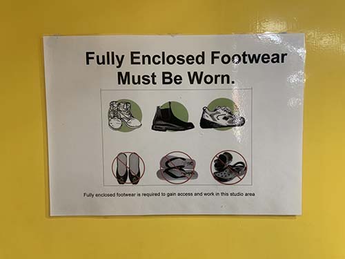
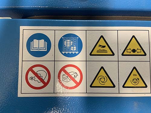
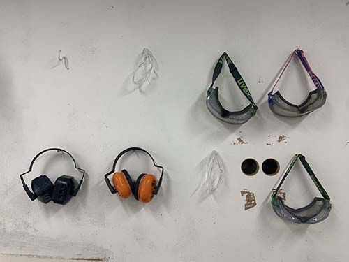
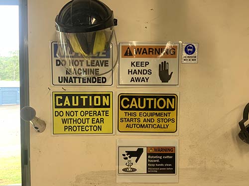
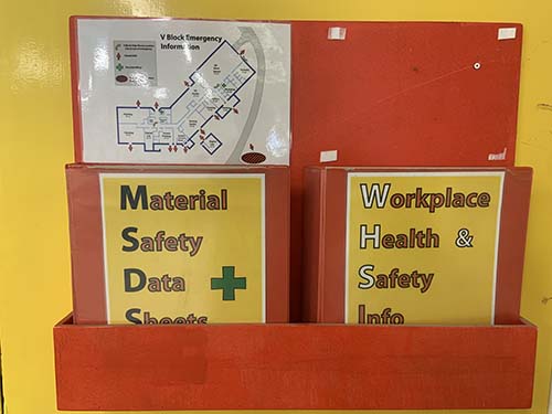
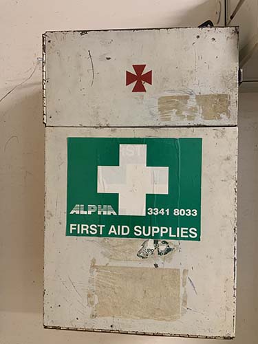
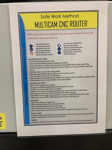
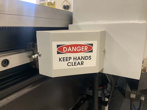
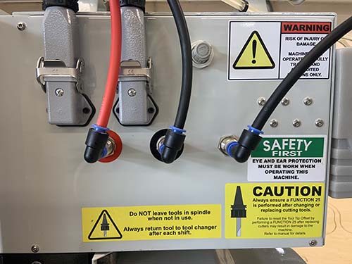
The following images illustrate the Work Health and Safety (WHS) procedures and warnings.
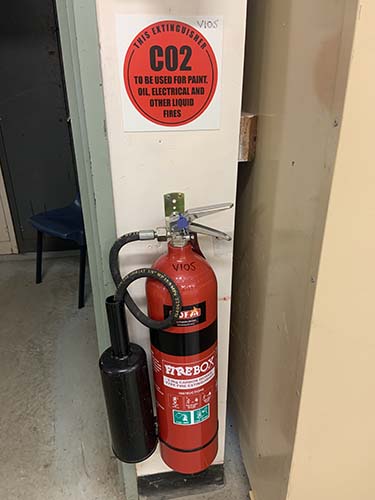
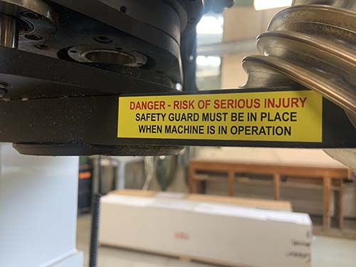
Working in university environment means that a lot of procedures had to be written and staff and students need to be inducted into spaces where there could be potential harm such as the CNC router room.
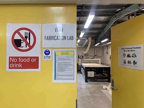
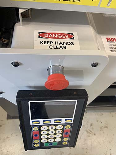
Before the room can be entered the following warning signs and procedures should be read and followed.
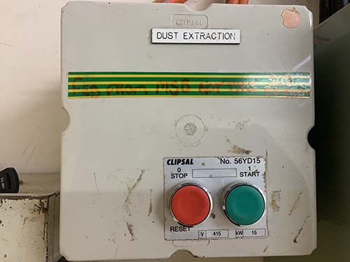
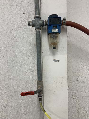
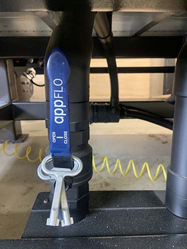
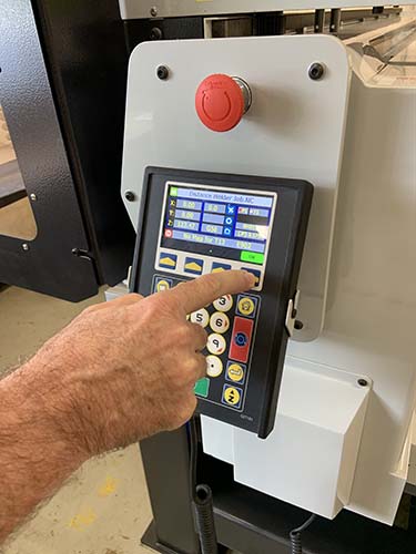
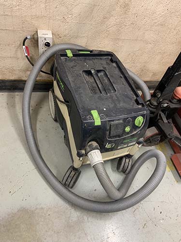
The following is a run down on all the steps that are involved in safe operating the Multicam SR2412Vi CNC router. https://multicam.com.au The air compressor needs to be switched on and correct pressure settings to be checked. The air compressor is in a separate room that is ventilated and lit.
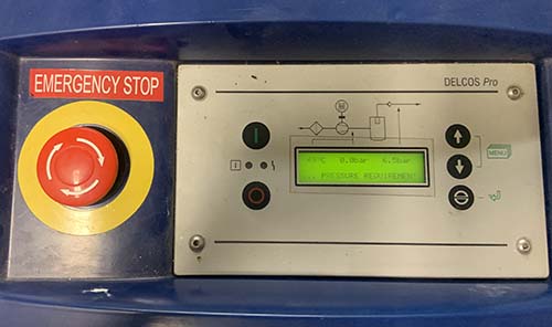
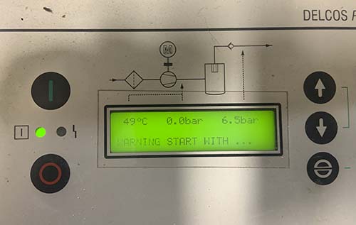
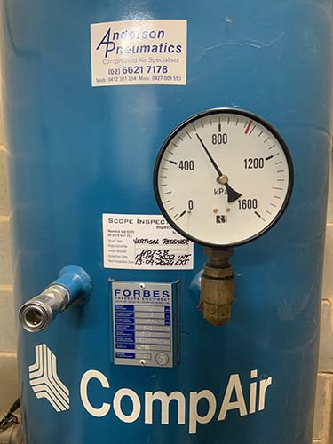
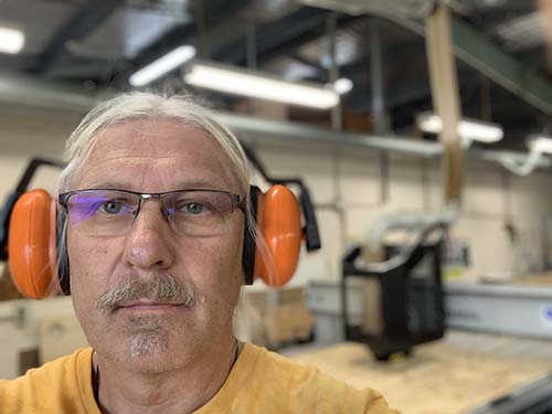
After the air compressor has been checekd, turned on and assured that the correct pressure of 6.5 bar has been achieved I wen back to the cnc-router room to check the personal safety equipment again.
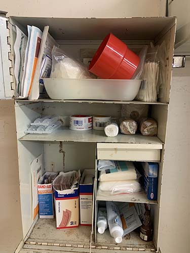
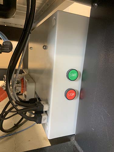
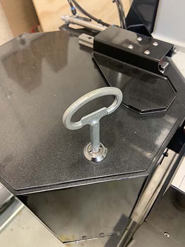
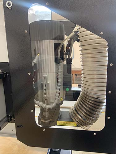
Several steps are involved before the cnc-router can be safely operated:
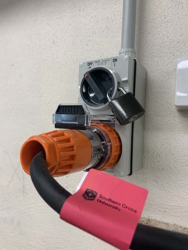
Before the router is finally turned on the pressure air is turned on and the machine is cleaned from dust and debris and it is made sure that there are no objects sitting against or on top of the machine and everything is freely accessible.
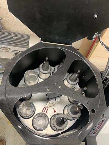
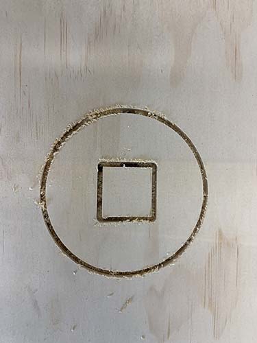
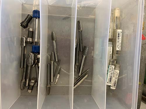
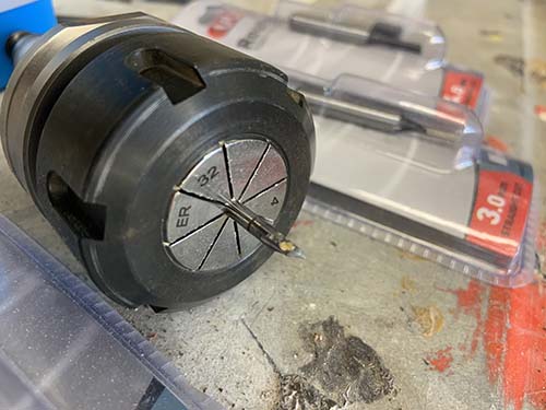
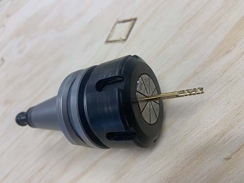
The next part will cover a test runout, alignment, fixturings, speeds, feeds, materials, and toolpaths for the Multicam router.
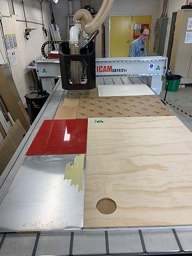
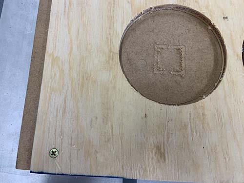
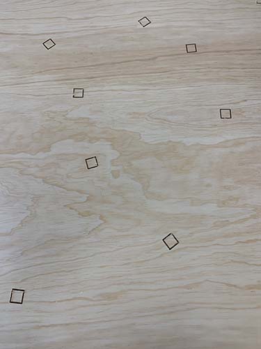
To prevent the plywood from lifting up it has been screwed down to the waste-board.
The vacuum wasn't strong enough to hold down the plywood sheet.
Care needs to be taken that the router tool does not run into the metal screw.
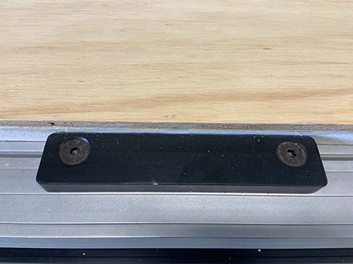
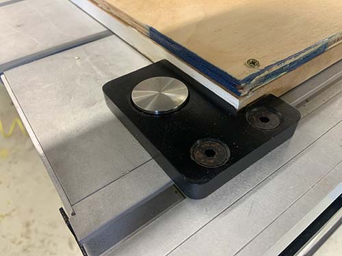
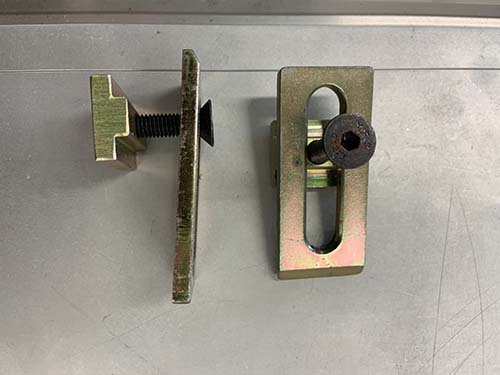
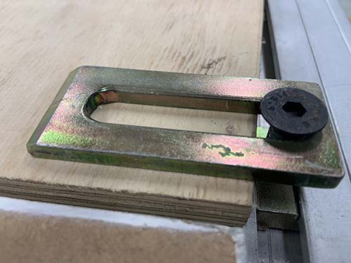
There also other means of fixating material to the work bench such as clamps and metal bars for alignment.
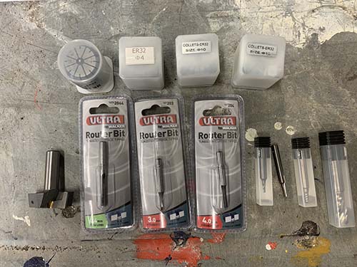
I found a website that has all information about speeds, feeds, materials, and toolpaths and can be obtained from the following website: https://cncrouterbits.com.au/technical_speeds_feeds
make (design+mill+assemble) something big (~meter-scale)
extra credit: don't use fasteners or glue
extra credit: include curved surfaces
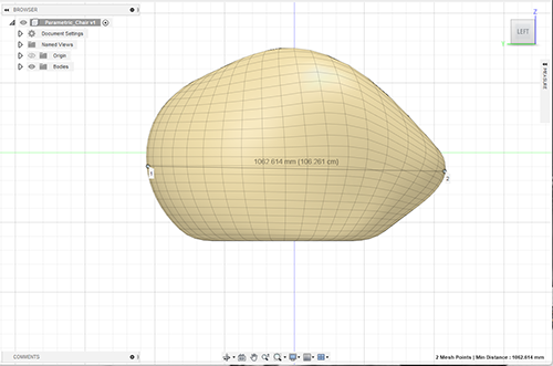
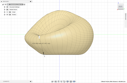
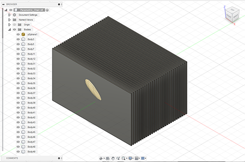
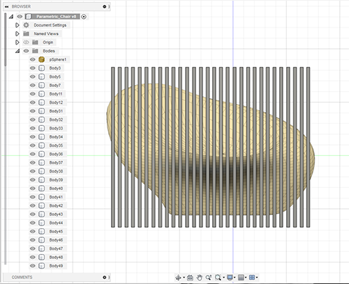
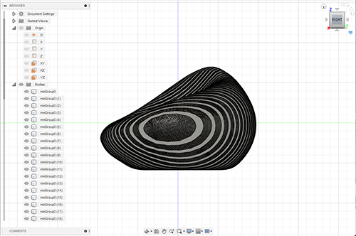
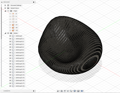
For the individual assignement I had planned to design a parametric organic shaped chair for assembly.
I used 9mm plywood. The plywood I could source was of lowest grade because we have a building material shortage at the momemnt in Australia.
The production pipeline consists of the folloing stages:
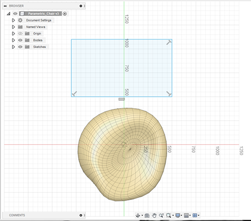
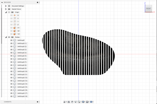
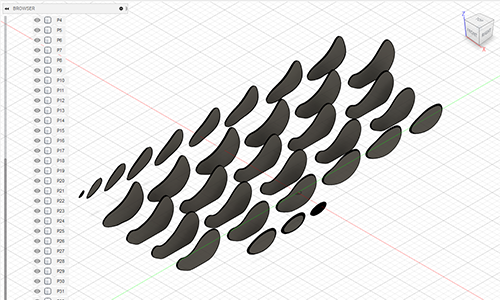
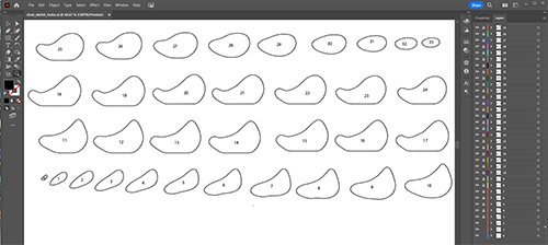
The individual panles of the chair had been distributed out to one layer and be saved as SVG file ready to be imported into Adobe Illustrator. I had to do this because Enroute which creates the G-Code for the cnc-router only can import EPS files. That was my knwoledge at the time. Later I found out how to use FreeCad as a bridging tool to create an EPS file for Enroute.

The below videos show the router in action cutting out the parts for the chair.
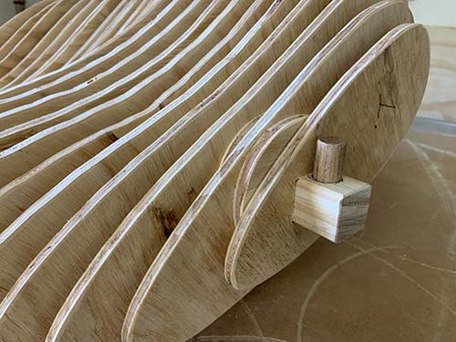
Once the parts had been routed they got sanded and filed to fit the centre square bar.
The next pictures illustrate the assembly process.
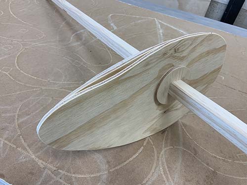
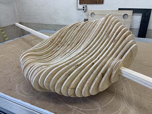
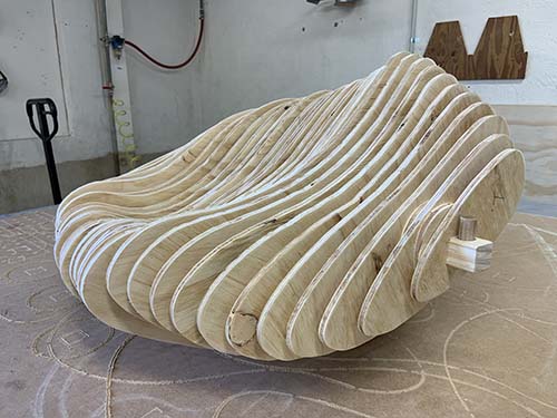
The chair is complete, it is planned to make a pillow that fits into the chair to make it more comfortable. The chair is 1050 mm in length and all parts are timber.
Summary
I really enjoyed this assignment because I like working with wood. This assignment allowed me to create an organic shape in Fusion360 which I haven't done before. The idea was to use the Boolean function to slice the object so that a resulting SVG file could be used.
Unfortunately the software version of Nroute that is generating the G-Code for the router did not allow for SVG import. This was the reason why I had to run the SVG file coming from Fusion360 through Illustrator in order to create an EPS file which could be used in Nroute.
After having completed the cutting of the chair pieces I set down and investigated ways to export files from Fusion 360 and use Inkscape to convert them into Enroute.
Instead of one week this project took me four weeks. I spent one week learning software and designing the chair, one week to get to know the Multicam SR2412Vi CNC-router.
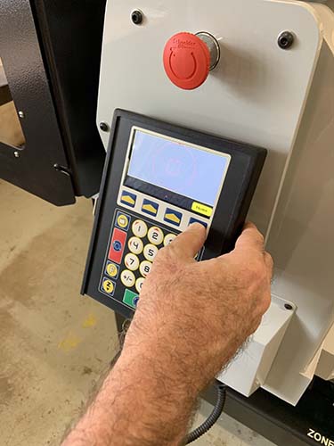
The router has no memory, every setting needs to be set again once the machine had been turned off.
At the end everything worked out as planned and I am now more confident to use the cnc-router thanks to this assignment activity.
Files
1st set of Chair Panels EPS file
2nd set of Chair Panels EPS file
Organic Chair design in Fusion360
Organic Chair design, individual panels, in Fusion360