Helmut Uwe [OOVAE] Terton - Fab Academy |
||
Helmut Uwe [OOVAE] Terton - Fab Academy |
||

Assignment tasks for Week 3:
Group assignment:
characterise your lasercutter's focus, power, speed, rate, kerf, joint clearance and types
Individual assignment:
Learning outcomes
Contents
The goal was to design something that can be produced via a vinyl cutter.
Vinyl cutters can only process vector graphics. According to Adobe, Vector artwork is built from vector graphics, which are images created with mathematical formulas.
A good software to create vector graphics is Inkscape , Illustrator or Corel Draw.
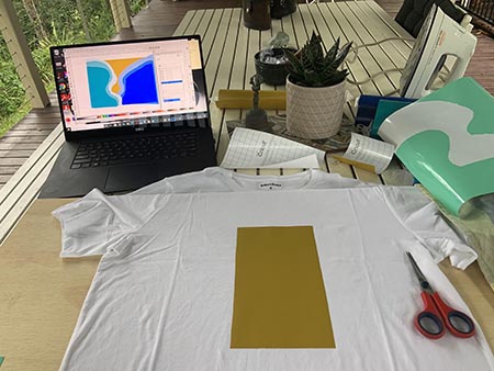
I used Inkscape to draw up a piece of art for my vinyl cutter experiment. It is not finished yet.
The previous week I got a drawing tablet and I thought that in order to practice the tablet and stylus pen I would use it for this assignment.
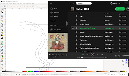
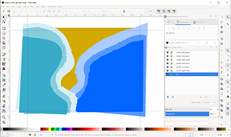
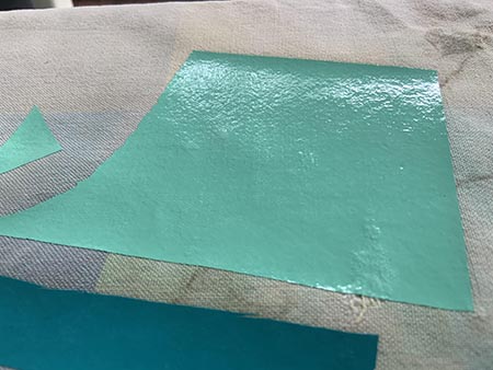
As mentioned I have some tremor in my right hand (I am right handed). While trying to draw a curve it came out all wavy. While drawing I was listening to Meeting of Two Oceans by Chinmaya Dunster (figure 1). Inspire by the title and music I came up with the artwork seen in figure 2 to 5. It is a top down few of the Indian Ocean meeting the Atlantic Ocean in South Africa.
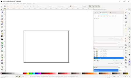
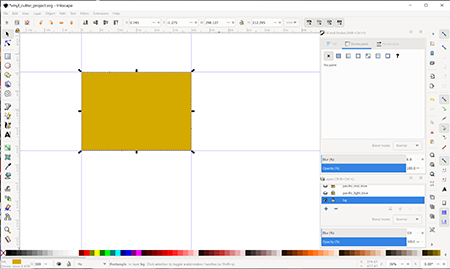

Working Inkscape file: vinyl_cutter_project.svg (56 KB)
It seems that part of my course is hunting down equipment that I need. So this time it was the vinyl cutter. Luckily one of the campuses at Caboolture, only 100 kms from here, has a Roland GX 24 vinyl printer that I could borrow.
I picked it up and moved it to my home. I left it rather late to get it going. It came with a software disc but I have no disc drive. It took me three hours to find the software on the internet. Roland's software support is rather poor.
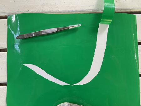
Anyways, finally I got it tow work and was able to do a test run on one of the layers I have designed for the oceans as depicted in figure 8. The wavy curve came out nicely.


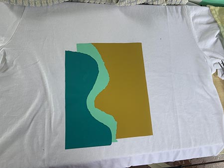
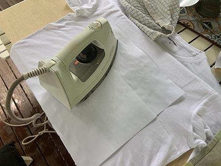
Inspired by my co-students that ironed their vinyl design onto t-shirts I tried myself. Got a t-shirt and stuck on all the cut-outs according to the original artwork designed in Inkscape.
I did an iron on test on a tea-towel which went fine.
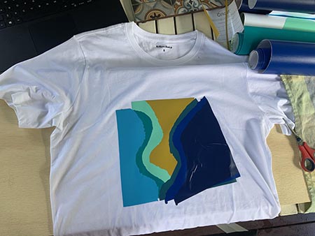
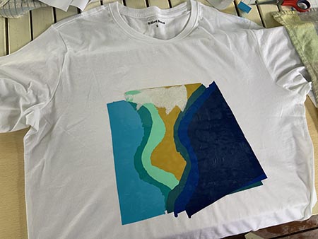
Applying the cuts was kind of tricky and the last one got all wrinkly. I wasn't able to peel it off again.
After applying heat with the iron onto the vinyl I had great difficulties peeling off the protective paper sheets. You can see in figure 29 that their is paper stuck to the vinyl. I peeled it all off and now have a blank white t-shirt that I might use for other experimentations.
This week's assignment consists of two parts. Number 1 is a group assignment and number 2 is an individual project where we have to use a vinyl cutter to cut and make something and secondly design and make a parametric construction kit using a laser cutter.
Part1: characterise your lasercutter's focus, power, speed, rate, kerf, joint clearance and types.
I drew a simple square in Adobe Illustrator with a stroke line of 0.025mm width as per the specs of the Epilog 24 Helix Laser cutter.
This width is used for vector line cutting only, everything thicker will be seen as an engraving job by the Epilog Job Manager software.
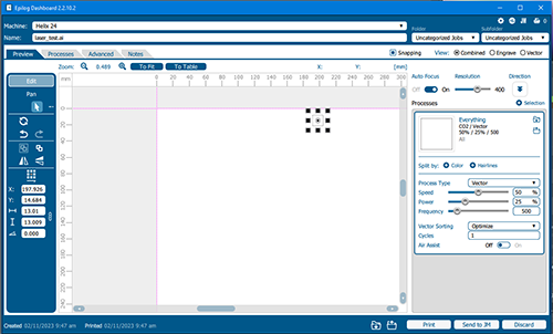
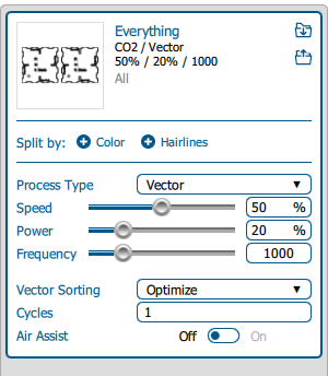
The Epilog Job Manager helps managing the jobs before they are sent to the laser cutter. Focus, power, speed and frequency are some of the settings that can be controlled via the manager amongst other settings for engraving, auto-focus, resolution and air assist.
Although this is a group task, I did it by myself because all our group members are studying and working remotely. Dorian is in France and Lisa in Germany.
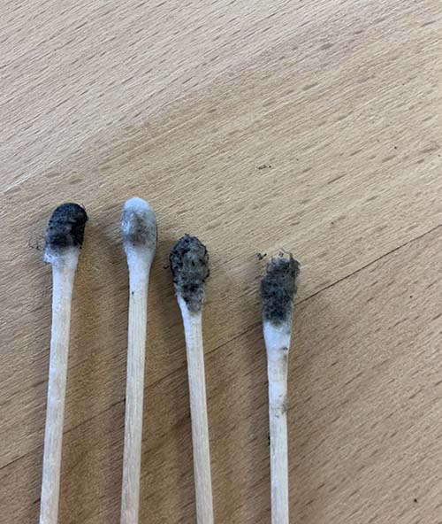
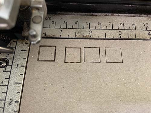
First, I started playing with the manual focus settings. As can be seen in the illustration the further the laser head is away from the medium to be cut the more blurry and wider the cut becomes. The distance had been manually adjusted till a near perfect cut was achieved (Figure 16 - the fourth on the right). Learning about the manual focus settings was very helpful for me because I plan to laser cut and engrave uneven surfaces in the future.

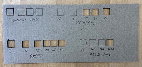
Next, I played with the power settings and changed them by 5% increments from 5% to 25%. It became obvious that with lower power the laser wasn't able to cut through the material and only penetrate the surface. The higher the settings the wider the kerf.
This experience taught me to look for the sweet spot where the power is high enough to cut through and create a very fine kerf.
Playing with the speed settings was the most interesting test because I nearly set my cardboard on fire. 5% speed created a very unsatisfactory wide cut with the edges on fire. The faster the speed the more accurate the cuts became.
When experimenting with the frequency settings I decided to apply four settings, 10, 50, 100 and 5000.
At the lowest setting the laser created a dotted penetration that was clearly visible. With 50 it became more like a line but individual dots can be still seen. At 100 the laser produced a continuous line. The 5000 setting created a clear cut through the material with a nice sharp cutting line.
On the lab's computer that is used for design and set-up, I found a template for kerf and hinge testing, which I used for a test (Figure 20). I set used optimal settings for 2mm cardboard cutting.

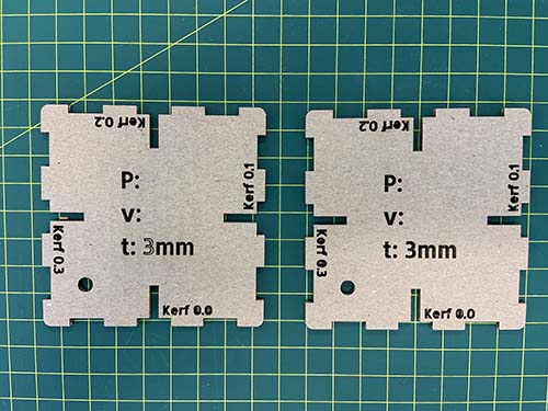
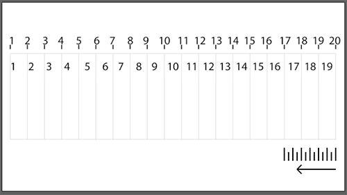
Further I came across a kerf line test that makes lots of sense to me, it uses two lines of testing and therefore different kerf distances can be compared to each other.
Summary
This exercise was most useful because I became familiar with the laser cutter and it's different settings and feel more comfortable using the devise.
Laser Cutting - Individual Assignment
The parameters of this assignment was to:
Design, lasercut, and document a parametric construction kit and account for the lasercutter kerf.
The construction kit should allow the user to assemble the parts in multiple ways, and possibly make something 3D with it.
I decided to connect all my assignment items to my major project wherever possible. So, this week's laser cutting assignment is informed by Fibonacci sequences and numbers just like the final project is.
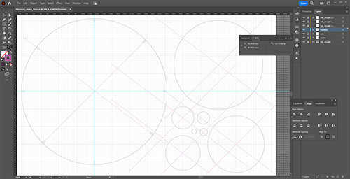
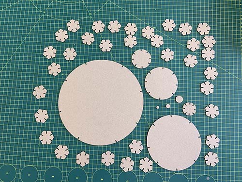
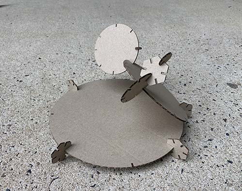
I designed a range of circles based on the sequence of 1,2, 3, 5, 8, and 21. Each number represents the diameter of a circle. The idea is to create pentagon shaped connectors that allow for multiple ways of assembly. The user can use the connectors and circles to build a three-dimensional mini sculpture.
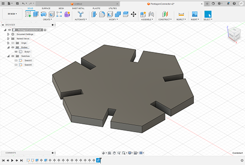
I did design the pentagon shaped connector in Fusion 360 in order to use more techniques and take advantage of the constraints available in Fusion 360.
I thought that it would be most likely that the kerf will impact of the widths of the slots and I would have to come back to the software for adjustments.
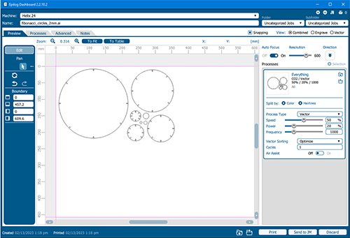
The material I was using for cutting is 2mm cardboard, after some tests I ended up with a width of 1.9mm. The slots hold perfectly together without pieces dropping or sliding out when assembled.
The following figures illustrate the design process in Fusion 360.
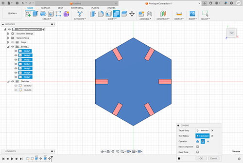
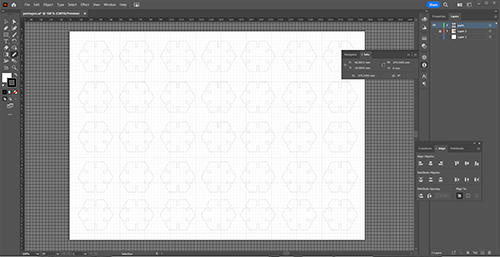
Fusion 360 is new to me, and I am a novice user it takes quite a long time to create shapes. This is why I decided to design the other parts of the parametric construction kit in Adobe Illustrator. From testing I knew that the slots had to be 1.9mm in with and I would not have to go back and change them.
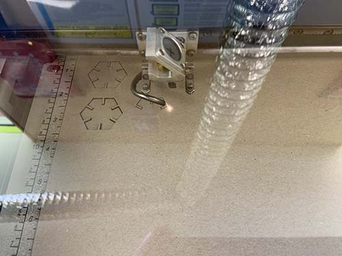
The following figure show the design, cutting and assembly process for the mini sculpture consisting of circle shapes and pentagon connectors.
Just out of curiosity I thought it would be nice to apply the Fibonacci measurements to triangles and squares.
I finished the layout for a triangular assembly, cut them and below is the final assembly.


In summary
I learned that with laser cutting a lot of testing has to be one before a sufficient result can be achieved. Going forwards between design software and laser cutter is important. To safe time and material it is best to make lots of prototypes on scrap material before committing to the final material and cut. Another important lesson was to avoid flames and smoke, otherwise the mirror needs cleaning and possibly gets damaged. The replacement mirrors are very expensive and a failed mirror can cripple the operations for weeks or months.