
This work is licensed under a Creative Commons Attribution-NonCommercial-ShareAlike 4.0 International License
Week 12: Molding and Casting
Apr 16, 2021Summary
This week's assignments
- Group assignment:
- Review the safety data sheets for each of your molding and casting materials ✔
- Make and compare test casts with each of them ✔
- Individual assignment:
- Design a 3D mold around the stock and tooling that you'll be using, mill it (rough cut + (at least) three-axis finish cut), and use it to cast parts:
- Document how you designed your 3D mould and created your rough and finish toolpaths for machining, including machine settings ✔
- Show how you made your mould and cast the parts ✔
- Describe problems and how you fixed them ✔
- Include your design files and ‘hero shot’ of the mould and the final object ✔
Resources Used
- Software: SOLIDWORKS, MODELA Player 4, VPanel for SRM-20
- Hardware: Roland SRM-20
Skills Gained
- Postive and Negative Mold Design, Mold Milling, Silicone Casting
My Weekly Schedule
Group Assignment
Apr 15, 2021During the Thursday review session, Greg showed us how to make a silicone mold. Due to time constraints, we decided to use a prepared wax block to get the silicone mold.
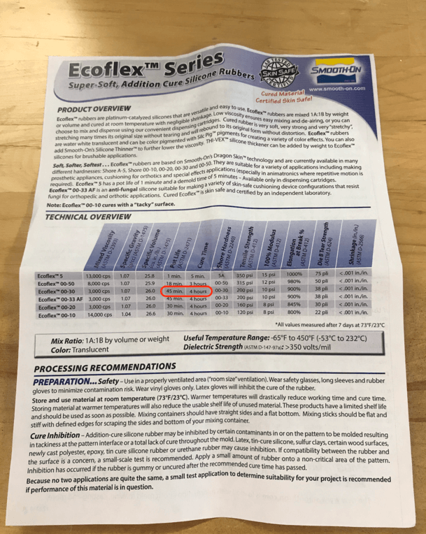
The products that we were going to use are all from the Smooth-On brand, and the one that we used for the group assignment was the Ecoflex 30. It is very important to read the datasheet first, specifically, we must pay attention to the following information when making a mold:
- Specific Gravity: 1.07g/cc
- Pot Life: 45 minutes
- Cure Time: 4 hours
- Mix Ratio By Volume: 1A:1B
- Mix Ratio By Weight: 1A:1B
- Color: Translucent
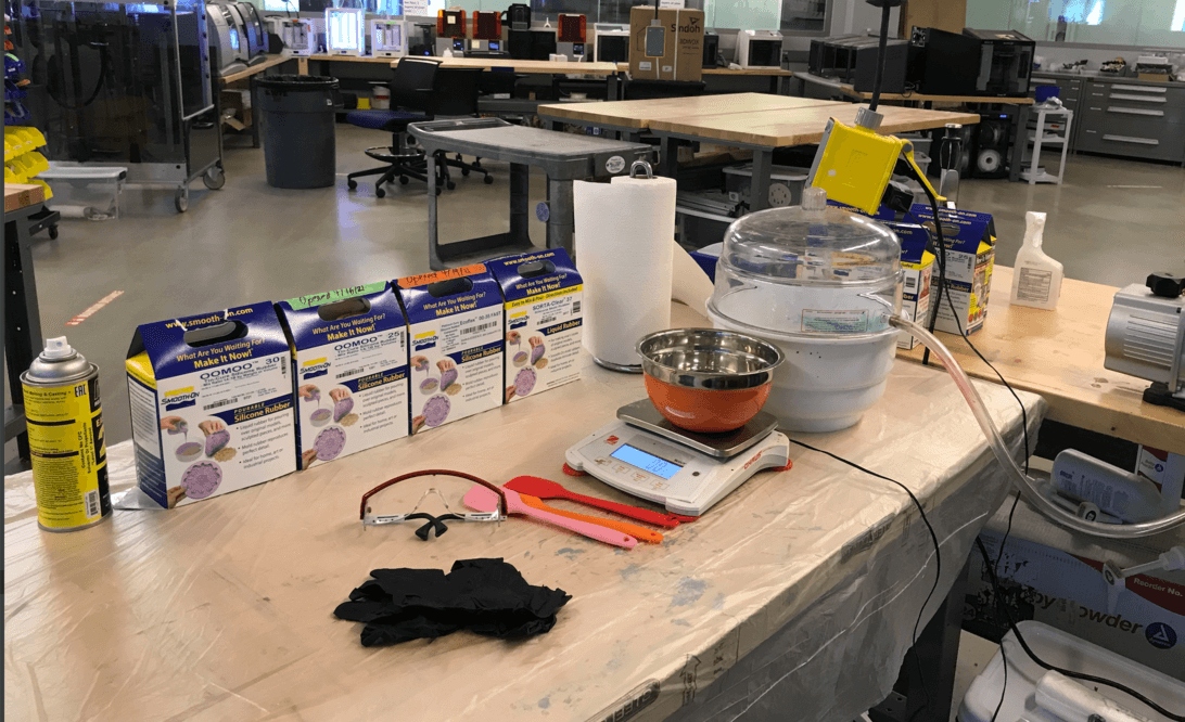
For this week's assignment, we were required to wear personal protective equipment (PPE) because mold making is a messy and potentially hazardous process:
- Gloves
- Masks
- Eye protection
- Aprons
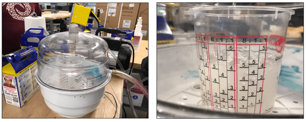
Griffin and Nick demonstrated a great way to calculate the amount of silicone for mold making:
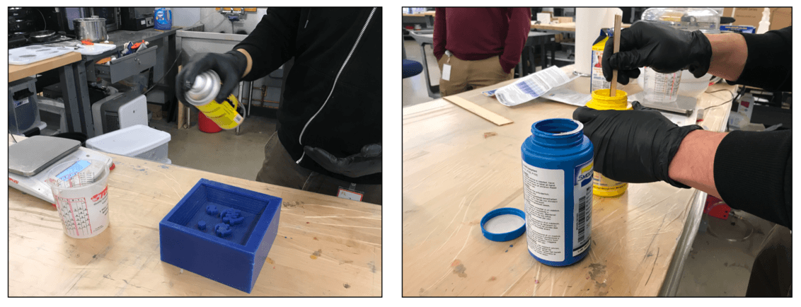
Greg had previously sprayed some release agent on the wax block and set it for 5-10 minutes. After we knew how much silicone we needed, Greg then opened the bottles of Part A and Part B and stirred them well before mixing:
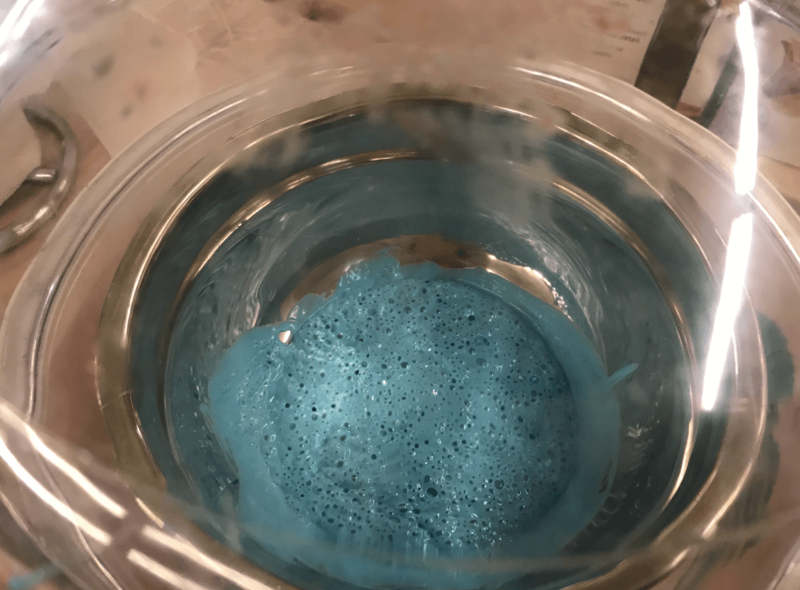
We used the vaccum defoaming machine to help remove some air bubbles:
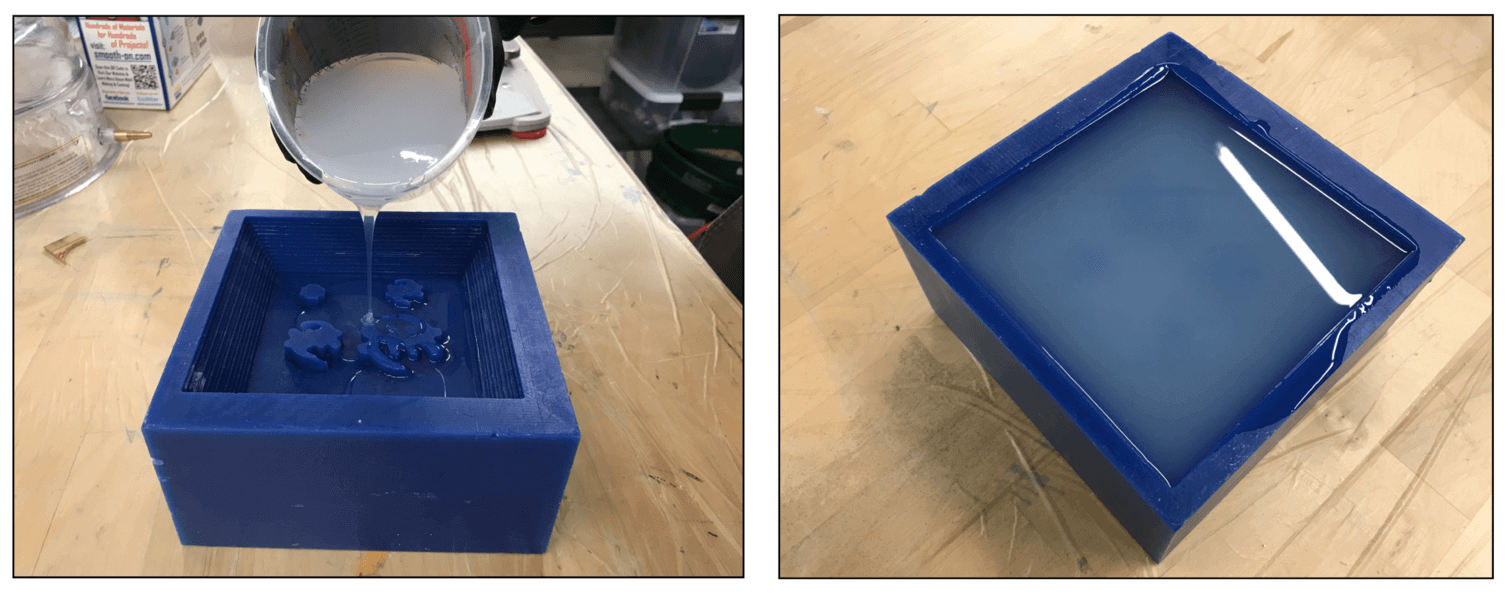
After degassing, Greg carefully poured the mixture into the wax block using a long thin beam:
We let the mold cure overnight, and here is the end result for the mold:
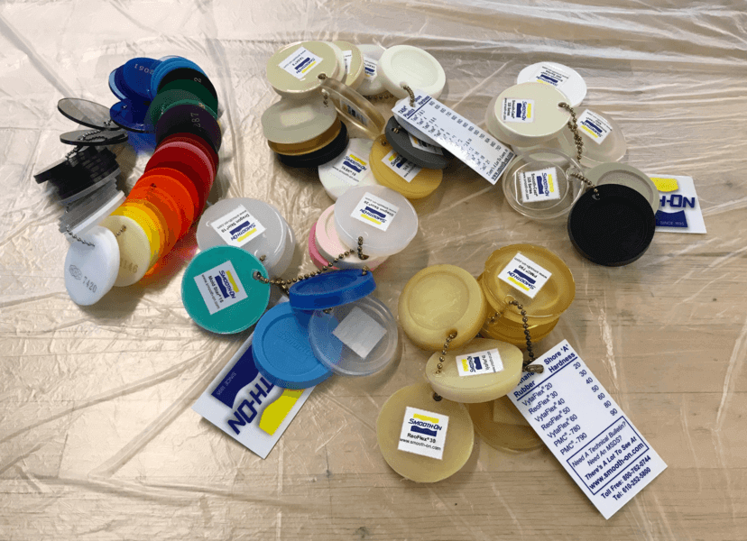
These are some other silicone materials that the lab had at the moment:
- Specific Gravity: 1.34g/cc
- Pot Life: 15 minutes
- Cure Time: 75 minutes
- Mix Ratio By Volume: 1A:1B
- Mix Ratio By Weight: 1A:1.3B
- Color: Light Blue
- Specific Gravity: 1.34g/cc
- Pot Life: 30 minutes
- Cure Time: 6 hours
- Mix Ratio By Volume: 1A:1B
- Mix Ratio By Weight: 1A:1.3B
- Color: Lavender
SORTA-Clear 37 (Food safe mold):
- Specific Gravity: 1.34g/cc
- Pot Life: 25 minutes
- Cure Time: 4 hours
- Mix Ratio By Volume: 1A:1B
- Mix Ratio By Weight: 1A:1B
- Color: Water White Translucent
I also found some silicone mold samples at the lab, which would be great for future references.
Mold Design
Apr 16, 2021Inspired by this Instructable tutorial, I decided to do a two-part mold in SOLIDWORKS for this week's assignment, and my initial design looked like this:
The design was more of 2D design and Greg had reminded us that we would need to make a 2.5D-3D design for this assignment as we would be milling a wax block using a roughing process followed by a finishing process. The roughing process was when the milling bit travelled in x-y directions, and the finishing process was when the bit travelled in z-direction. For this design, the outcome from the roughing process would look very similar to that of a finishing process, so I decided to re-design my piglet. Similary to my initial design, I used extrude boss / cut on features such as the ears, eyes and nose. To make my piglet looked more like a piglet, I chose to use style spline when creating the sketch of the ears and the face. I then used the revolve feature to create the 2.5D look of my piglet's head. Here is how my new design look:
Apr 18, 2021
Once I was happy with my design, I was ready to make the model for the wax block for milling. I planned to use the Roland SRM-20 milling machine for my design and I found that using the 1/8" Flat End (4 Flute) milling bits would work for this assignment. I double checked the parameters on the design and realized that the 1/8" bit would not be able to travel through the pig eyes and the nose as it was narrower than 1/8", so I made some small adjustments to ensure the design would work for the tool.
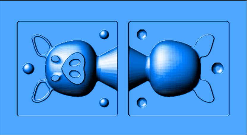
I used the split tool in SOLIDWORKS to split the object in half vertically and added three registers (the ball connectors) so that the molds could fit together firmly later. I also added the a "funnel" shaped spruce to pull the casting material and let the air out. Here is how the waxing block looked. I saved the .STL model of the wax block to setting the toolpaths in the CAM software (MODELA Player 4) of the Roland machine.
Later, during the weekly class review for this week's assignment, I learned from Neil that having a continous registation ring like this would actually work better than the post/ball shaped types of registers, as it would give a tighter fit and help reduce the size of the seam.
I also wanted to see what the mold would look like, so I used another subtract function in SOLIDWORKS to realize the shape:
CAM Settings
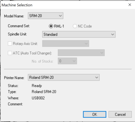
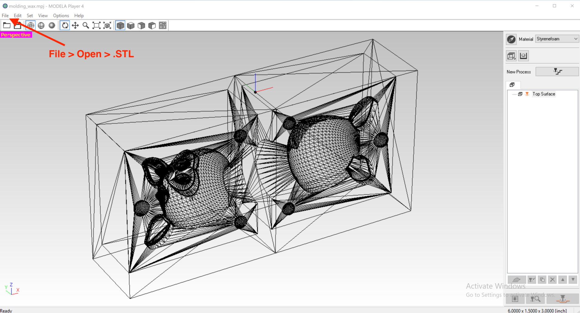
Apr 19, 2021I followed Yume and Toshi's documentations to create the tool paths in MODELA Player 4. The folder for the MODELA Player 4 CAM software is located under Desktop > SRM-20 Mini mill > MODELA Player 4 folder. Here are the steps that I followed:
- Select the correct machine: File > Select Machine > SRM-20
- Import the STL model of the wax model: File > Open > (**expand the list and choose the .STL model)
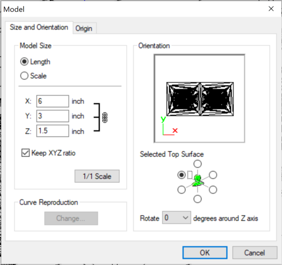
- Adjust the size and orientation of the model: Set > Model > Size and Orientation
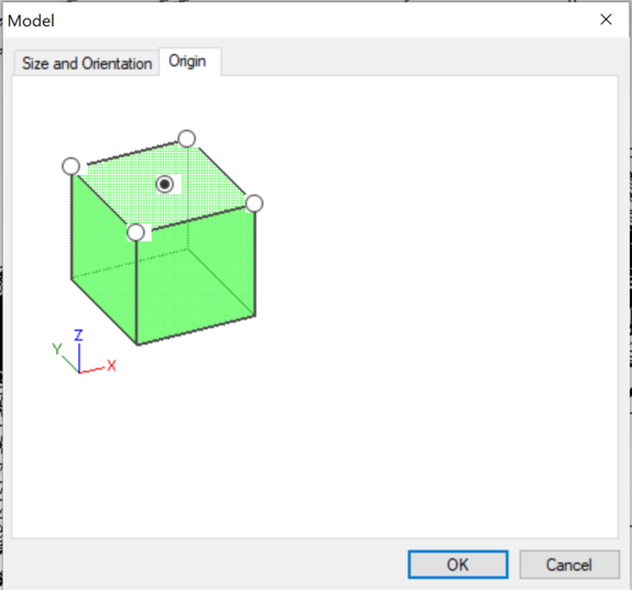
- In the Origin tab of the same pop-up window, make sure the origin was set to be center top
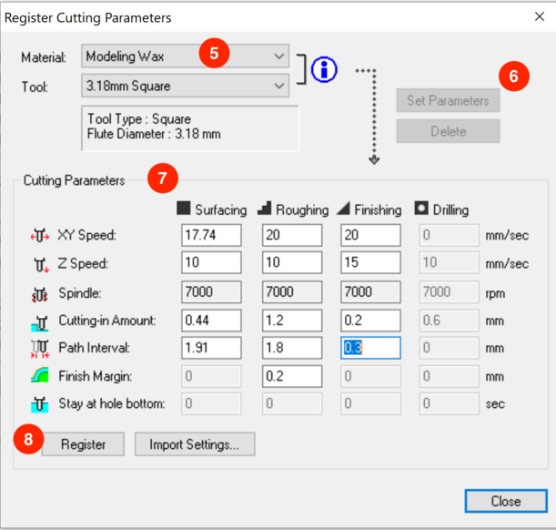
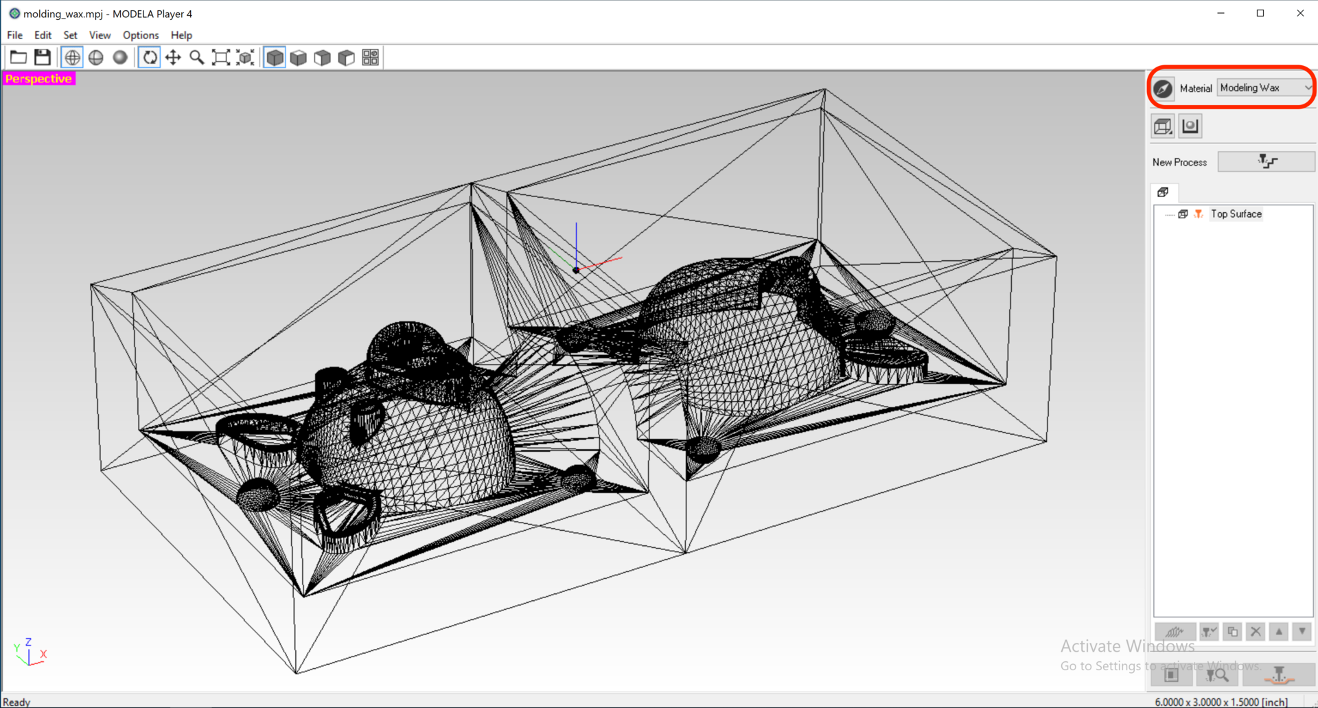
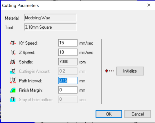
- Select Modeling Wax as the Material
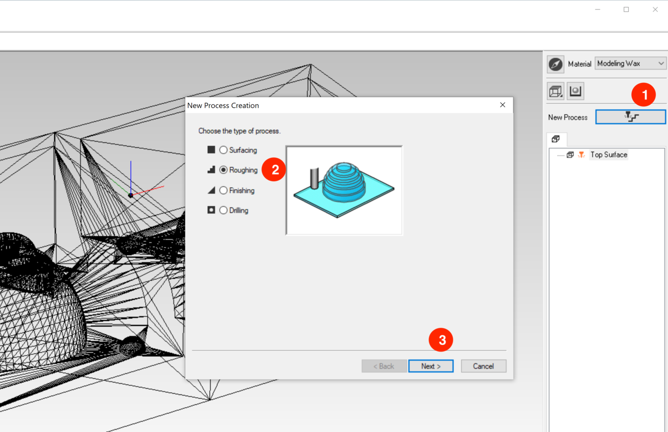
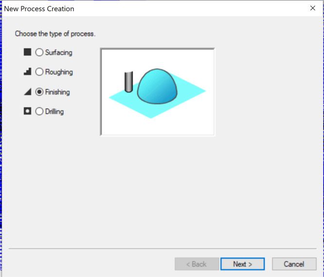
- Click the drill icon to the right of the New Process. Choose the type of the process > Roughing
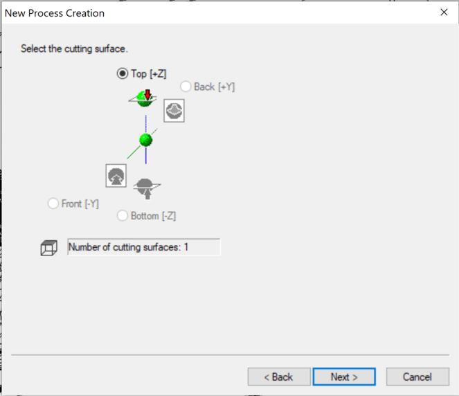
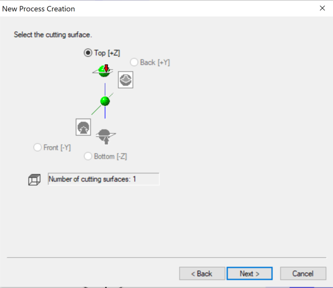
- Select the Top surface as the cutting surface
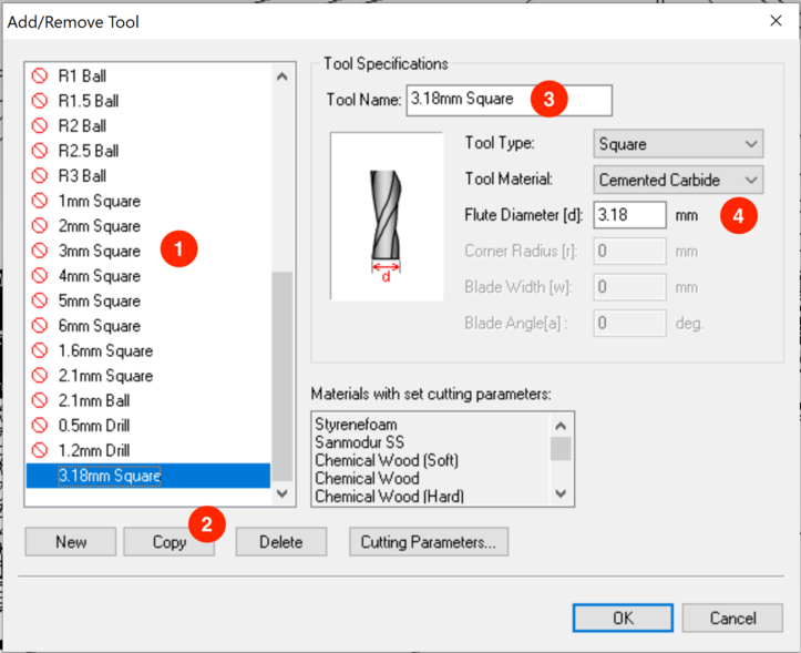
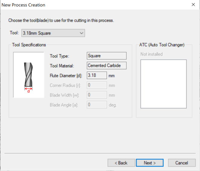
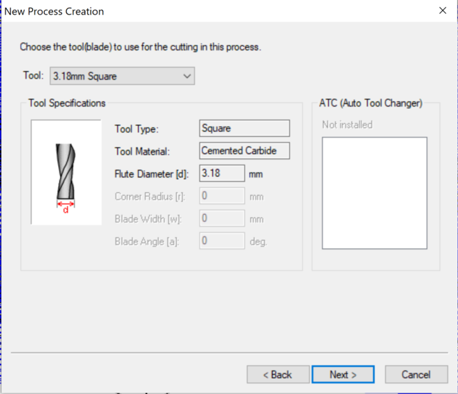
- Choose 3.18mm Square as the Tool
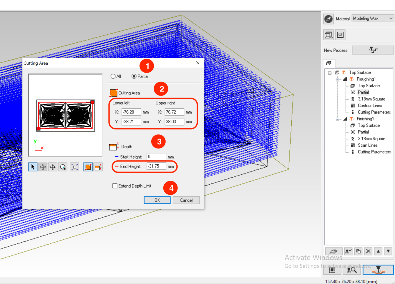
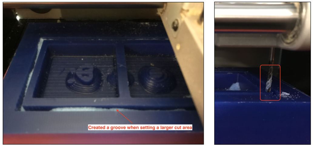
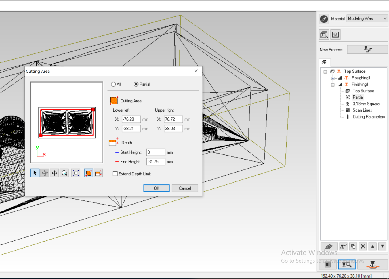
- (**Important**) Select the Cutting Area and Depth In the processing range, select Partial mode, and manually drag the red framming box to enclose only the area that I wanted the machine to cut, do not make it larger than needed!
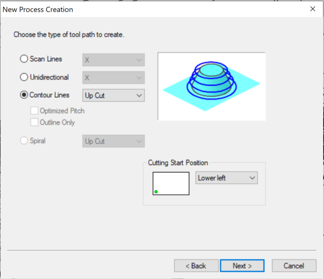
- Selected Up Cut as the Contour Lines, this is similar to using an up-cut bit in a ShopBot.
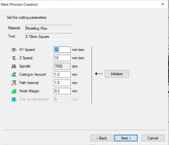
- Check the details of the cutting paramenters: XY Speed = 20 mm/sec, Z Speed = 10 mm/sec.
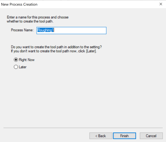
- Finally, set the name of the processing file as Roughing1 and click Finish.
- We can preview the process by clicking the magnifying glass icon on the bottom right panel of the UI.
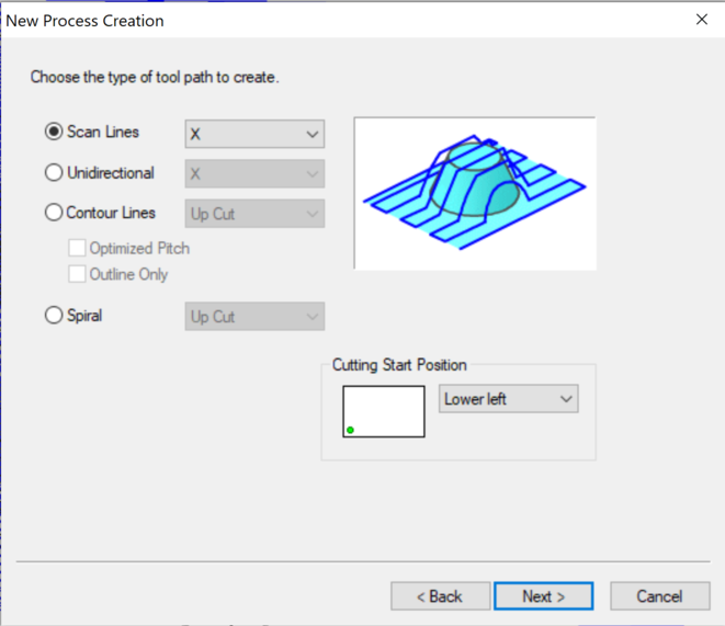
- Next, click New Process to create the toolpath for the finishing process. Select the machining type as Finishing.
- Select the Top surface as the origin / machining surface.
- Select the same Tool for finishing: 3.18mm Square
- Use Partial as the cutting type, and select the cutting area and depth manually.
- Set the type of toolpath: In the Scan Lines options, we could choose from X, Y, and X+Y
- Check the cutting parameter settings: XY Speed = 15 mm/sec, Z Speed = 10 mm/s.
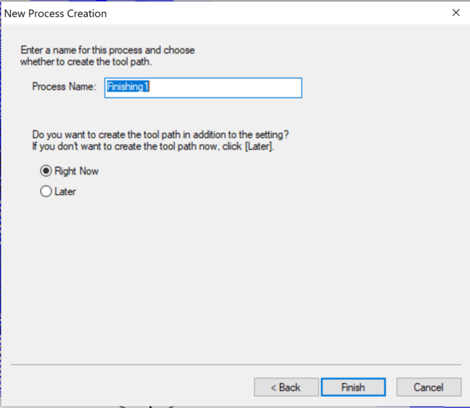
- Set the name of the process file as Finishing1. The estimated time for the Finishing process was 2 hours 57 minutes.
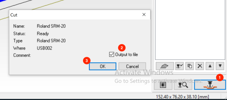
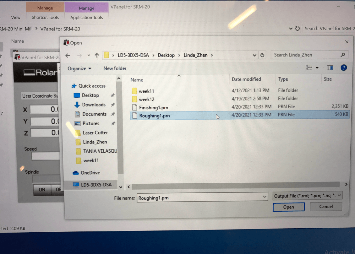
- Output the PRN file to read with VPanel for SRM-20: click the drill icon > browe to the designated folder set up for this week's assignment, click OK to save the Roughing1.prn file for the first window, then Finishing1.prn file for the second window.
In my case, the 1/8" Square 4 Flute milling bit that I would be using was not on the list, so I needed to add it first: Options > Add/remove tool > **copy the 3mm Square bit and renamed the new bit as 3.18mm Square > **set the informatin for the bit:
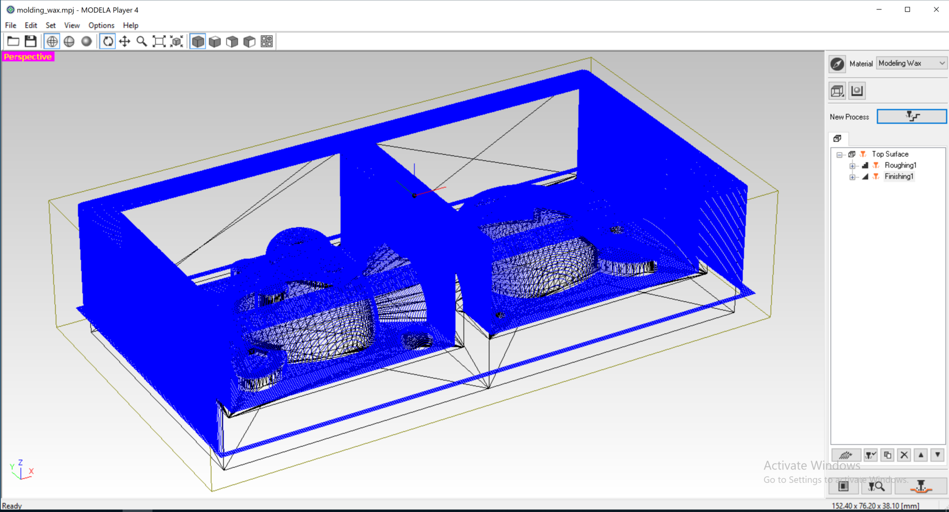
From here, we will creat the CAM Process: first the Roughing process, then the Finishing process
I made this mistake the first time and ended up trapping the milling bit in the "groove" that it created for the cut area, as a result, causing an emergency stop by the machine. It was 2 hours into the milling process but becasue of the emergency stop, I had to turn off then turn on the machine in order to be able to move the milling bit to its home position. However, all the previous milling data was lost and I had to restart the process on a new machinable wax.
Here is the generated toolpath for the roughing process:
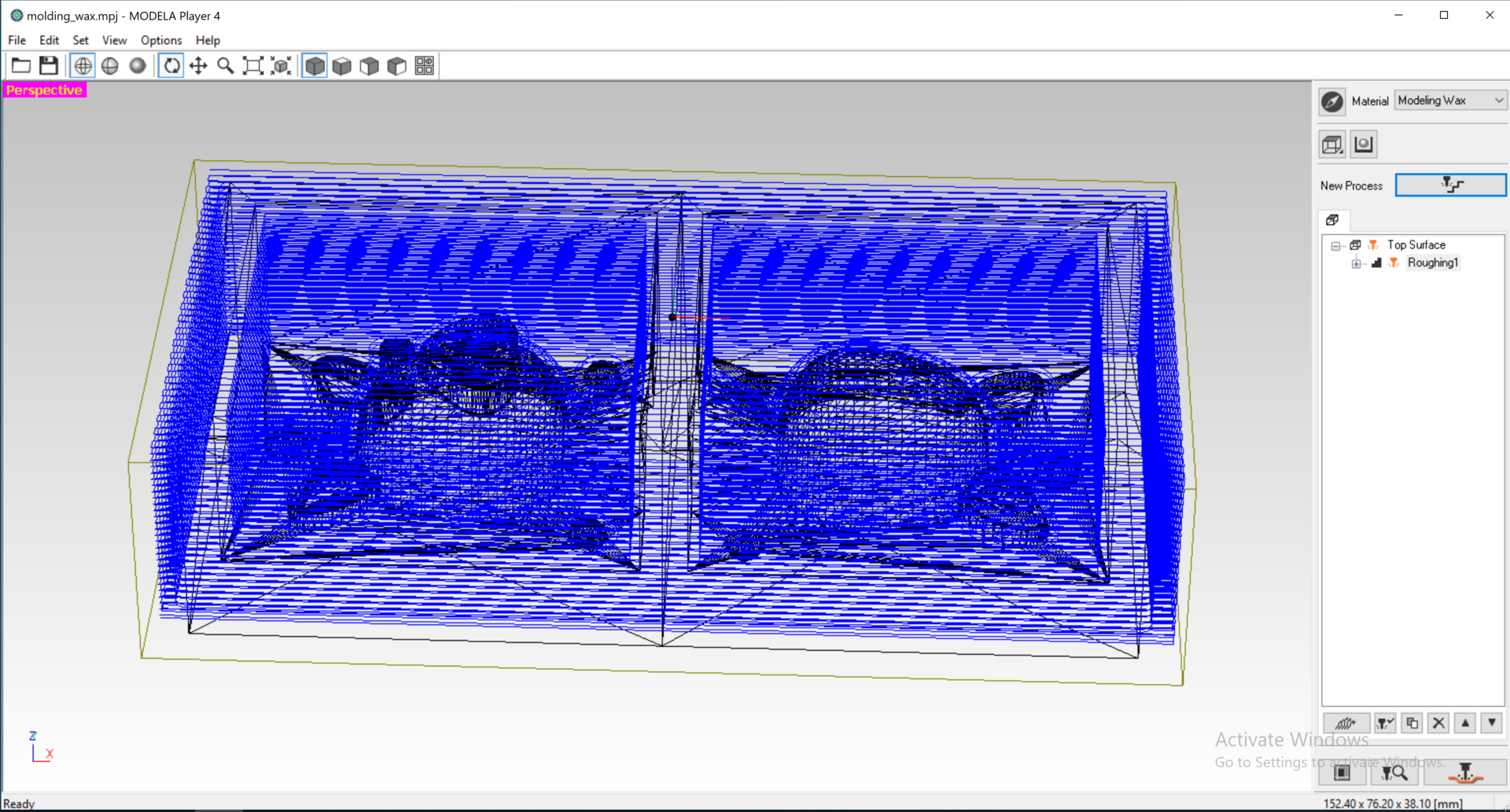
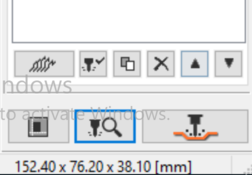
Press OK to display the cutting preview. The estimated cutting time for my roughing data was 1 hour 47 minutes. Which was pretty accurate based on my experience!
Here is the simulation result for the roughing process:
I played with the three types of scan lines, and based on the previews for this process, I found that Scan lines: X would give me best result for my design.
The default Path Interval (stepover) is 0.3 mm, but I found the finishing surface looked similar from the result of the roughing process, so I reduced the Path interval to be 0.15 mm in my setting.
Here is the simulation result of the finishing process (Scan line = X, Path interval = 0.2 mm) for my design:
**Important**: It is better to double check the file sizes to make sure the output files were correct. For reference, my Roughing1.prn file was 539 KB, while my Finishing1.prn file was 2MB.
Milling My Mold
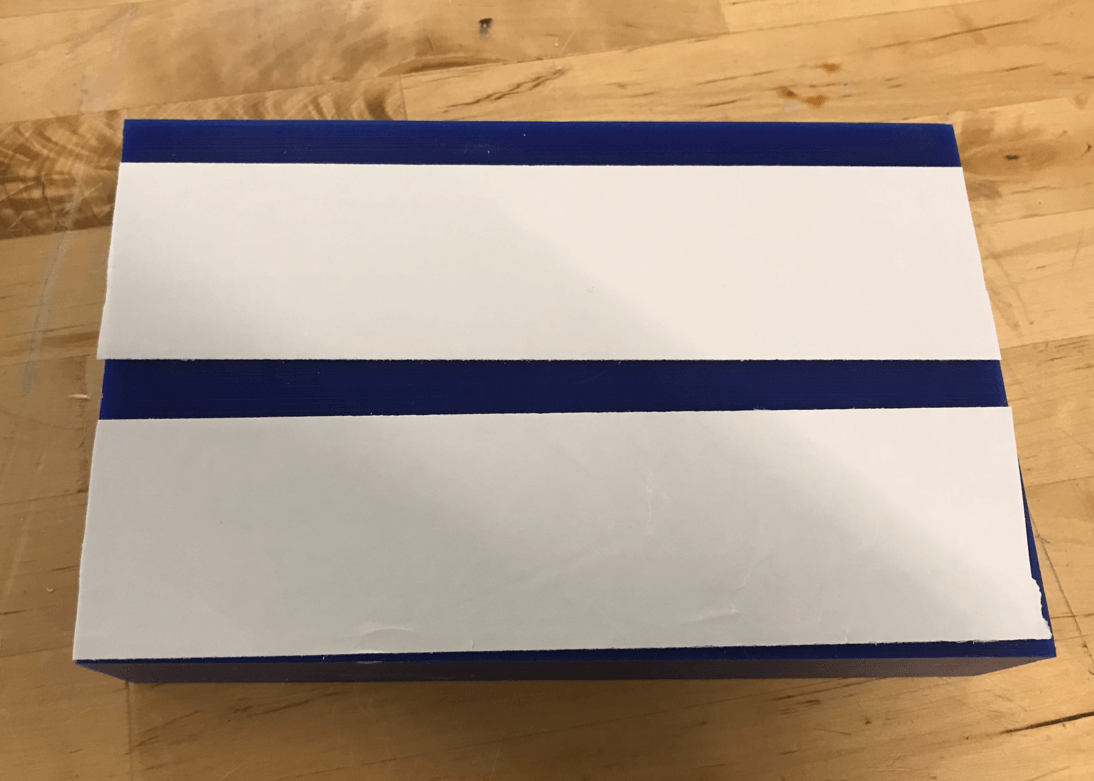
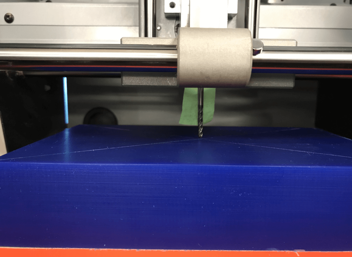
Apr 20, 2021For this assignment, I needed to first remove the wooden sacrifical board that was taped on the surface of the machine to allow for enough room for milling the machinable wax. I used double sided tape to secure the machinable wax to the surface of the machine. I then followed Toshi's set up to get the correct position of the origin (i.e. drawing a cross mark on the center of the block) and the 1/8 SE 4FL milling bit (i.e. use a 35 mm long tape to define the attachment location of the milling bit to the chuck).
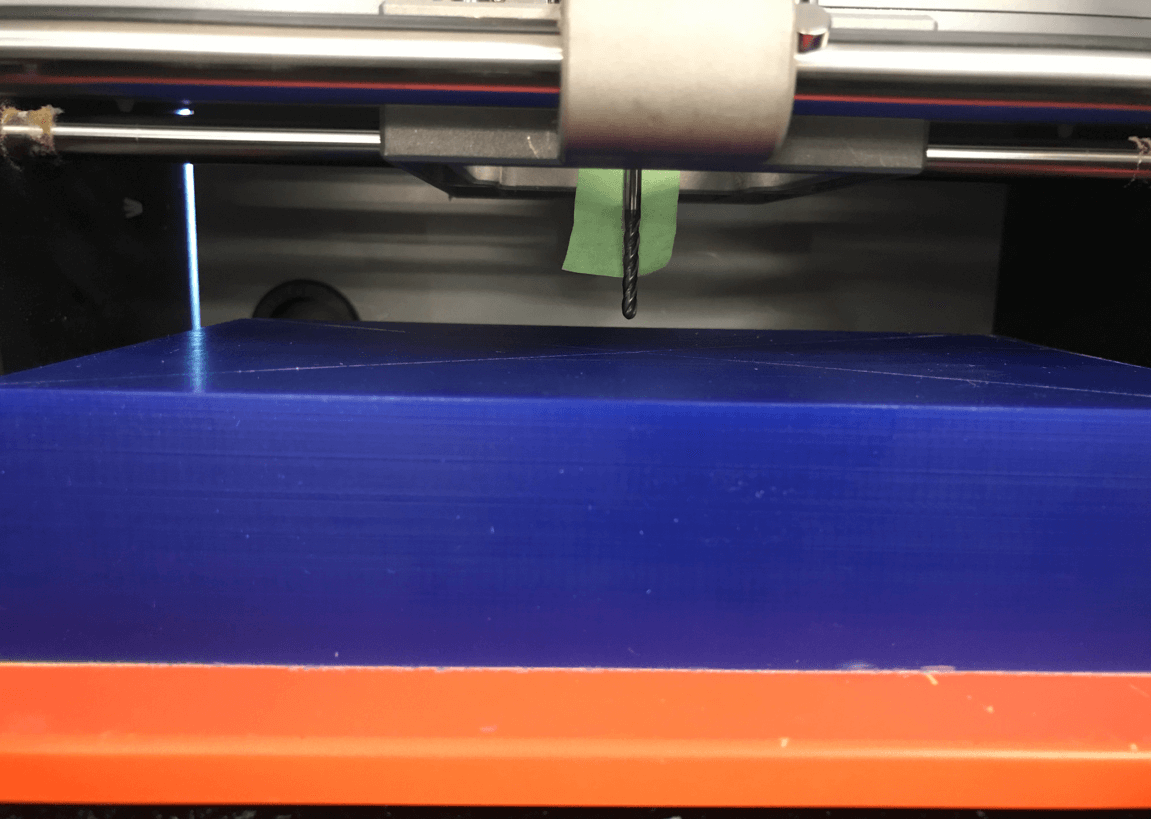
After that, I followed a similar process in the Electronics Production week to drive the milling bit and set the origin position on the crossing mark. After that, I removed the green tape from the bit.
Next, I click Cut to load the PRN file created earlier. I clicked Add, and selected the Roughing1.prn file. Then press Output to start cutting.
Here is a short video of the "roughing" process. During the process, I paused the machine from time to time to vacuum the shavings so as to minimize the chance of the bit getting clogged up. I had made sure I could do this by running some tests before running the actual file.
The roughing process took 2 hours, which was pretty close to the estimated time by the CAM software. When the milling machine stopped, I noticed that the milling bit stayed above its last stopping location, which was unusal to me. I consulted my instructor Spencer and he informed me that, usually the bit would go back to its home position. I then checked the VPanel software and double checked my block, and knew that the process didn't encounter an error, so I thought this was probably the case when the Roland machine using the same bit for both the roughing and finishing processes. After that, I used the Move to Origin buttons on VPanel to drive the bit back to its origin, then used the same process to run the G-code file for the Finishing process.
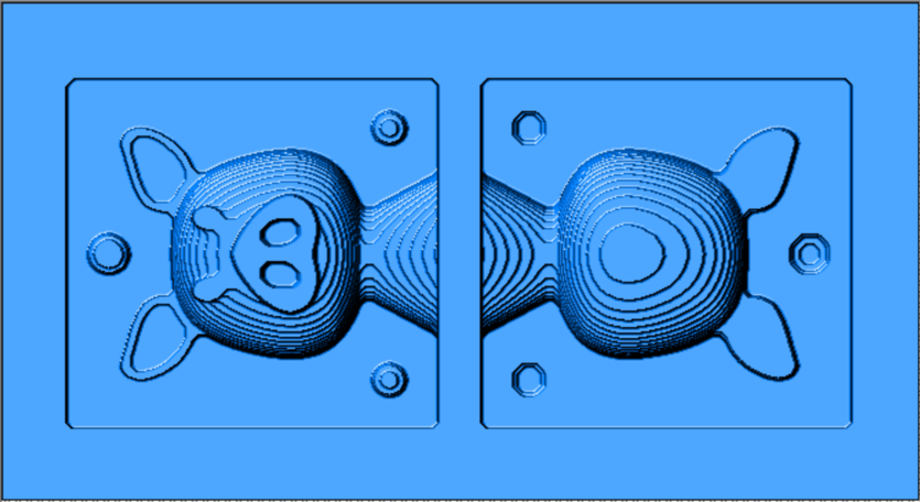
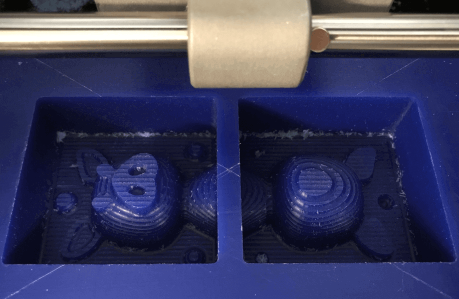
Here is the result of the "roughing" process:
Here is a short video of the "finishing" process
Here is the result of the "finishing" process, I was very happy with the surface finish!
Molding and Casting
Apr 20, 2021Initially, I planned to made a food safe mold using SORTA Clear 37 silicone molding material, however, due to time constraints (it was 5:30PM on Tuesday), I switched to use OOMOO 25 becuase its curing time was only 75 minutes instead of 4 hours.
Since the pot life was only 15 minutes, I must use the time wisely. I had set up the molding and casting area like this, everything was within reach:
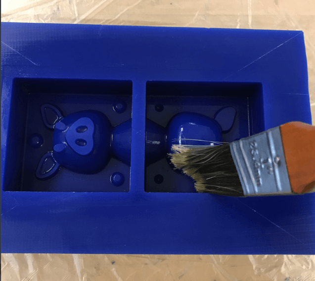
I also applied release agent on my waxing block twice: first coat by brush, second coat spray on and let it set for 30 minutes.
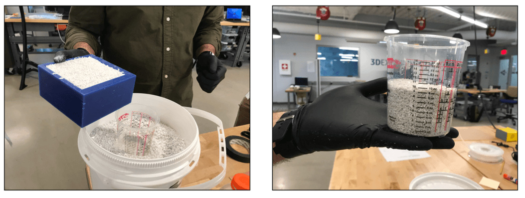
I had brought some rice from home to measure the amount of silicone I would need.
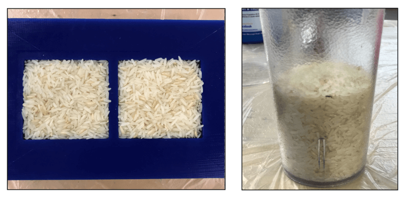
It seemed that our lab had ran out of measuring cups, so I borrowed a mixing bowl and a cup from the Fabricacademy program for measuring and mixing my materials.
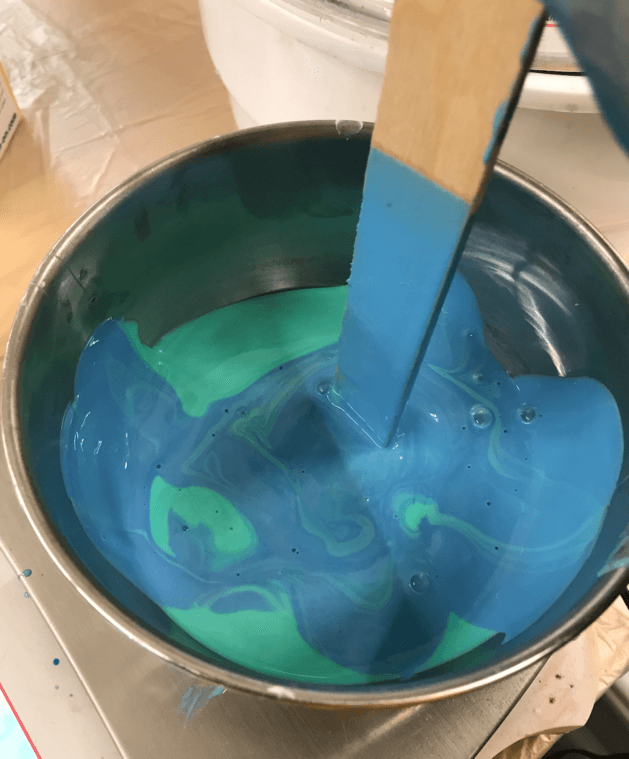
There were many air bubbles generated during the degassing stage.
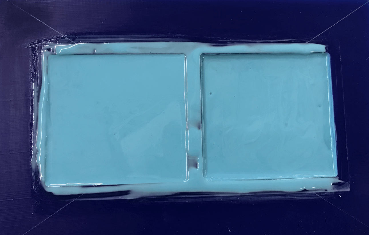
Even though I had added more materials than I calculated for the mold, I should have added even more since the material was quite viscous and some last bits still stuck on the bottom of the bowl. Here is how the mold looked before curing:
It was almost 6PM when I finished pouring the molding material and cleaning the area, so I would need to wait until 7:15 PM to get my mold cured. However, when I checked at 7:15 PM, I found that my mold was still a little wet, so I decided to stay at the lab until after I finished the zoom meeting with my professor, which would take place at 8 PM.
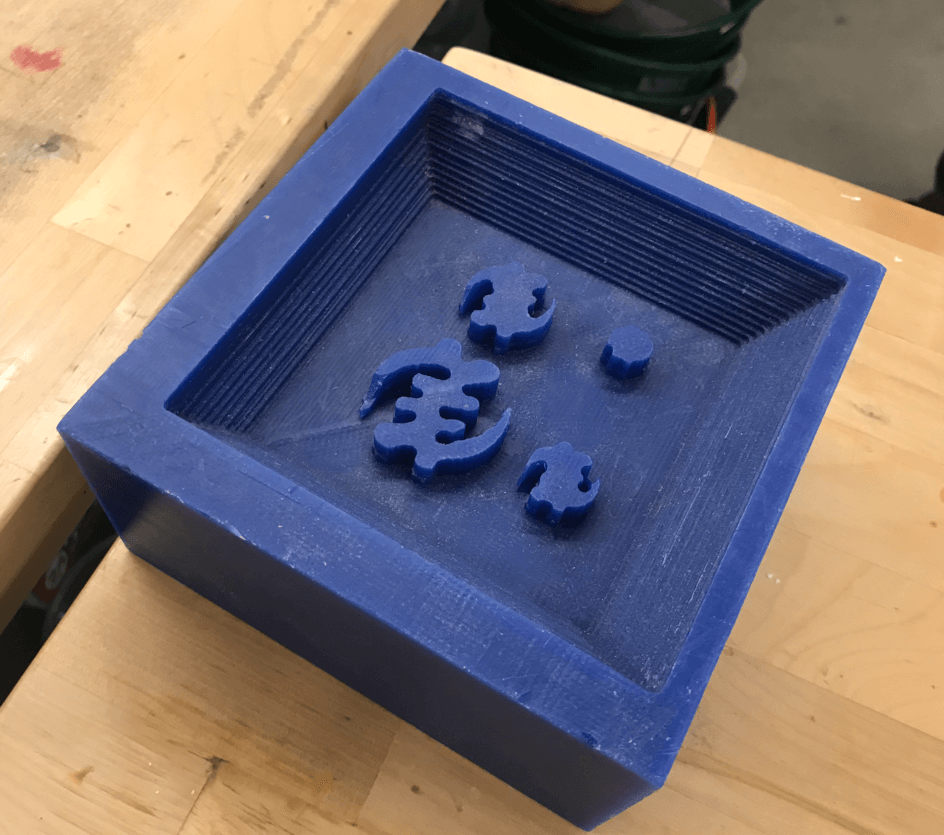
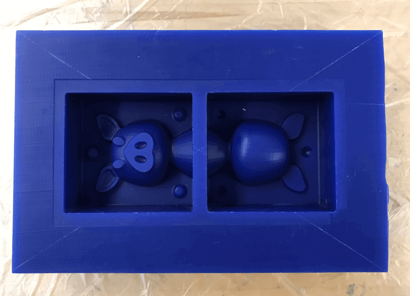
Here is how the mold looked after curing. As shown in the image, I didn't pour the mixture well enough and left two air bubbles on the pig nose, I hope this would not be a big issue in the casting stage. 😅
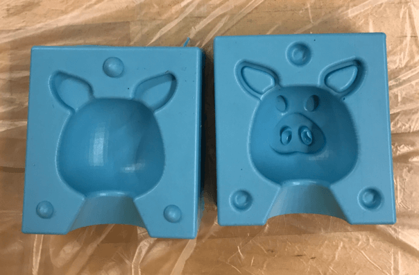
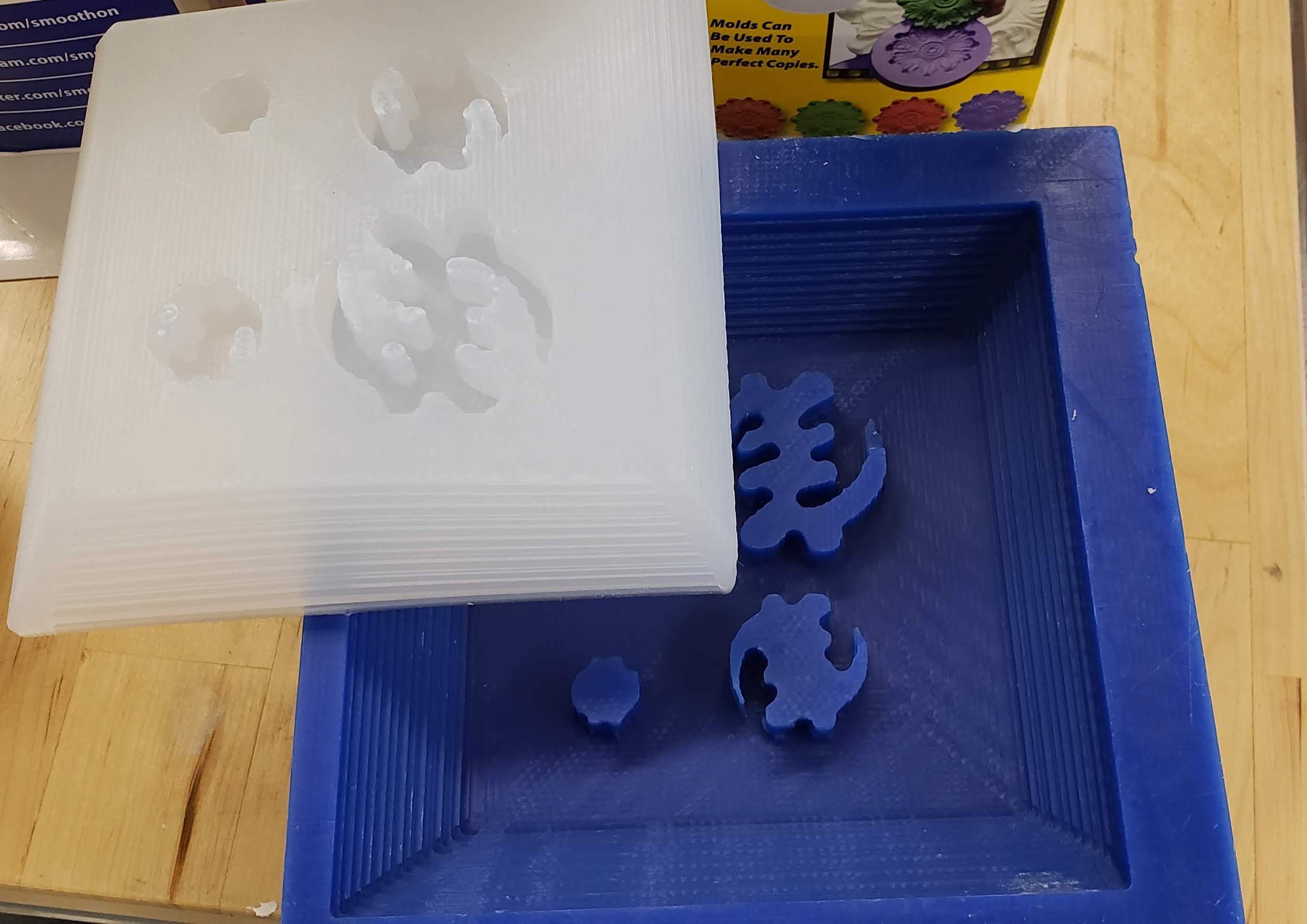
Forutnately, the molds fit nicely. The ball shaped registers did help!
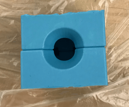
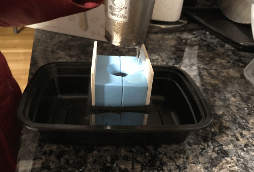
I had previously cut out two small supporting pieces out of a 3mm plywood for the casting stage. At around 8:30 PM on Tuesday, I left the lab and planned to cast my mold for an ice piglet at home. Since I didn't use a food safe mold, I must be careful and not to contaminate other areas in the refrigerator. Fortunately, we had a separate freezer where my mold could stay overnight. Here is my mom help pouring some Chinese tea into the hole of the mold for casting. We wanted to see if the color of the Chinese tea would show up on the ice piglet.
Apr 21, 2021
I got up early today to check my casting piglet. We found that the ice exploded a little bit.
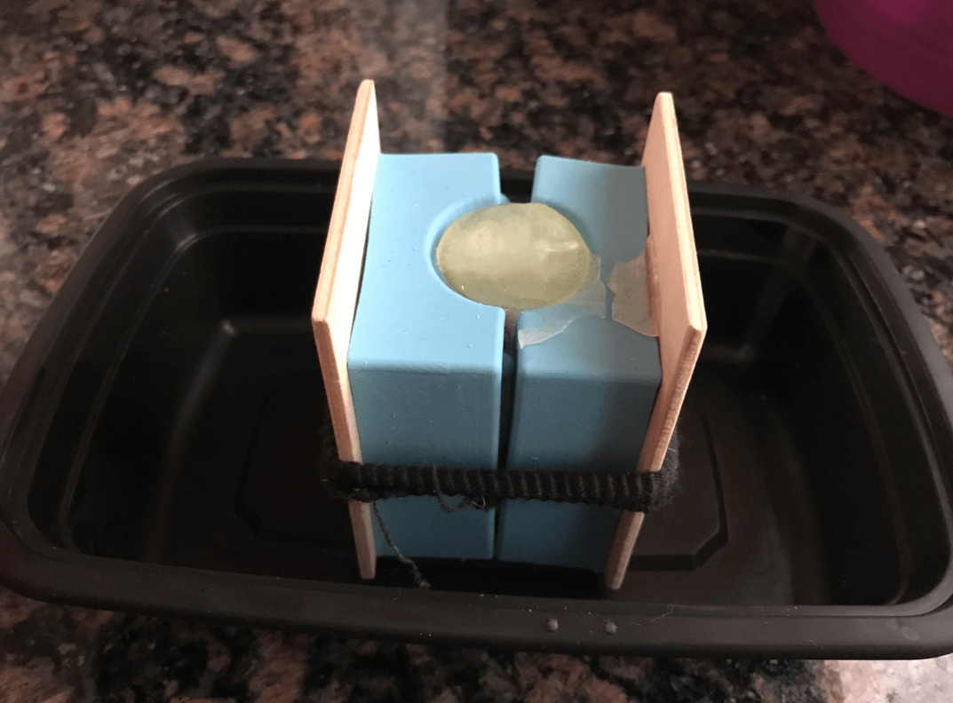
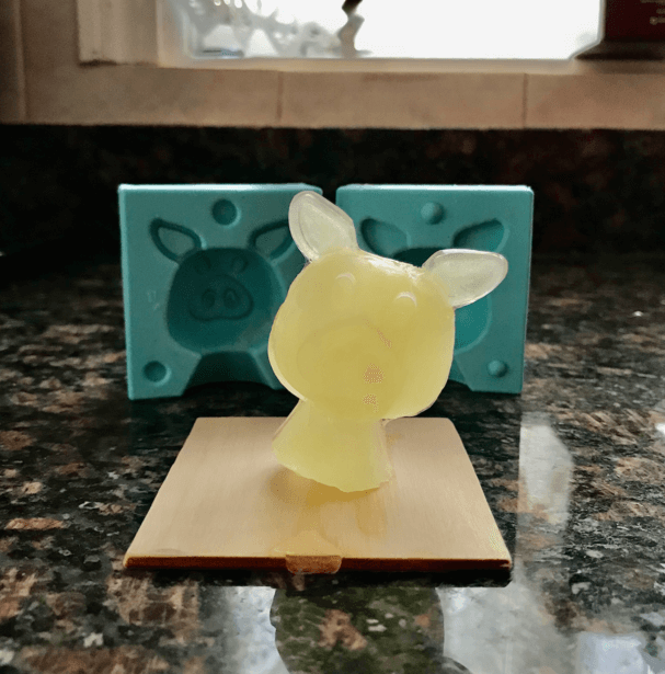
And here is how the ice piglet looked:
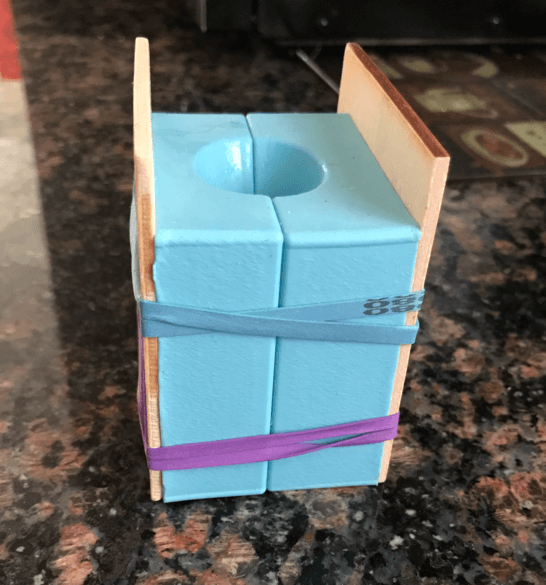
There was a crack on the left side of the pig head, most likely because I didn't tie up the wood pieces well enough since I was only using one hair band and also positioned the mold in the center of the board (, which made the assembly even more loose). I then switched to this types of elastic bands, and was ready for more ice piglets.
During the weekly class review for this week's assignment, Erwin from Waag FabLab recommended us a great food recipe mold making book - I would definitely want to test them on my mold someday!
Files
Please find below the files that I made for this assignment.
- Pig .STL File
- Modeling wax .STL File (this is the file for milling)
- Mold .STL File
- Original SOLIDWORKS Design Files (part and assembly models)
- G-code files for milling (Roughing and Finishing Processes)