15. Molding and Casting
Assignments
- Group assignment:
- review the safety data sheets for each of your molding and casting materials,
- then make and compare test casts with each of them
- Individual assignment:
- design a mold around the stock and tooling that you’ll be using,
- mill it (rough cut + (at least) three-axis finish cut),
- and use it to cast parts
Group assignment
Check out the FabLab Kamakura 2020 site page.
Individual assignment - mold a cap for a tactswitch
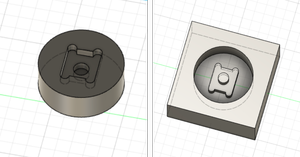
For this week’s individual assignment, I decided to make a larger cap for a tactswitch, as a part of my final project installation.
In my final project, there is a control panel to control the temperature, flow, etc. of the mini salt factory.
I want to make big and rather dramatic buttons for a more interesting interaction.
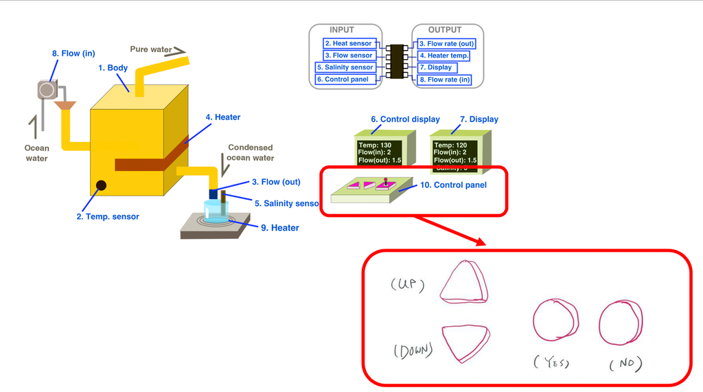
There will be 4 buttons in total, 2 triangle ones for up and down to adjust the numbers, 2 round ones to confirm or cancel the action.
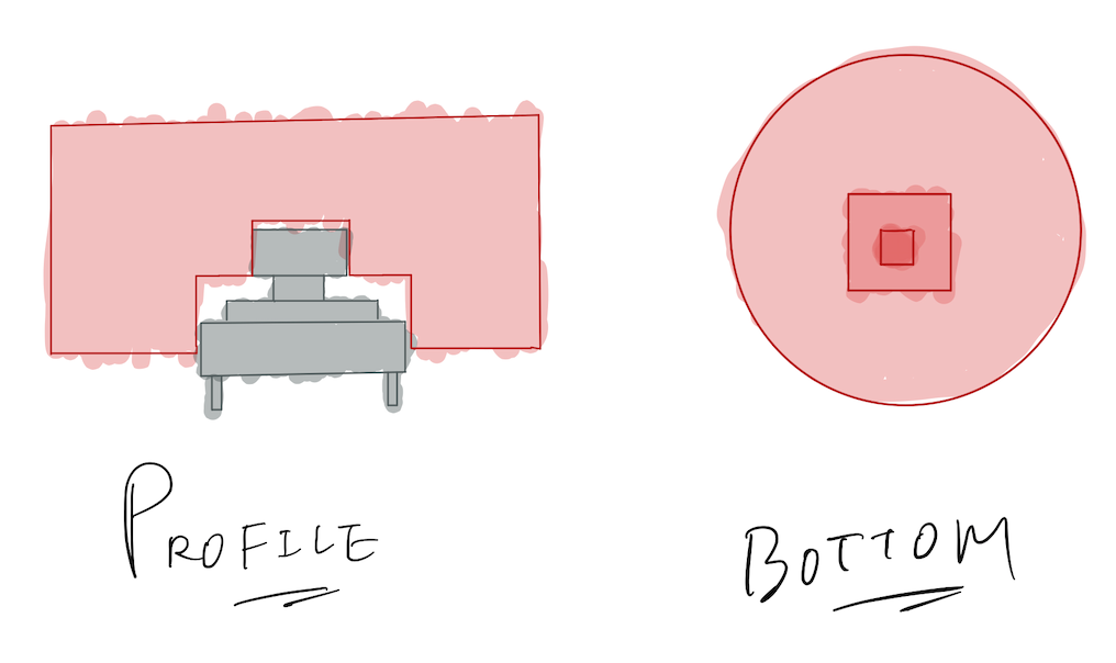
Research on existing tactswitch caps
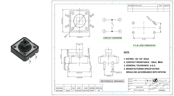
I looked into existing tactswitch cap products to study the structure.
The tactswitch I want to use is a 12mm one (TVGP01-G73BB) made by Zhejiang Jianfu Electronics Co., Ltd.
The datasheet can be found here
I found 2 different kinds of cap for it.
The first one’s datasheet is here and the second one’s is here.
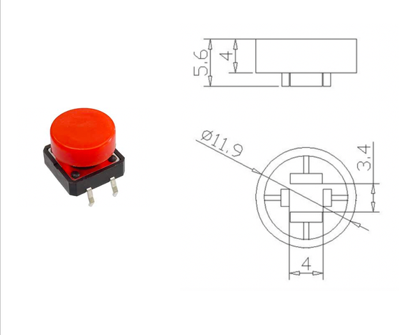
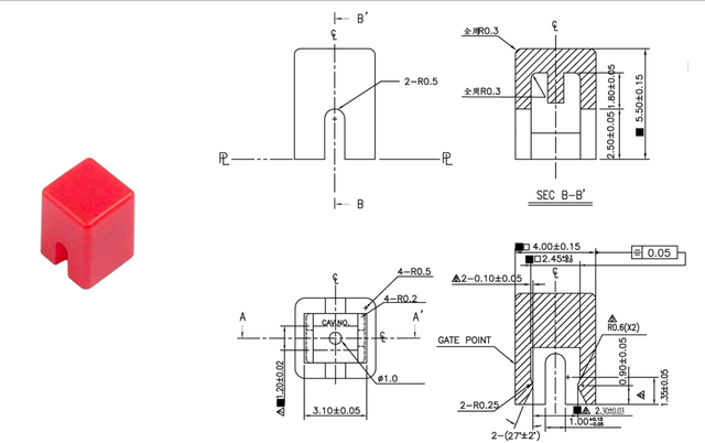
The basic concept is to have a narrow space to cover up the button part, and leave enough space between the cap and the surface so you can press down.
Design the cap
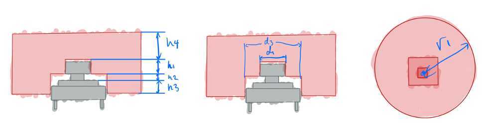
This is a simple and functional design I thought of based on the research.
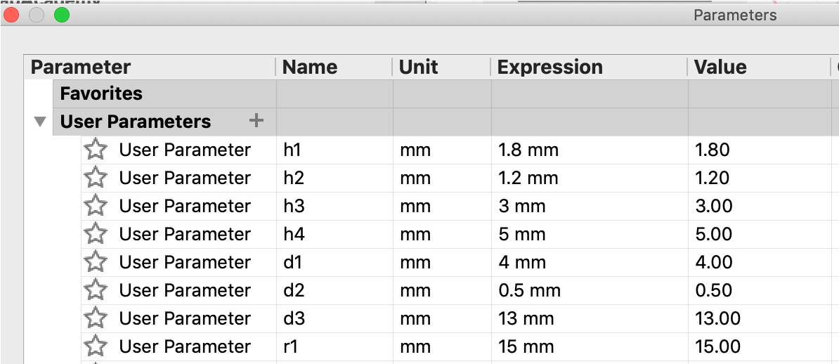
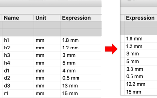
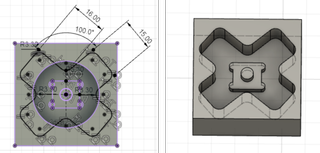
I used Fusion 360 to model. And I set up these parameters for the design.
Model the mold
Model the actual body
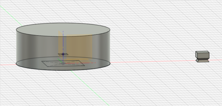
I started with modeling the actual body before modeling the mold.
I made a cylinder, and made the shape to cut out inside the cylinder.
At first, I made a slightly more complicated shape.
Although I simplified the design in the end, I still learned something new - loft feature.
This feature connnects 2 profiles to make a 3D figure.
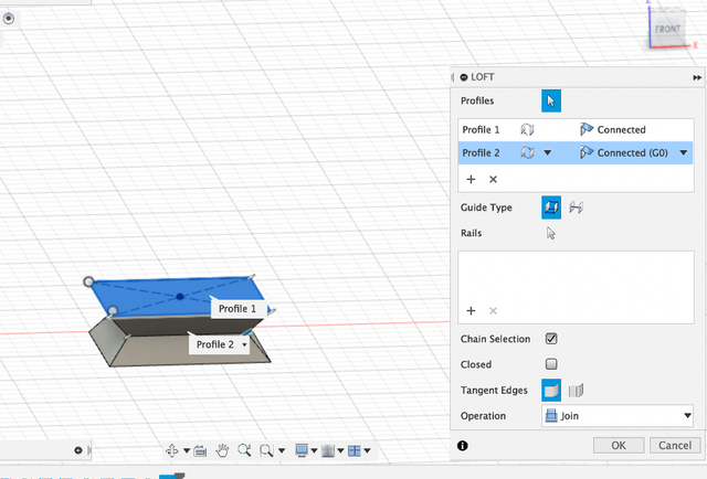
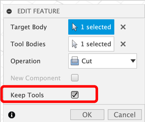
Then I used cut in combine feature to cut the cylinder using the small figure.
When “keep the tool” is ticked, the figure used to cut would remain instead of disappearing.
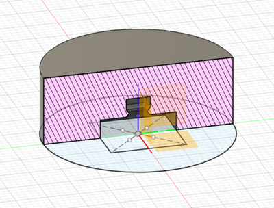
And this is the sectional view of it.
Model the mold
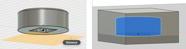
I created a rectangular cube from an offset plane slightly under the actual body.
And then I used the actual body to cut inside the cube.
Then I created a middle plane in the cube, used “split body” in “modify” to split the cube into half.
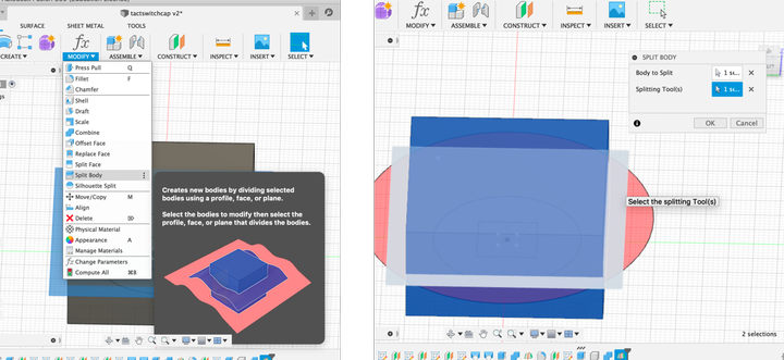
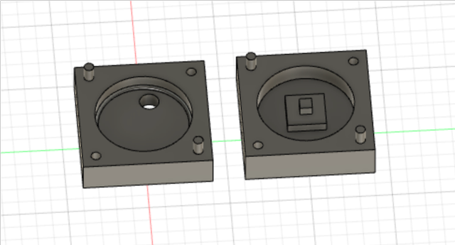
I used “hole” feature to make 2 holes, and added 2 cylinders so 2 parts of the mold can close up tightly.
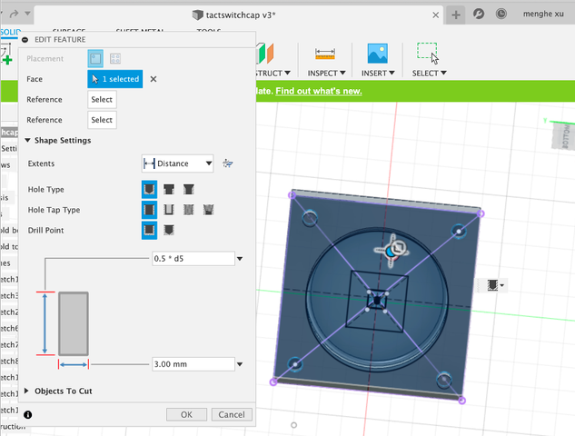
And I added a hole for injection. (Then I realize that I needed another one to let air out.)
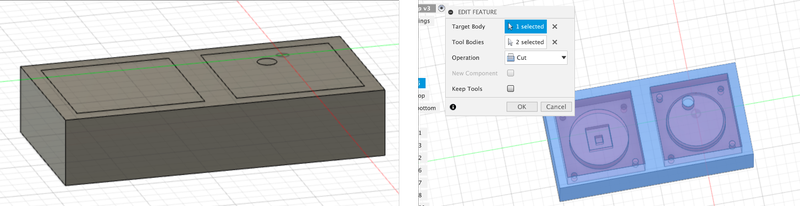
Model the mold of mold
I created a larger rectangular cube that covers up the mold, and use the mold cut the cube.
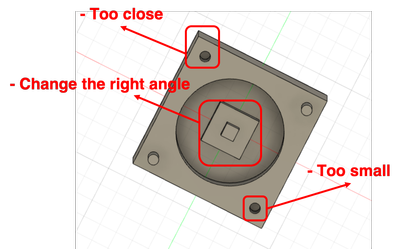
Debug the model
After the instructor’s check, I find out that my model had some issues:
-
Actual body
-
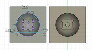
The mill’s diameter is 3.18mm, so it can only cut sizes above that. The hole and the edge are too close right now, so I added some distance between them.
-
The holes to fit the upper and bottom molds are too small (diameter is 2mm now) to mill.
-
The right angles can’t be created with the 3.18mm mill, so I changed the inned square into a circle, and added dog bones to the outer square.
-
-
Mold
-
There needs to be 2 air holes. One to inject the material, and one to let air out.
-
The air hole is now on the top of the body, and that would make the figure not as beautiful. It’s better to have them on the bottom.
-
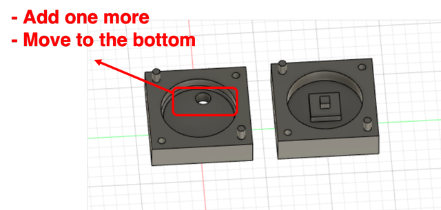
- Mold of mold
- Now the longest edge is on Y axis, and it needs to be on X axis to cut (it seems that you can change that in MODELA PLAYER also.).
This is the mold of mold after the modifications.
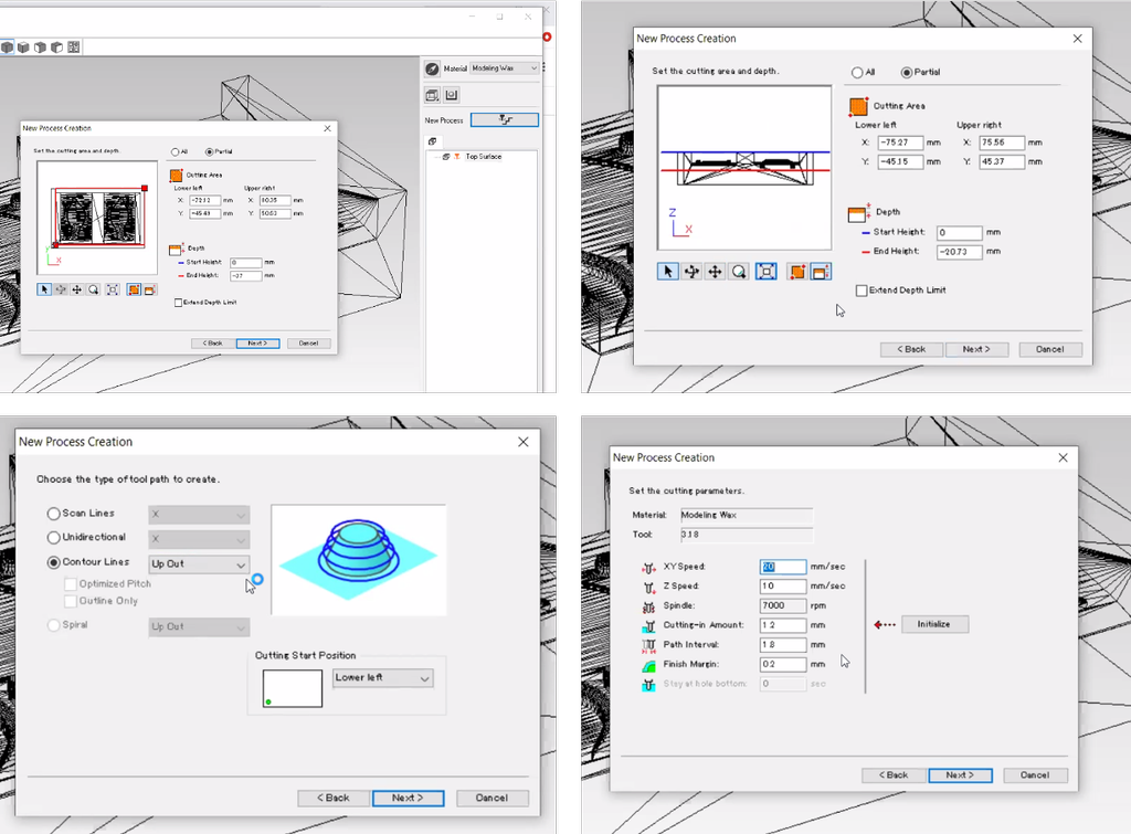
Remote control - Create tool path
In April, since we didn’t have lab access because of the pandemic, I used Modela player through remote control on the lab’s laptop.
I exported the mold of mold to stl file, and opened it on Modela player.
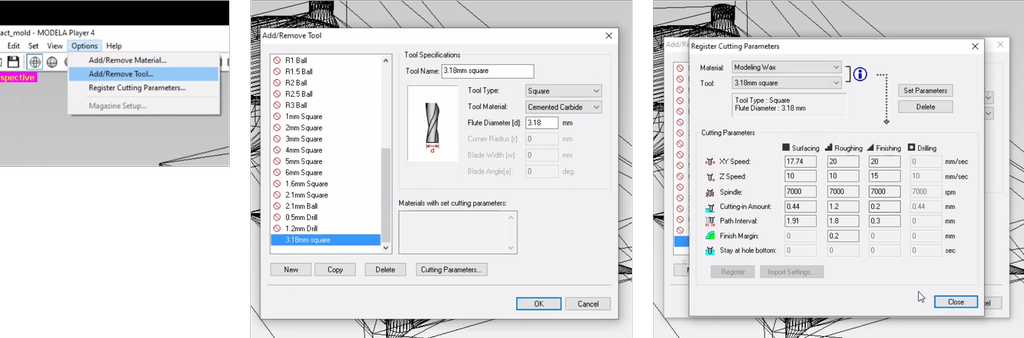
Add tool
1/8 inch square mill needed to be added since it’s not in the tool list.
“Options” > “Add/remove tool” to add 1/8 inch square mill. The material was set to modeling wax.
Roughing
Roughing process’s tool path was created based on using a 1/8 inch square mill.
“New Process” > “Roughing” > “Partial” to select the part to generate tool path > “Contour lines”: Up cut > Set the parameters.
Here is the preview:
Finishing
Finishing process’s tool path was first created based on using a 1/8 inch square mill.
“New Process” > “Finishing” > “Partial” to select the part to generate tool path > “Scan lines”: X > Set the parameters.
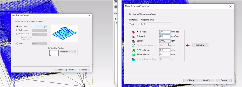
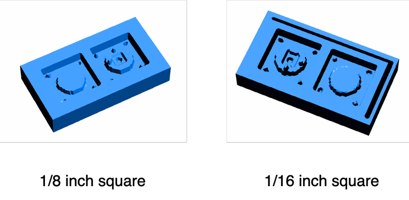
The 3D preview seems pretty rough, so I tried simulating using 1/16 inch square mill but it didn’t seem different much.
Advices for improvement
I got some great advices at Asian review and will work on them:
- I can add marks onto the top of the cap.
- To make my surface smoother: since I have flat surfaces and vertical surface, it is better I do scan lines + contour in the finishing process. Contour follows the perimeter of my object and if the face is vertical, then it would be milled super smooth.
- For the hole to pouring material, its better to make it a cone shape instead of a cylinder shape so it will be easier to aim at the hole when pouring.
- If the hole is large enough (over 6mm), the air vent is not needed.
Test - cap made with 3D printer
I managed to sneak the Adventurer 3 in my office home, so I tried to print the cap out to see if it fits on a tact switch.
And it turned out to work! A bit loose though…
Model revision
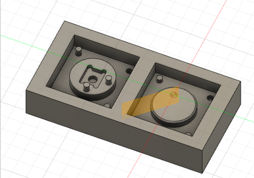
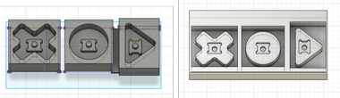
I decided to have 3 different shapes for my button - triangular, circular, and cross-shaped.
The machining was I am using has a dimension of 92.1 x 152.4 x 38.1 mm, therefore, to mold all 3 shapes with 1 block of wax, I decided to only do 1 side molding instead of 2 sides and have the mold of 3 shapes all created on the same wax.
On Fusion 360, I disabled filet on the model of button, created a cube from the surface of the bottom of the button, and used the button to cut the cube.
Also I changed the dimension (made d1 and d3 smaller) since when I tested with 3D printing, the cave to fit on the tact switch was too big that it was unstable on the switch.
To make a triangle shape, I sketched directly onto the bottom of the round-shaped button’s mold.
I drew a triangle and added filet to the edges.
Then I used extrude create the shape.
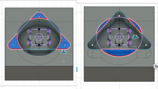
I used the same technique (sketch a cross and added filet to the edges, and extrude) to make the mold of cross-shaped button too.
I know it’s not the most elegant way to do it, but it does the work!
As I mentioned before, since the end mill has a diameter of 1/8 inch (3.175mm), I made sure no path has a dimension less than that by using the Inspect function to check the dimension. The filet has a diameter of 3.3mm.
Then I adjusted the sizes a bit, created a cube that is smaller than the machining wax, and cut it using the molds.
Create toolpath
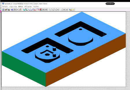
In June, I was able to get into the lab to actually mold and cast.
The process of creating toolpath was the same as stated before in the remote control session.
Besides those, there were a few thing that I learned when I actually get to mill in the lab.
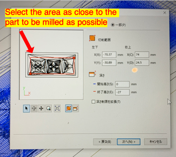
It is better to select the milling area to the pattern to be milled. If you include the surface that does not have pattern on, the mill still go through it, so that is time consuming.
Also for z axis, during finishing, since I only needed to finish the button part, I should’ve lower the milling area to there.
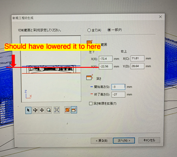
This is all because the milling process is very time consuming (for me it was more than 2 hours), so you want to save time as much as possible.
For finishing, I chose contour type of toolpath.
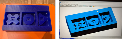
Milling wax
The wax we used was from Ferris.
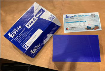
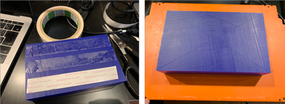
I taped the wax onto the platform of SRM-20.
I marked the center of the wax, and set the origin point of SRM-20 to there.
I used 1/8 inch endmill to do roughing and finishing.
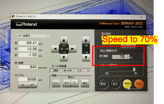
During milling, since the sound of milling was too strong, I changed the speed to 70% on Vpanel .
This is how it is like after roughing.
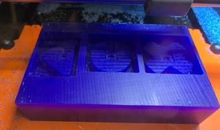
The 3D preview of Modela Player was very un-smooth so I was concerned. However, it turned out very smooth after the finishing! So I guess the graphic of 3D preview wasn’t reliable.
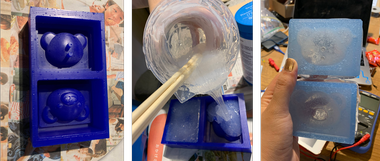
Molding mold
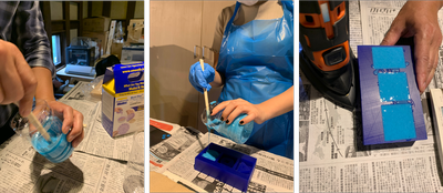
As safety measure, we were aprons, gloves, and goggles.
To make sure it doesn’t get too messy, we put newspaper on the table.
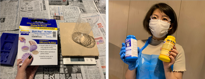
I used Mold Star 16 fast to make the mold.
According to the website:
Mold Star™ rubbers are easy to use platinum silicones which are mixed 1A:1B by volume (no weighing scale necessary). Mold Star™ silicones feature relatively low viscosities and vacuum degassing is not required for most applications. Mold Star™ 16 FAST is a fast material with a 6 minute pot life and 30 minute cure time.
It seems like it is 1A:1B by weight too, so I weighed part A and B with a ratio in weight of 1:1 (I used 70g of each), and put them into a cut clean plastic bottle.
I mixed it slowly within it’s pot life (6 minutes) making sure it doesn’t create many bubbles.
Then I poured the mixture into the mold with a chopstick guiding the stream, making sure the stream is thin to avoid bubbles.
I used a handy machine to shake the table where the mold it put to remove bubbles, and let it cure for 30 minutes.
These caution measures are all because bubbles would effect the finish. If the bubble happens to be on the surface, it would create unwanted craters.
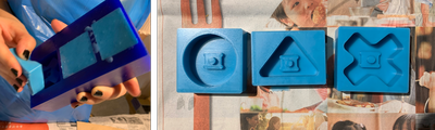
Then I removed it with force and got the silicon molds!
Casting
The group assignment page of FabLab Kamakura 2019 has a thorough introduction to all the casting materials in the inventory. I refered to it a lot.
Smooth Cast 300
I used Smooth Cast 300 to cast the button caps.
According to their homepage,
The Smooth-Cast® 300 Series of liquid plastics are ultra-low viscosity casting resins that yield castings that are bright white and virtually bubble free. Vacuum degassing is not necessary. They offer the convenience of a 1A:1B by volume or 100A:90B by weight mix ratio.
The pot life is 3 minutes, and cure time is 10 minutes.
I measured 10g of A and 9g of B, tried to mix it very well.
However, I wasn’t fast enough so the material hardened when I poured it into the mold…
So I prepared more and got the button caps!!
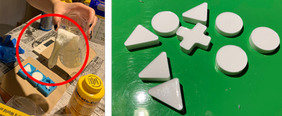
SORTA-clear 37
I wanted to make a food safe mold to cast chocolate, so I used SORTA-clear 37.
This is the homepage of SORTA-clear 37.
According to it’s page:
SORTA-Clear™ Series rubbers are premium water white translucent silicone rubbers (platinum catalyst) which cure at room temperature with negligible shrinkage. Sorta Clear 37 has Shore 37A hardness and features high tensile and tear strength. This product also offers the convenience of a 1A:1B by volume mix ratio.
SORTA Clear™ 37 silicone rubber is FOOD SAFE and can be used for culinary applications including casting chocolate and other confections.
I measured both 120g of part A and B, mixed thoroughly and poured into the mold.
I used the mold made by Toshiki Tsuchiyama because a bear is more suitable for chocolate.
Wow it is very hard to mix, and has so many bubbles inside…
I left it for a week since I had to leave the lab, and removed it then.
It was good, but it got the blue color of the machine wax, and the ear of the bear has holes because of the bubbles…
Maybe if I didn’t leave if for a week, it wouldn’t be so blue?
And according to the homepage, it is recommended to vacuum the material before curing to remove bubbles…
Maybe I will try casting chocolate with it someday. Someday…
After week15
-
I was surprised by how smooth the wax is milled by a 1/8 inch endmill. Apparently if your pattern has more details, you can consider using combining X, Y and countour for finishing.
-
Molding and casting is a very efficient solution when wanting to produce many same shapes.
File
- 3D model made with Fusion 360 .f3d file