17. Mechanical design, machine design
This week, students of FabLab Kamakura and FabLab Kannai came together to create Machine Orchestra in a Distant Society.
We each built our music machine so we can operate based on the note sent through MQTT.
The group page is here.
I made Elmo - the drunken conductor.
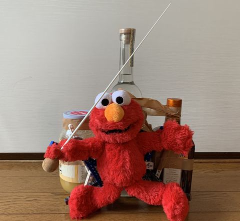
The idea is to make Elmo dancing to the rhythm.
Machine prototyping
I made the structure using LEGO parts like this. The structure is mainly consist of linkages.
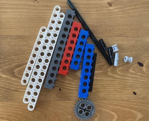
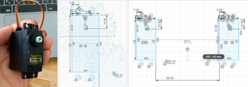
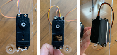
Servo motors - Tower Pro MG995 - were used to automize the movements.
I used one for the left arm and left foot, and one for the right arm and right leg.
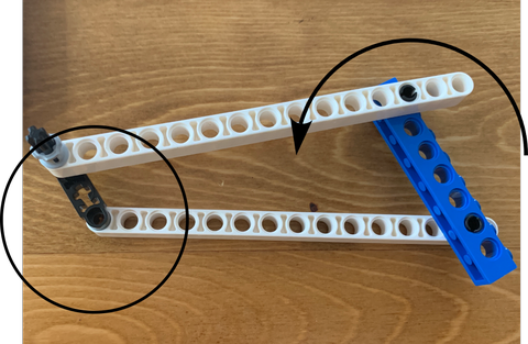
Linkages
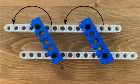
I made several structures to study four-bar mechanisms. And these are the 3 fundamental ones.
Parallelogram linkage
The 2 arms move in a parallel manner:
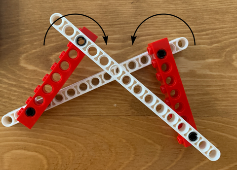
Crossing linkage
The 2 arms move in an opposite direction.
Crank rocker
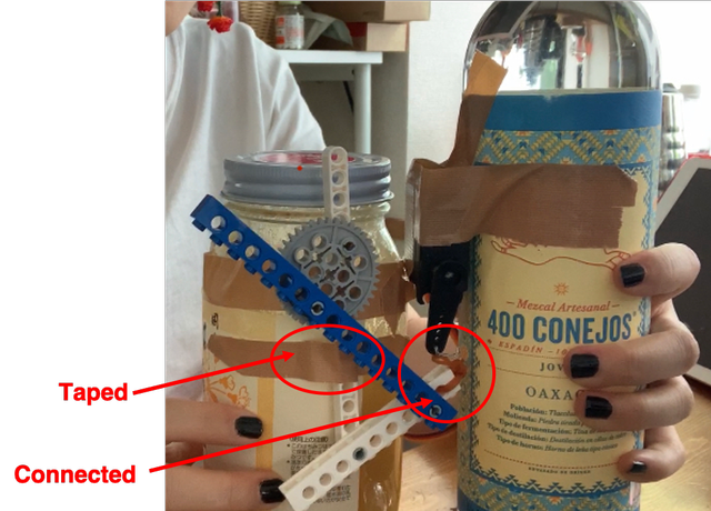
Connect to motor
Since it is hard to build the linkage when the structure is only supported by hand, I taped the structure and the motor onto a bottle.
To connect the motor to the structure, I used wire and rubber band.
The motor pulls the structure up.
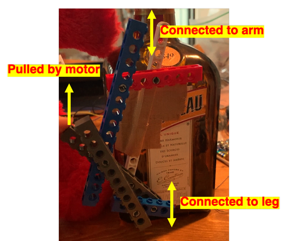
This is the right side of the body.
This diagrams shows the part that is pulled by motor, the part that is connected to move the arm and the leg.
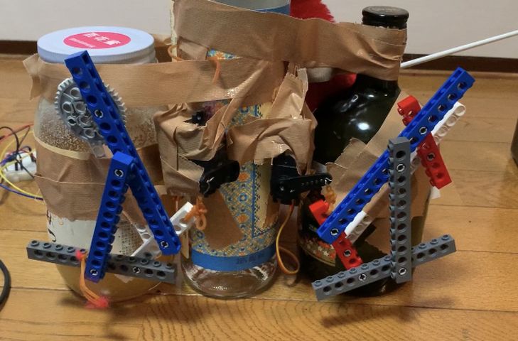
This is the whole body:
Programming
Connect to MQTT
The setup to connect to MQTT is probably on the group page.
Program the motor
At first, I installed a library called ESP32servo, and ran this code.
#include <ESP32Servo.h>

Servo myservo1;


int pos = 0;
int servoPin1 = 13;

int servoPin2 = 12;


void setup() {
    myservo1.setPeriodHertz(50);
    myservo1.attach(servoPin1, 500, 2400);

      myservo2.setPeriodHertz(50);
  myservo2.attach(servoPin2, 500, 2400);
}
void loop() {

        myservo1.write(10);
        myservo2.write(10);
        delay(1000);

        myservo1.write(120);
        myservo2.write(140);
        delay(1000);
}
It moved my servo motors individually.
However, it stopped working when incorporated into the program ran under MQTT.
I got to know that there are 2 timers in ESP32, and in this library, the timer interrupts that of Wifi communication.
So I found another library with which the author also used wifi communication to run servo motor.
I refered to this page, installed the library downloaded from there, and arranged my code according to the sample code.
And it moved under MQTT’s control!
I followed t5, and had the arm moving up and down every time I received 1 and 0.
(Wifi info and authorization keys are substituted with ***.)
#include <Servo_ESP32.h>

/*
 * Description:
 * Example for setting the minimal and maximal angle.
 */

static const int servo1Pin = 13;
static const int servo2Pin = 12;


Servo_ESP32 servo1;
Servo_ESP32 servo2;

/*
This is a sample template program for ESP32 connecting to
AWS IoT over MQTT to make distributed machine device for group
project of Machine design and mechanial design in
FabAcademy 2020 (students at Fablab Kamakura and Kannai).

As this code contains certification information, PLEASE
DO NOT UPLOAD THIS SOURCE CODE to ANY SHARABLE PLACE
DIRECTLY(including FabAcademy page). If you need to upload
this to sharable place, PLEASE MAKE SURE YOU DELETE
VALUES OF rootCA, certificate and privateKey CHARACTORS.

For preparation, please find PubSubClient.h in youf local
library and chhange #define MQTT_MAX_PACKET_SIZE 128 to 512.

For using this, please update as follows.
1) Set your ssid and password
2) Configure your topic (or for your use to publish/receive message)
3) Specify your topic name to subscribe in connectAWSIoT()
4) Write your logic on receiving message in mqttCallback()
5) Write your logic for publishing message in mqttLoop()  // <-optional
*/

#include <WiFiClientSecure.h>
#include <PubSubClient.h>
#include <ArduinoJson.h>

#include <ESPmDNS.h>


// 1) set your ssid and password ----------
char *ssid = "***";
char *password = "***";
// 1) end ---------------------------------

// AWS_IOT endpoint setting (fixed)
const char *endpoint = "a2toz7cb5zl4er-ats.iot.ap-northeast-1.amazonaws.com";
const int port = 8883;
//char deviceId[4]; // random device ID in 4 digit hexadecimal (max: ffff)
byte mac_addr[6];
char deviceId[20];

// 2) configure your topic (or for your use to connect to other people) -----
// Topic name needs to be format in "fa2020jp/topic[*]"
// Topic for publishing (if you do not need to publish, you do not need pubTopic.
char *pubTopic0 = "fa2020jp/topic0";

// Topic for subscribing
char *subTopic0 = "fa2020jp/topic0";

// 2) end -----------------------------------------------------------

const char* rootCA = "-----BEGIN CERTIFICATE-----\n" \
***
"-----END CERTIFICATE-----\n";

const char* certificate = "-----BEGIN CERTIFICATE-----\n" \
***
"-----END CERTIFICATE-----\n";

const char* privateKey = "-----BEGIN RSA PRIVATE KEY-----\n" \
***
"-----END RSA PRIVATE KEY-----\n";

WiFiClientSecure httpsClient;
PubSubClient mqttClient(httpsClient);


void setup() {
    Serial.begin(115200);

    // Start WiFi connection
    Serial.println("Connecting to ");
    Serial.print(ssid);
    WiFi.begin(ssid, password);

    // wait until WiFi connected
    while (WiFi.status() != WL_CONNECTED) {
        delay(500);
        Serial.print(".");
    }
    Serial.println("\nWifi Connected.");

    // Configure certification and MQTT Client
    httpsClient.setCACert(rootCA);
    httpsClient.setCertificate(certificate);
    httpsClient.setPrivateKey(privateKey);
    mqttClient.setServer(endpoint, port);
    mqttClient.setCallback(mqttCallback);

    // Set device Id from Mac Address
    WiFi.macAddress(mac_addr);
    sprintf(deviceId, "%02X:%02X:%02X:%02X:%02X:%02X", mac_addr[0], mac_addr[1], mac_addr[2], mac_addr[3], mac_addr[4], mac_addr[5]);

    connectAWSIoT();
    servo1.attach(servo1Pin);
     servo2.attach(servo2Pin);

servo1.write(10);
servo2.write(10);

}

void connectAWSIoT() {
    while (!mqttClient.connected()) {

        if (mqttClient.connect(deviceId)) {
            Serial.print("mqtt Connected - deviceId: ");
            Serial.println(deviceId);
            // QoS 0 is sending message only 1 time (the fastest)
            // QoS 1 is returning puback to publisher after send message successfully
            // QoS 2 is sending message only 1 time with validation (the slowest)
            // AWS IoT only allows QoS 0 or 1.
            int qos = 0;

            // 3) Specify your topic name to subscribe -----------
            mqttClient.subscribe(subTopic0, qos);
            // 3) end --------------------------------------------
            Serial.println("Subscribed.");
        } else {
            Serial.print("mqttClient.connect() Failed - deviceId:");
            Serial.println(deviceId);
            Serial.print("Error state=");
            Serial.println(mqttClient.state());
            // Wait every 5 seconds until connect to MQTT broker
            delay(5000);
        }
    }
}


int t4;
int t5;
int t6;

void mqttCallback(char* topic, byte* payload, unsigned int length) {
    DynamicJsonDocument doc(256);

    // Write serial monitor
    Serial.print("Received. topic=");
    Serial.println(topic);

    // deserialize
    DeserializationError error = deserializeJson(doc, payload);
    if (error) {
        Serial.print("deserializeJson() failed with code ");
        Serial.println(error.c_str());
        return;
    }

    // 4) Write your logic on received message -----------------

    // dump Json in readable format
    serializeJsonPretty(doc, Serial);
    Serial.println();
    // parse Json (retrieve int value from for each track)

    int seq = doc["seq"].as<int>();
    int interval = doc["interval"].as<int>();
    int overhead; // overhead for each beat (returned by pushSolenoids())

//    int t1 = doc["t1"].as<int>();
//    int t2 = doc["t2"].as<int>();
//    int t3 = doc["t3"].as<int>();
//     int t4 = doc["t4"].as<int>();
    int t5 = doc["t5"].as<int>();
//    int t6 = doc["t6"].as<int>();

    switch (t5) {
        case 0:
          servo1.write(10);
          servo2.write(10);
          delay(500);
         servo1.write(120);
         servo2.write(120);
          delay(500);


   // }
      break;
    //for(int posDegrees = 180; posDegrees >= 0; posDegrees--) {
       case 1:
        servo1.write(10);
          servo2.write(10);
          delay(500);
         servo1.write(120);
         servo2.write(120);
          delay(500);

      break;

    }

    // 4) end -------------------------------------------------
}


void mqttLoop() {
    if (!mqttClient.connected()) {
        connectAWSIoT();
    }
    mqttClient.loop();

    // 5) ----- Write your logic for publishing message from here -----
    // (If you are not pubishing anything, you can delete following code)

    // Publisher publishes folowing element
    // seq: sequence status (start from 1 when start sound)
    // count: count (start from 1 when start publisher process (on Node-RED in RaspPi)
    // t1: melody1 (in MIDI note name)
    // t2: melody2 (ex. harmony, in MIDI note name)
    // t3: code,  (in MIDI note name)
    // t4: rhythm1 (8 beat, front)       1, 0, 1, 0, 1, 0, 1, 0
    // t5: rhythm2 (8 beat, back)        0, 1, 0, 1, 0, 1, 0, 1
    // t6: rhythm3 (8 beat, variation)   1, 1, 0, 1, 0, 1, 1, 0
    // interval: interval in delay

//    mqttClient.disconnect();
    // 5) end---------------------------------------------------
}


void loop() {
   // server.handleClient();
  mqttLoop();
}
Trouble shooting
I had several troubles during the programming.
Breaking Barduino 2.0
I plugged and unplugged FTDI cable on Barduino 2.0 too many times and the pins fell off…
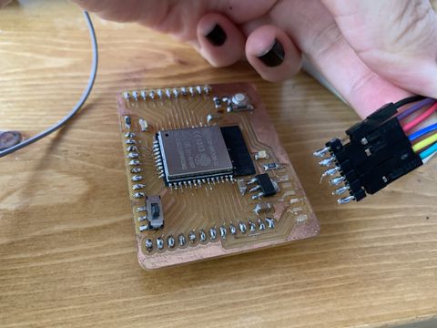
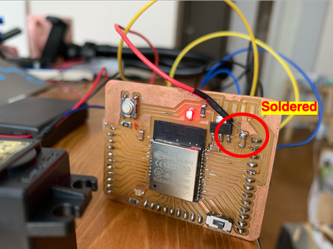
I found that there are pins for GND, Tx and Rx, so I decided to use those, and soldered a jumper wire to the spot that connects to VCC.
And it actually worked!! I felt very empowered…
Power supply issue
Since ESP32 only provides 3.3V while the motor requires voltage over 4.2V, I firstly tried to supply power from FTDI cable while running the program on ESP32.
However, the motor didn’t work accurately, probably due to power shortage.
So I connected it to a battery box with 4.5V.
It worked, but it ran out of battery really fast.
So I decided to hack a USB cable.
I cut off the head, revealed the VCC and GND cable, and soldered jumper wires onto them.
And it supplied 5V voltage!!
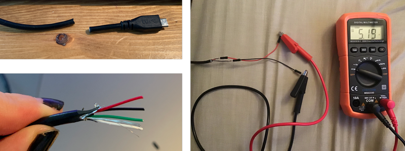
I plugged it to a charger that supplies 2.0A and it successfully powered 2 servo motors. (Yamamoto san told me to use charger that supplies >1A.)
Prototype outcome
Elmo’s arms and legs are connected to the parts with rubber band.
The batton is also attached to the hand using a rubber band.
(Actual) Machine building
When I started to have lab access again, I decided to build a proper machine instead of taping Elmo onto bottles for stability and reproducibility.
While still using 2 servo motors to control each side of the Elmo body, I decided to use a gear system instead of a linkage system.
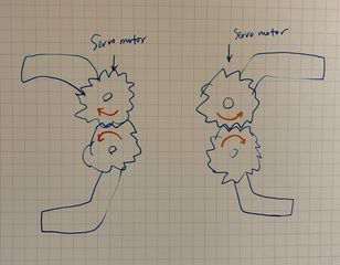
On each side there will be 2 gears. 1 gear is connected to the servo motor, and the other gear would have opposite movement when the 1st gear moves.
This is the sketch of the design as a whole.
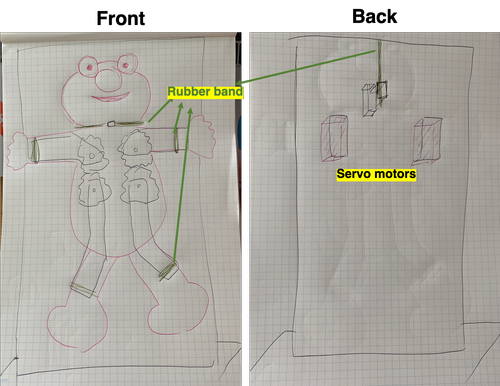
Acrylic will be laser cut to create the gears, the parts (sketched with black lines) that support Elmo’s arms and legs, the frame to support servo motors.
Elmo’s head, arms, and legs are tied to the parts with rubber bands (sketched with green lines).
Design
I used Fusion360 to do the design work.
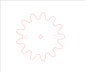
Gear
I refered to this video on how to make gears and simulate the movement.
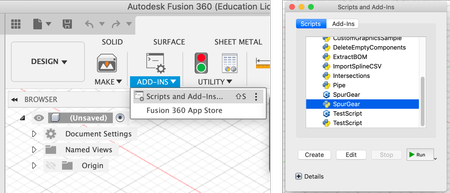
To make a gear, I opened Scripts and Add-Ins in Tools > ADD-INS.
In there I chose SpurGear ran with Python. (It seems that either Python or C++ would work the same.)
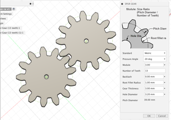
I made 2 same gears with:
-
Pressure angle 20
-
Module 3.00
-
Number of teeth 13
-
Gear thickness 3mm
-
Hole diameter 3.2mm
Once these parameters are set, it tells you that the pitch diameter would be 39mm.
And I manually dragged to place the 2 gears so their pitch circle touches each other.
Then I sketched circles that align with the hole of each gear, extruded them to make cylindars as axis.
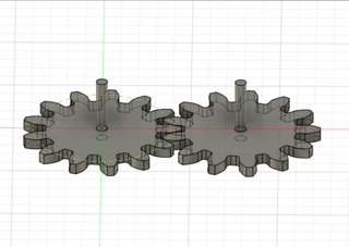
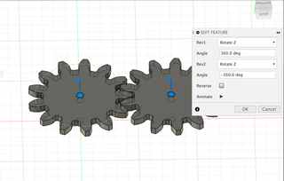
To simulate the movement of gear spinning, I added joint (ASSEMBLE > joints) with the hole of the gear, and the circular surface of the cylindar as faces.
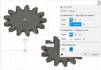
After setting joints on both gears, I used motion link (ASSEMBLE > motion links) to link the movements of the 2 gears.
I selected the joints as rev 1 and rev 2.
I exported the sketch of gears as DXF.
But when I opened it in Inkscape…
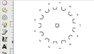
… :(
Inkscape couldn’t sketch the curves… It seems that it works with Illustrator well, but not Inkscape.
So I made vector file for gears using this webpage based Involute Spur Gear Builder.
I refered to the parameters I set on Fusion 360.
Here are the parameters I changed:
-
Pressure Angle 20
-
Wheel 1 tooth count 13
-
Wheel 1 hole diameter 3.2
-
Show Wheel 1 only
Circular pitch is calculated automatically based on the parameter input.
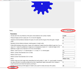
After hitting “Update”, I hit “generate DXF” to export the DXF file.
So I was able to open it in Inkscape.
I added 2 holes with diameter of 3.2mm so I can screw the gear onto the servo motor.
I saved it as .svg file and cut 4 gears.
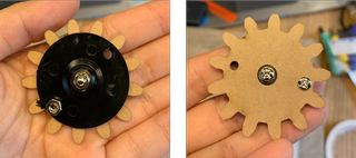
The servo motor comes with accessories including a plate that fits onto the servo. I opened 2 holes on the plate with hand drill to align with the holes on the gear, and screwed the gear onto it.
I put a screw in the middle to screw the gear onto the axis of the motor too.
Body support
Then I designed the parts to support Elmo body.
I used Insert > Insert SVG to import the gear’s sketch into Fusion 360.
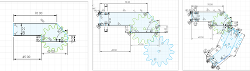
I sketched the support for arm.
Then I duplicated the gear and manually positioned it next to the first gear.
And I sketched the leg support.
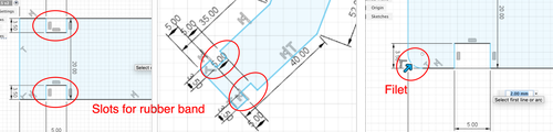
Frame
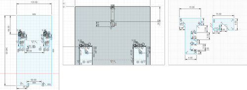
Then I made an acrylic frame to support the motors and Elmo.
I sketched a rectangle shape to fit the motor in, and 4 circular holes to screw the motor onto the acrylic.
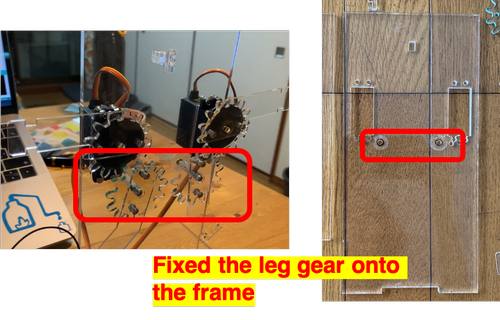
I also added a hole to fix the leg gear on.
I copied and pasted for the other side of the body.
I sketched the outline of the frame, added a slot to put in key-shaped parts to hold Elmo’s head.
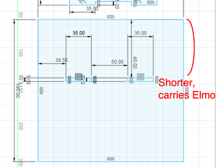
Bottom
I sketched the bottom to fit the frame onto it.
I didn’t put the slots in the middle, but one side shorter than the other.
The shorter side will carry Elmo, since the longer side is needed to balance out the weight of Elmo
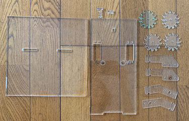
Production
I used 3mm acrylic for gears and arms&legs support parts, 5mm acrylic for frame and bottom.
I used TROTEC Speedy 100 to cut.
Assembly
I used M3 screws of different lengths for assembly.
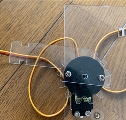
I put the servo motor into the rectangular slot, and screwed it onto the acrylic frame.
I screwed the arm support part, gear, motor top together and put it onto the servo motor’s axis.
For the leg’s gear, I used a spacer and 3 nuts to create space between the gear and the frame.
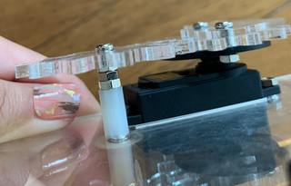
I also learned about double nuts method (reference).
Screwing 2 nuts together fixes the position of the nuts to prevent self loosening.
Actually in the previous design, I didn’t make the hole on the acrylic frame to fix the leg gear.
I was using a linkage to connect arm & leg gear, however the leg gear moved not as I expected.
That’s why I decided to add a hole onto the frame so I can screw the leg gear onto it and fix the movement.
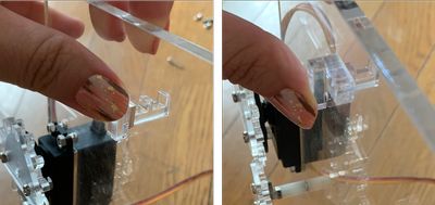
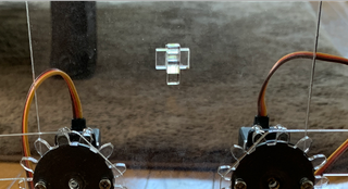
And I put the little key part in as the head holder.
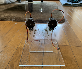
This is how it looks like when assembled!
This is how I put the rubber bands onto Elmo’s head, arms and legs.
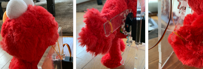
Tadaaa!
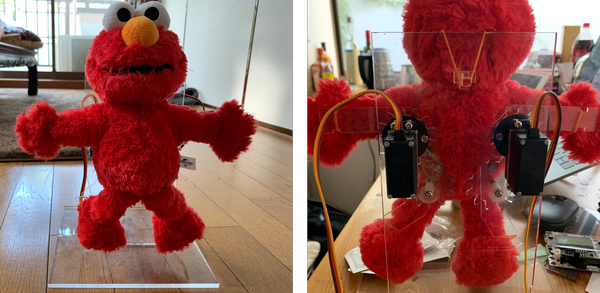
Program
As before, I connected both servo motors onto ESP32’s pin 12 and 13.
I wrote this program onto ESP32 while adjusting the angles.
#include <Servo_ESP32.h>

static const int servo1Pin = 12;
static const int servo2Pin = 13;

Servo_ESP32 servo1;
Servo_ESP32 servo2;


void setup(){
  Serial.begin(9600);
}

void loop(){
        servo1.write(50);
          servo2.write(100);
          delay(1000);
         servo1.write(100);
         servo2.write(50);
          delay(2000);


}
It moved a lot more stable than before! Not a drunken conductor anymore :P
After week17
I learned a lot about the basics of machines, including linkages, gears, and the usage of screws. Also when prototyping, fixing some parts using tape could be very helpful.
Great thanks to Homma-san for all the help regarding network, Oguri-san for all the advices on machine building, Yamamoto-san for the advices on electronics as always.