Sewn circuit (Other project)
Exploring the potential of sewn circuit for workshops with children.
My plan is to use ATtiny44 to control the LEDs sewn on textile.
Prototype with Breadboard
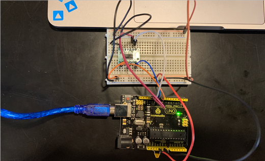
To start, I prototyped the circuit with a breadboard.
Solder ATtiny44
To connect ATtiny44 to a breadboard, I soldered ATtiny44 onto a board with these feet.
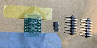
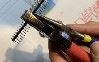
To get the exact number of feet I wanted, I used 2 plyers to break the connections.
I firstly soldered ATtiny44 onto the board with it taped onto a wooden board as the picture above. I applied flux onto the surface and soldered.
To solder the feet, I inserted the feet into a breadboard and put the soldered ATtiny44 onto it for stability.
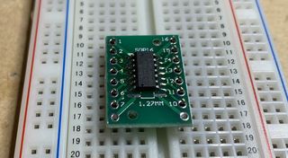
I heated the upper tip of feet and then applied solder onto them. Apparently if you heat too much, the plastic of the feet would melt so be careful of that.
Set up Arduino UNO as ISP
First, I connected Keyestudio UNO to the computer.
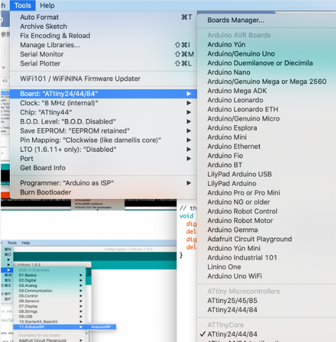
In Arduino IDE, I opened the program to write ISP through:
File > Examples > 11.Arduino ISP > Arduino ISP.
To set up the connections,
Tools > Board > Arduino/Genuine Uno
Tools > Port > (the one on the bottom)
I ran the program to make Keyestudio UNO an ISP.
Program ATtiny44 with Arduino UNO
I followed this tutorial to program ATtiny44 with Arduino UNO.
I connected the circuit following the instrcutions:
- Connect a 10 uF capacitor between “Reset” and the upper “Ground” pins on the Arduino Uno board. The instruction mentioned “The stripe of the capacitor with the negative sign (“-”) goes to the Arduino “Ground” pin. This prevents the Arduino Uno from resetting and ensures that the Arduino IDE talks to the ArduinoISP (and not the bootloader) during the upload of the sketches to the ATtiny.” but I didn’t check that when I connected and it worked fine.
- Connect the ATtiny84/44 Pin 1 (with the little dot) to the 5 volt breadboard rail.
- Connect the ATtiny84/44 Pin 14 to ground.
- RESET: Connect the ATtiny84/44 Pin 4 (Reset) to Arduino Pin 10.
- MOSI: Connect the ATtiny84/44 Pin 7 to Arduino Pin 11.
- MISO: Connect the ATtiny84/44 Pin 8 to Arduino Pin 12.
- CLOCK: Connect the ATtiny84/44 Pin 9 to Arduino Pin 13.
- Connect the ground and 5v from the Arduino to the breadboard.
And I connected an LED to pin 7 and to ground via a current limit resistor. Pin 6 on the ATtiny44, for example, is actually Arduino digital pin 7 (see pinout diagram at the beginning of the post).
This diagram shows which pins on Arduino UNO correspond to which pins on ATtiny44.
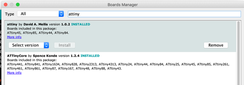
In order to set ATtiny44 as board, I installed ATtiny support following this tutorial.
I went to Boards manager (Tools > Board > Boards manager), searched for “attiny” and installed the one by David A. Mellis.
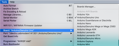
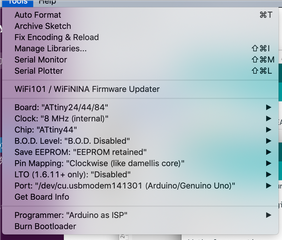
Set up the board, ISP, etc. in Tools.
I chose ATtiny24/44/84 under ATTinyCore as the board.
Set Port to the correct one, chose “Arduino as ISP” as the programmer, and made sure other settings are like the image below.
Then I ran this program:
/*
  Blink (modified slightly for ATTiny84/44 ICs
  Turns on an LED on for one second, then off for one second, repeatedly.

  This example code is in the public domain.
 */

// ATTIny84 / 44 does not have Pin 13, so we use pin 7 instead.
// A current limiting resistor should be connected in line with the LED.
int led = 7;

// the setup routine runs once when you press reset:
void setup() {
  // initialize the digital pin as an output.
  pinMode(led, OUTPUT);
}

// the loop routine runs over and over again forever:
void loop() {
  digitalWrite(led, HIGH);   // turn the LED on (HIGH is the voltage level)
  delay(200);               // wait for a second
  digitalWrite(led, LOW);    // turn the LED off by making the voltage LOW
  delay(200);               // wait for a second
}
And it blinked!