8. Embedded programming
Assignments
- Group assignment
- compare the performance and development workflows for other architectures
- Individual Assignments
- read a microcontroller data sheet
- program your board to do something, with as many different programming languages and programming environments as possible
Group Assignment
See the FabLab Kamakura site page.
Individual Assignments
Program with Arduino IDE
Several weeks ago, as an early-stage prototype for my sewn circuit project, I programmed an ATtiny44 using Arduino IDE with the FabTinyISP I made.
I read the data sheet of ATTiny44 to figure out the functions of each pins.
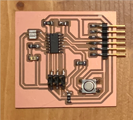
The circled 6 pins are used to connect to the 6 pins of FabTinyISP.

And I used PA7 pin for LED, and connected a 499 Ohm resistor between LED and GND.

To get power supply for ATTiny44, I connected VCC and GND via FTDI cable to my laptop.

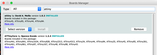
To install the ATTiny44 as a board option in Arduino IDE, I went to Boards manager (Tools > Board > Boards manager), searched for “attiny” and installed the one by David A. Mellis.
Set up the board, ISP, etc. in Tools.
I chose ATtiny24/44/84 under ATTinyCore as the board.
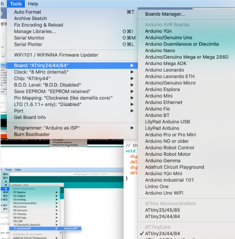
I set Port to the correct one, chose “USBtinyISP” as the programmer.
And ran this program:
int led = 7;

// the setup routine runs once when you press reset:
void setup() {
  // initialize the digital pin as an output.
  pinMode(led, OUTPUT);
}

// the loop routine runs over and over again forever:
void loop() {
  digitalWrite(led, HIGH);   // turn the LED on (HIGH is the voltage level)
  delay(100);               // wait for a second
  digitalWrite(led, LOW);    // turn the LED off by making the voltage LOW
  delay(100);               // wait for a second
}
And here it goes!
Program with C language
Then I tried to program the hello board I made in Electronics design week:
Code
I wanted to make the LED blinking to the alphabet thats being input based on the alphabet’s binary code. My strategy was to combine the echo.hello code from FabAcademy class with an LED blink code by Kae Nagano from FabAcademy2019.
To understand where to modify on the echo.hello code, I received a helpful recitation from Kae-san.
She broke the code down into 6 sections with different fuctions.

“#include” is to include the necessary header file in AVR-GCC. The tip is to only include the necessary ones since the memory storage is limited. ATTiny44 only has a memory of 4KB.
“#define” is where the names of the functions to be used in the program are listed. It is always written as function_name(variable)(processing_details).
“#get_char” is to transfer alphabet into binary digits.
“#put_char” is to transfer binary digits into alphabet.
“#put_strings” is to output strings - the “hello…” expression that shows up everytime when the board echos.
“#main” is the main loop indicating what to do with all the functions.
(Above are my personal interpretations based on the recitation so it can be partially incorrect.)
I added the following definitions for LEDs to the “#define” section.
#define led_port PORTA
#define led_pins PINA
#define led_pin_out (1 << PA7)
#define led_direction DDRA
I should have disabled the unused “#define”s but I couldn’t since I was too overwhelmed… Luckily they didn’t do anything bad.
I kept the “#get_char” section since I need it to transfer alphabet into binary code.
In “#put_char”, I changed:
 if bit_test(txchar,0)
      set(*port,pin);
   else
      clear(*port,pin);
   bit_delay();
into
if bit_test(txchar,i) {
      led_port |= led_pin_out;
      _delay_ms(100);  }
    else {
      //clear(*port,pin);
      led_port &= (~led_pin_out);           // led off
      _delay_ms(100);    }
And I changed the whole process of checking each digit into a loop by adding for (int i=0; i<8; i++) {} outside of the code above.
Instead of serial, I wanted to have the output expressed as the lighting pattern of LED, so in the “#main” section, I disabled
set(serial_port, serial_pin_out);
output(serial_direction, serial_pin_out);
and added these instead:
led_port |= led_pin_out;            // set led port
led_direction |= led_pin_out;    // set led port direction
I added led_port &= 0x7F; so the program starts with the LED off.
I tried to do it by changing 1 to 0 in #define serial_pin_out (1 << PA1) but it didn’t work.
“#put_strings” and “#put_char” is to output characters and strings. But since I only needed to output signals through LED not strings or characters, I disabled all the lines related to #put_char and #put_strings. (You can disable the code by putting “//” in front of the line, or putting “/” and “/” to a paragraph.)
Then I copied the echo.hello.c.make file to the same folder as I saved my .c file, changed the name into the same one as the .c file, and changed PROJECT into the .c file’s name inside the .c.make file.
Write program to ATTiny44
In terminal, I ran $ make -f ledstep.c.make to create .c.make file.
I recieved message like this:
ledstep.c:131:4: error: 'else' without a previous 'if'
  131 |    else
      |    ^~~~
ledstep.c: In function 'put_string':
ledstep.c:195:7: warning: implicit declaration of function 'put_char'; did you mean 'get_char'? [-Wimplicit-function-declaration]
  195 |       put_char(port, pin, str[index]);
      |       ^~~~~~~~
      |       get_char
ledstep.c: In function 'main':
ledstep.c:206:15: warning: variable 'index' set but not used [-Wunused-but-set-variable]
  206 |    static int index;
      |               ^~~~~
ledstep.c:205:16: warning: unused variable 'buffer' [-Wunused-variable]
  205 |    static char buffer[max_buffer] = {0};
      |                ^~~~~~
At top level:
ledstep.c:205:16: warning: 'buffer' defined but not used [-Wunused-variable]
For the error, I definitely had “if” in front of “else”…
I tried many things, but what worked was to delete the space and lines with “//” in front. And the error disappeared!
Warnings seem to be ok.
Then I ran these 2 lines.
$ sudo make -f ledstep.c.make program-usbtiny-fuses
$ sudo make -f ledstep.c.make program-usbtiny
AAAAND…
Test with oscilloscope
I used oscilloscope to test if the input and output is correct.
I tested with letter a which is expressed as 01100001.
This is the input wave.

With starting bit 0 and ending bit 1, and that you need to read backward, you can see that the 8 digits in between represents 01100001 which is exactly the one for “a”. The second half of the wave represents “NL(new line)”.
Since the LED is an output to the serial, it wouldn’t show anything if I put the clip onto Tx. Instead, I was adviced to probe on somewhere near the resistor.

I enlarged the time unit to see the output, and saw this wave.

Reading backwards, it’s exactly 01100001. It means that it is outputing correctly!!
Read data sheet
Besides identifying the pins, I also had some other findings through reading the datasheet.
In features,
“2K/4K/8K bytes” indicts the programmable memory of ATTiny24/44/84.
“EEPROM” represents data that is processed at once.
“SCRAM” represents the speed for actual processing.
“Endurance” represents the number of times this chip can be written in a life time.

For each pin, PORTA represents all the PA pins while PORTB represents all the PB pins.
We also learned that “OC0A”, “OC0B”, etc. represent registers. The datasheet mentions a lot about clock, but I didn’t quite understand… I’m hoping to understand it through projects in the future.
I also learned a lot about clock and PWM in Output devices week.
You can see my documentation here.
After week08
I had traumatizing experience with the C language back in college. Therefore I was concerned about this week, but thanks to the intructors support, it turned out to be not so bad! I mean it is still difficult and sometimes frustrating. Kae-san helped me program step by step. But after I finished and looked back, I got a better understanding about the structure and gained more confidence!
Files
Program with Arduino IDE
- attinyblink.ino file