8. Embedded Programming#
ESP8266 (Oka)#
I played around with ESP8266 for this week’s group assignment.

Arduino IDE#
Firstly I programmed on it from Arduino IDE.
board setting like following images.

add esp8266 thing on board manager.

install manager for esp8266.

the name of board showed up on the list.

set like this

Tried the Niel’s sample program

worked!
MicroPython (installing)#
Secondly, I tried MicroPython on ESP8266.
MicroPython is a compiler and also a runtime that runs on the micro-controller hardware.

there was documents about MicroPython to install.
But youtube instruction by Null Byte was easier for me to install and execute MicroPython for me. I tried the way indicated on it.
download Firmware for ESP8266 from micropython.org

Find the serial port for connecting with ESP8266
1 | |
You can find all the serial port your laptop has
Then, remove USB cable and command it again
The port disappeared is the one you are using for ESP8266

/dev/cu.usbserial-DN05J6TR
was my USB port to use.
install esptool.py on my laptop
1 | |
erased the flash on ESP8266
1 | |
deployed the new firmware on ESP8266
1 | |

MicroPython was installed on ESP8266
MicroPython (REPL)#
then, started to connect with ESP8266 via serial connection by screen command and it started to run python on it
1 | |
MicroPython worked on ESP8266 as interactive inline style which is called REPL stands for Read Evaluate Print Loop. it works as an interactive prompt for ESP8266.

and also possible to control ESP8266 as a micro controller.
End connecting with the command
1 | |
MicroPython (transfering a python file and executing it)#
Then, I tried to put .py file on ESP8266 and run it
install adafruit-ampy which can transfer files to the microcontroller board via serial communication and run MicroPython on it.
1 | |
create program file(blink.py) with python.
1 2 3 4 5 6 7 8 9 10 | |
command for Put & Run
1 | |
1 | |
worked!
there are two ways to run python program on ESP8266.
one is to execute command as a interactive prompt style. and the other is transfer the prepared program file to ESP8266. then compile and run it.
Tsuchiyama#
microbit#
“microbit” is a small computer board for education developed primarily by the British Broadcasting Corporation (BBC).
- Front Features
・5 columns of red LED in the center (total of 25)
・1 button (total of 2) on each side (tact switch) - At the bottom
・Three I/O rings (0~2)
・External power supply ring (3V/GND)
・A 20-pin edge connector between the rings allows for more advanced features such as serial communication over I2C and SPI.

- Behind Features
・32-bit ARM Cotex-M0 based processor
・Triaxial acceleration sensor
・Geomagnetic sensor (compass)

MakeCode Editor#
It can be programmed using color-coded blocks like Scratch and it can be operated from a web browser.
Programing#
I tried programming to light up the “♡” using MakeCode Editor.
I extracted the program “show icon” from “Basic” in the command tab and put it in the “fover” program.
As a result, a “♡” appears in the preview on the left.
Eventually, we also used a program with a small “♡” mark to write something that moved “♡.”

Save the downloaded hex file to a USB-connected microbit.

↓
Python#
It can program with a Python text code that is specific to microbit, and it can be operated from a web browser.
Programing#
I’ve tried programming that uses Python code to make the word “hello world” shine and scroll.
I couldn’t create the hex file with Safari browser, so I created it with Google Chrome browser.

Save the downloaded hex file to a USB-connected microbit.
↓
Links to Files and Code#
Oguri#
Scratch GPIO on Raspberry Pi#
As an example of Embedded Programming, I tried blinking LED by Scratch GPIO on Raspberry Pi ( OS ; Raspbian ).
reference links
Scratch, wiki
https://en.wikipedia.org/wiki/Scratch_(programming_language)
Scratch, web version
https://scratch.mit.edu/projects/editor/?tutorial=getStarted
Scratch GPIO
https://www.raspberrypi.org/documentation/usage/gpio/scratch2/README.md
https://deviceplus.jp/hobby/raspberrypi_entry_010/
when I started Scratch, a message, “Now, the remote sensor access is available” appeared. This means “GPIO function is activated”.
| “Now, the remote sensor access is available” | pin10 (GPIO15) -> LED LED -> resistor -> GND |
|---|---|
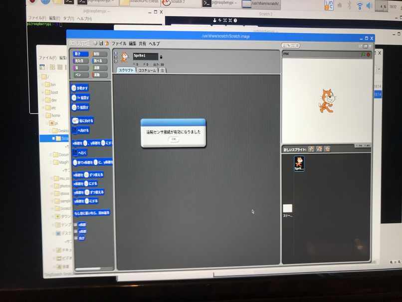 |
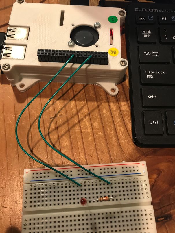 |
| click -> send “pin10on” -> 1sec delay -> send “pin10off” -> 1sec delay |
test |
|---|---|
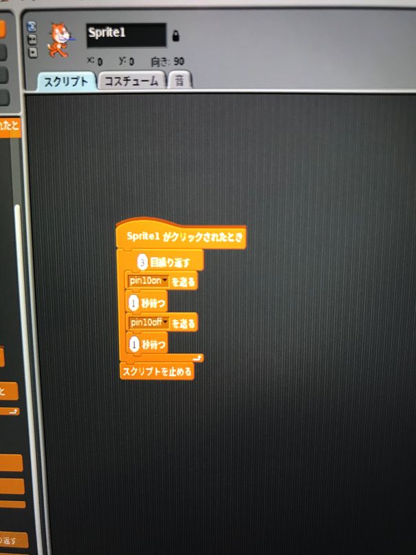 |
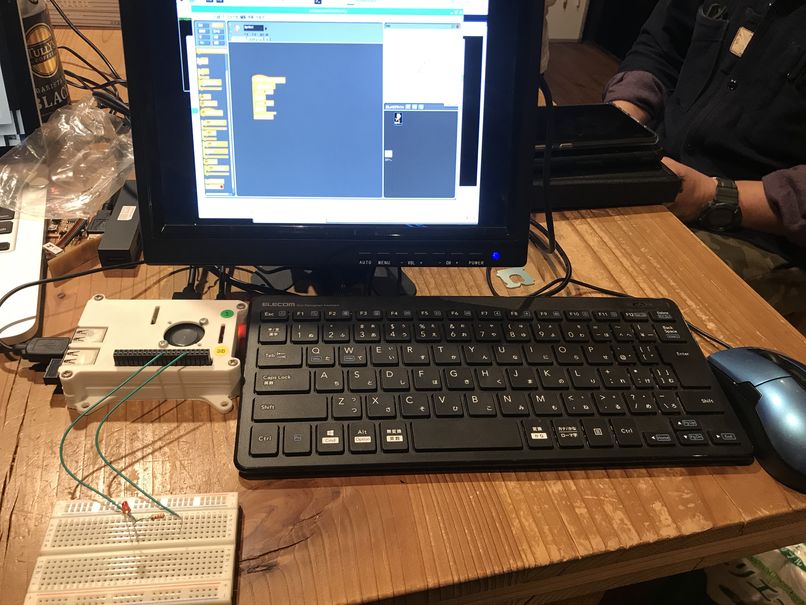 |
It worked fine.
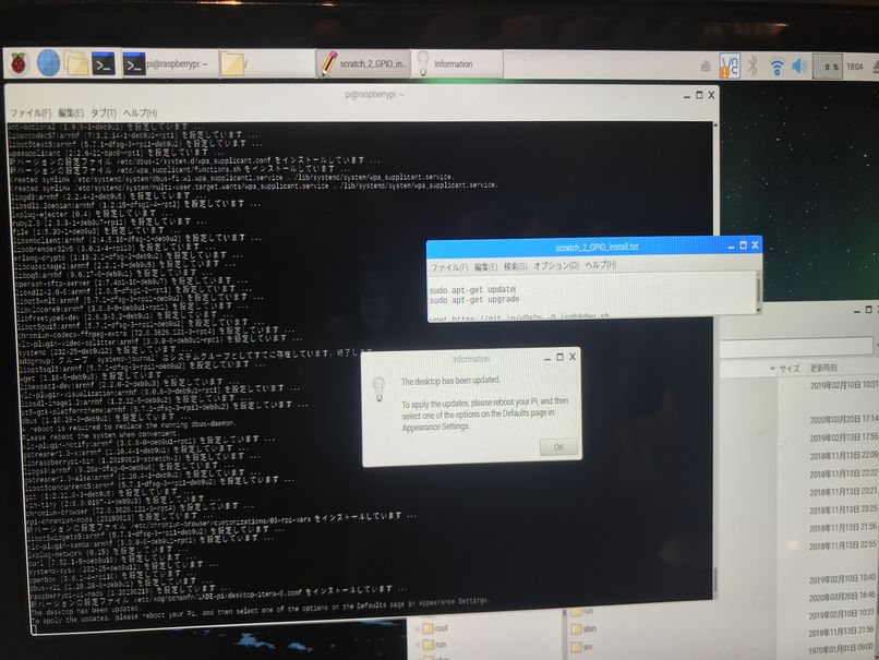
Before performing the above, I updated Scratch2, then installed GPIO.
https://will-be.fun/scratch2-gpio
Yume#
I tried to program ESP-WROOM-32 with Arduino IDE. The board I used was ESP32 COREBOARD V2.

I set up the environment to write program onto ESP32 following this tutorial.
To add ESP32 to “Board” in Arduino IDE, I opened Arduino > Preferences, and added https://dl.espressif.com/dl/package_esp32_index.json to Additional Boards Managers URLs. I used “,” to separate the URLs.
Then I opened Tool > Board > Board Manager, searched for “esp32” and installed “esp by Espressif Systems”.

In Tools, I selected “ESP32 Dev Module”, and “AVRISP-mkll” as the programmer.
At this point, there is no serial port selectable in Tool > Port. I installed the drive from this page.
After installing, the serial port showed up as SLAB_USBtoUART.

I also tried the following code to initial the setup in this tutorial. Although I don’t know if it was necessary since afterwards I heard that other people succeeded without doing this procesure.
1 2 3 4 5 | |
To program LED blinks, at first I followed the same tutorial and used this code,
1 2 3 4 5 6 7 8 9 10 | |
It returned me some code with these lines in the end. These are supposed to be for success but nothing blinked…
1 2 | |
It seemed that there are 2 buttons on the board, EN(RST) and BOOT.
To change the board to writing mode, I pressed EN and BOOT, releasing EN first, then BOOT.
I tried to write the code again, but nothing happeded…
Then I observed the board again, finding that unlike the tutorial, the board I have does not have a 2nd LED except for the LED that indicates power!
So I connected the board with an LED and a resistor via a breadboard following this tutorial.
I connected the LED to IO4 and ground, resistor to GND pin and ground.

I put the following code into Arduino IDE, compiled and ran.
(The previous code I used for LED blinks would have worked too.)
1 2 3 4 5 6 7 8 9 10 | |
The yellow LED blinked!
Kimura#
Raspbreey Pi#
scratch#

I tried to blink LED with raspbreey pi using scratch / python language.
Open Scratch, Edit → Start GPIO Server

Set gpio17pin

raspbreey pi pin arrangement
In scratch, 17
In python, it seems to use 11 (green circle number).

This completes the program.

When you click on the green flag, the LED starts blinking every second.
python#
I wrote the python code in the default text of raspbreey pi and saved it as “blink.py”.

1 2 3 4 5 6 7 8 9 10 | |
Enter the following command in the terminal and the LED will start blinking.
1 | |
Yanome#
For group assignment, I tried using micro:bit and controlling its LED with some directions.
First, I introduced the spec. of micro:bit.
You can see the overview of the feature of micro:bit;
Key Features
You can see the features of micro:bit here.
- Application Processor - nRF51
The nRF51 application processor is where user programs run. A single, complete application including user code, runtime code and bluetooth stack is loaded and run directly from on chip flash memory.
• 2.4 GHz transceiver
• ARM® Cortex™-M0 32 bit processor
• 275 μA/MHz running from flash memory
• 150 μA/MHz running from RAM
• Serial Wire Debug (SWD)
• Memory
• 256 kB or 128 kB embedded flash program memory
• 16 kB or 32 kB RAM
-
Display
The display is a 5x5 array of LEDs. It is connected to the micro:bit as a 3x9 matrix. -
Motion Sensor
The micro:bit has a combined accelerometer and magnetometer chip that provides 3-axis sensing and magnetic field strength sensing.
It also includes some on board gesture detection (such as fall detection) in hardware, and additional gesture sensing (e.g. logo-up, logo-down, shake) via software algorithms.
Tasks for Programming
You can control micro:bit by using the combination of blocks and also writing Javascript codes. This time, I chose blocks controlling.
I set the tasks as below;
-
Task1: As pushing button A, LED turns on as number “1”.
-
Task2: As pushing button B, LED turns on as number “2”.
-
Task3: As shaking micro:bit, LED turns on as character “X”.
How to control micro:bit using blocks
Build the blocks with the direction, complete the tasks.
Tip
Simulate the actual behavior
You can simulate the actual behavior by the icon of micro:bit on the screen.

And then, clicked download to download .hex file.
Connected micro:bit to my PC and sent .hex file into micro:bit through Finder. So .hex file was read and varnished (but can be read properly).
Tried working micro:bit!
Using block was sooo easy to control. Only 5 minutes it took to set all the tasks although this is my first time to use micro:bit.