4. Electronics production
Assignments
-
Group assignment
Characterize the design rules for your PCB production process -
Individual Assignments
Make an in-circuit programmer by milling the PCB,
check if you can program it,
then optionally try other PCB processes.
Group Assignment
Check out the Kamakura site page here
Individual Assignment
This week I made these 3 boards: a failed FabTinyISP, a successful FabTinyISP, and a FabISP.

FabTinyISP
To make FabTinyISP, I followed this tutorial.
Creating path data
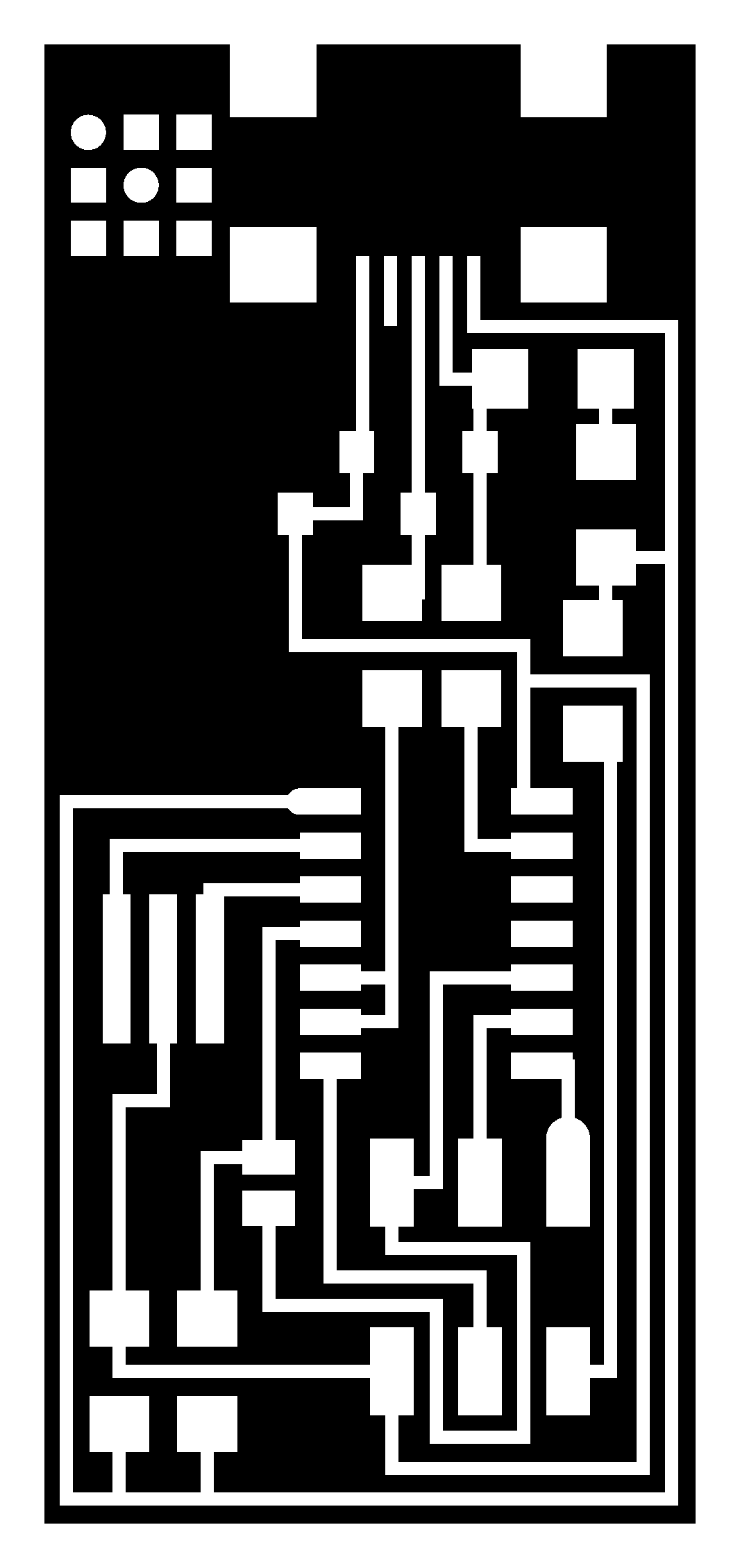
I used MODS to create .rml for cutting from the existing png for traces and cut.

I opened the website of MODS. Right click on the logo > programs > open server program > Roland SRM-20 PCB png. This page is activated.

I disconnected the “WebSocket” module (you can also delete it) since we won’t be using internet connection.
Right click any blank space near the “image threshold” module, module > open server module > file save, connect input file on the save file module with output image of “image threshold” module. This enables automatic save after calculating the image.
The reason to disconnected the “WebSocket” module is because:
MODS was designed to operate on a lab full of networked machines. However, FabLab Kamakura’s machines are not connected to the internet nor are they networked internally (yet)… hence cannot use websockets to send milling instructions to the SRM20…
At the moment, the extra work to save the file to USB, move it to the PC attached to the SRM20 is needed for milling.
Usually we start with traces with 1/64 inch mill, and then cut the outline with 1/32 inch mill, since the board will get unstable after cutting the outlines.
To cut traces, open FabTinyISP’s trace png in “read png” module, choose “mill traces (1/64)” in “set PCB defaults” module, confirm the parameters in “Roland MDX-20 milling machine”. Note that origin of x and y is by default set to 10mm, so I changed it to 0 to actually cut.
Press “calculate” in “mill raster 2D” module, it generates the toolpath, and automatical downloads the .rml file.


The same workes for all other pngs too.
One fascinating fact is that the paths generated in the .rml file are actully 3 dimensional.

Milling
To change the mill, I loosened the collet, took the former mill out, put the new one in, and tightened the collet.
Then I opened Vpanel to set the XYZ origin points.
When the lid of SRM-20 is closed, the mill moves automatically to the pre-set origin point.
To set the origin point to the marked center point, I opened VPanel for SRM-20, moved X/Y to set origin point to the marked center point.
To set Z origin point, set the mill close to the cut surface, loosen the collet and lower the mill manually so it hits the surface. Then tighten the collet.
The machine remembers the set origin point, resets when the machine is restarted.

I loaded the .rml file and cut.

After cutting, I dropped some disolvent and took the part out.
Soldering
I collected these parts for stuffing.

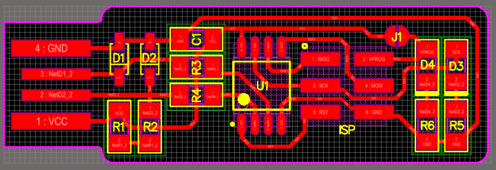
I soldered based on this board pattern.

The polarities of LED and Zener Diode matter in these 2 boards.
For LEDs, according to the datasheet, the banded side is cathode.

For Zener Diode, according to the datasheet, the banded side is cathode.

I found the serial number of each through FabLab Kamakura’s inventory, searched for the data sheets of each, and figured out the polarities in the data sheets.
I applied flux onto the board, tape the PCB onto a bigger board for stability, and solder from inside to ouside, lowerest to the highest component.
However, during my first attempt soldering a FabTinyISP, after soldering everything onto the board, I burned the mini USB header to connect with USB port…

Through this, I learned some important rules and tips when soldering:
- Start with the mini USB header. So I won’t waste all my effort if I break it in the end.
- Use 250-270 degree C and thinner solder for small parts, 320-350 degree C and thicker solder for larger parts such as the end.
- Apply solder to the same place for 3 times maximum.
- Heat the board and the part enough before inserting solder.
And I got this rather smoothly and shiningly soldered boards.

Vise was used to connect 6 head pin with 6 cables to make a connector between ISP and microcontroller.

Programming the ISP
I used ATAVRISP2 to program FabTinyISP.
I installed Crosspack from it’s webpage, and Firmware.
I extracted the zip file of firmware, in my terminal cd into the source code directory, and ran make. I confirmed there is a fts_firmware.hex new file created in the folder.
I connected AVRISP2 to FabTinyISP, typed in make flash, …
$ make flash
avrdude -p attiny45 -c usbtiny -P usb -e \
        -U flash:w:fts_firmware.hex
avrdude: Error: Could not find USBtiny device (0x1781/0xc9f)

avrdude done.  Thank you.

make: *** [flash] Error 1
To trouble shoot, I first checked if FabTinyISP is physically well connected to the USB port.
In my case, some soldered parts were too high than the others. This might cause the lower ones lacking of contact to the port. I used a file to make the higher ones lower.
Also, I cut off the unecessary copper piece on the edge of the end with ultra-sonar cutter.

… same error.
I tried to create a path for CrossPack
$ export PATH=$PATH:/usr/local/CrossPack-AVR-20131216/bin
I didn’t fully understand how to do it, but I understood if it is not done, it wouldn’t refer the program to the designated directory.
… same error.
I unistalled Crosspack with $ sudo /usr/local/CrossPack-AVR/uninstall, and installed avr-gcc and avrdude through homebrew with comand brew avrgcc and brew avrdude instead.
Before installing:
$ brew list
gdbm        openssl@1.1 python@3.8  sqlite
mkdocs      python      readline    xz
after installing avrgcc
After installing:
$ brew list
avr-binutils    isl     libusb      python
avr-gcc     libelf      libusb-compat   python@3.8
avrdude     libftdi0    mkdocs      readline
gdbm        libhid      mpfr        sqlite
gmp     libmpc      openssl@1.1 xz
… same error.
I typed in $ echo $PATH and $ export -p to get rid of the existing path.
… still same error.
THEN I RECOGNISED…
I didn’t define the programmer properly in make file.
I used avrisp2 to program FabTinyISP, so I needed to change PROGRAMMER ?= usbtiny into PROGRAMMER ?= avrisp2.
I connected the board, avrisp2 blinks yellow and FabTinyISP blinks red.

Ran make flash, ran make rstdisbl, and now my FabTinyISP is a programmer!
I disconnected J1 using soldering machine, plugged it onto my computer, and I discovered it on my system settings!

If you got the same error, you can confirm these questions to trouble shoot
- Is the ISP board physically well connected to the USB port?
- Is the ISP board connected to USB 2.0 port?
USB port on laptops are usually for USB3.0. A transferer is needed to connect both. - Are the parts correctly connected?
- Is avr-gcc and avrdude properly installed?
- Is path made for CrossPack?
- Is the programmer in make file correctly set?
FabISP
I heard that we are going to use the ISP for many assignments from now on, and FabTinyISP might be fragile, so I decided to make a FabISP as well.
I followed this tutorial and the documentation of Kae Nagano from 2019, Kamakura.
(The traces png for FabISP I used from the documentation is different from the one in tutorial. Crystal was replaced by resonator.)

Creating path data
I used MODS as well to create path data.
Milling
The same process as FabTinyISP. After changing to the appropriate mill, and setting XYZ origin point using Vpanel, I loaded the .rml file and cut.
After cutting, I dropped some disolvent and took the part out.
This time, some small unecessary parts remained and I used ultra-sonar knife to take them off. These parts might cause bridges, and when they fall off unexpectedly they can cause short circuit.

Soldering
I soldered based on this board pattern.

I collected these parts for stuffing.

And I soldered following the rules and tips I learned before.
Turned out to be pretty nice :)

“Smoke Test”
I plugged the FabISP into your computer via the mini USB cable.
I didn’t get an error message from your computer that the board is drawing too much power and that the computer is shutting down the USB port, so the test succeeded.
Programming the ISP
The process is similar as FabTinyISP.
I skipped the installing avr-gcc and avrdude process since I did it already.
I downloaded and unzipped its firmware.
I ran make clean, make hex, make fuse, make program, and I discovered it on my system reference!

I removed my two 0ohm resistors, and booooom! I got my FabISP programmer too!
Programming a board using the ISPs I made
I chose to program a board made by instructor Jun-san when he was attending FabAcademy 2018’s week 9. His documentation is here.
I borrowed his board, connected it to the laptop for power, and to my ISP for signal.

I downloaded his code for blinking listed in the end of the page. There are blink.c and blink.c.make files in there.
On terminal, cd to the folder where the .c and .c.make files are, and used these 3 command lines to run the program.
$ make -f blink.c.make
$ sudo make -f blink.c.make program-usbtiny-fuses
$ sudo make -f blink.c.make program-usbtiny
To verify that I was able to rewrite the program, I change the code a bit.
vi blink.c to open the code on terminal, i to insert/make changes.
This is the code.
#include <avr/io.h>
#include <util/delay.h>
#define F_CPU 2500000

int main() {

    DDRB = 0b00000100;

    while(1) {
        PORTB = 0b00000100;
        _delay_ms(1000);
        PORTB = 0b00000000;
        _delay_ms(1000);
    }

    return 0;
}
With FabTinyISP, I changed the delay time both from 1000 to 100.
Esc to quit editing, :wq to save and quit. Then ran the 3 lines above again.
And… It blinked very fast! This confirmed that FabTinyISP is able program!
With FabISP, I connected it in a same manner, changed the delay time in the code both from 100 to 1000.
It blinked every second now so this confirmed that FabISP is able program too.
I also learned that to embed local video, I need to write this line in HTML. And in HTML, the directory is 1 level different from markdown. If it is ../ in markdown, it is ../../ in HTML.
This is the code.
<video width="500"  controls>
  <source src="../../images/week04/FabTinyISPblink.mp4" type="video/mp4">
</video>
After week04
- I got more familiar with soldering, and got to understand (although not entirely) about how chips inside ISP and boards communicate each other. There are still a lot of things I don’t understand, such as what fuses are. I would love to actively explore it also when the programming week comes.
- I was very frustrated during the debugging process, but in the end I think I learned a lot from it, and it is a great learning experience after all.