
This work is licensed under a Creative Commons Attribution-NonCommercial-ShareAlike 4.0 International License
Week 8: Embedded Programming
Mar 23, 2021Summary
This week's assignments
- Group assignment:
- Compare the performance and development workflows for different microcontroller families ✔
- Document your work (in a group or individually) ✔
- Individual assignment:
- Read the datasheet for the microcontroller you are programming and document what you learned from reading a microcontroller datasheet ✔
- Program the board you have made to do something, with as many different programming languages and programming environments as possible:
- Program your board ✔
- Describe the programming process/es you used ✔
- Include your source code ✔
- Include a short "hero video" of your board ✔
Resources Used
- Software: Arduino IDE
- Hardware: Arduino, Raspberry Pi, hello.t412.echo
Skills Gained
- Basic Arduino programming
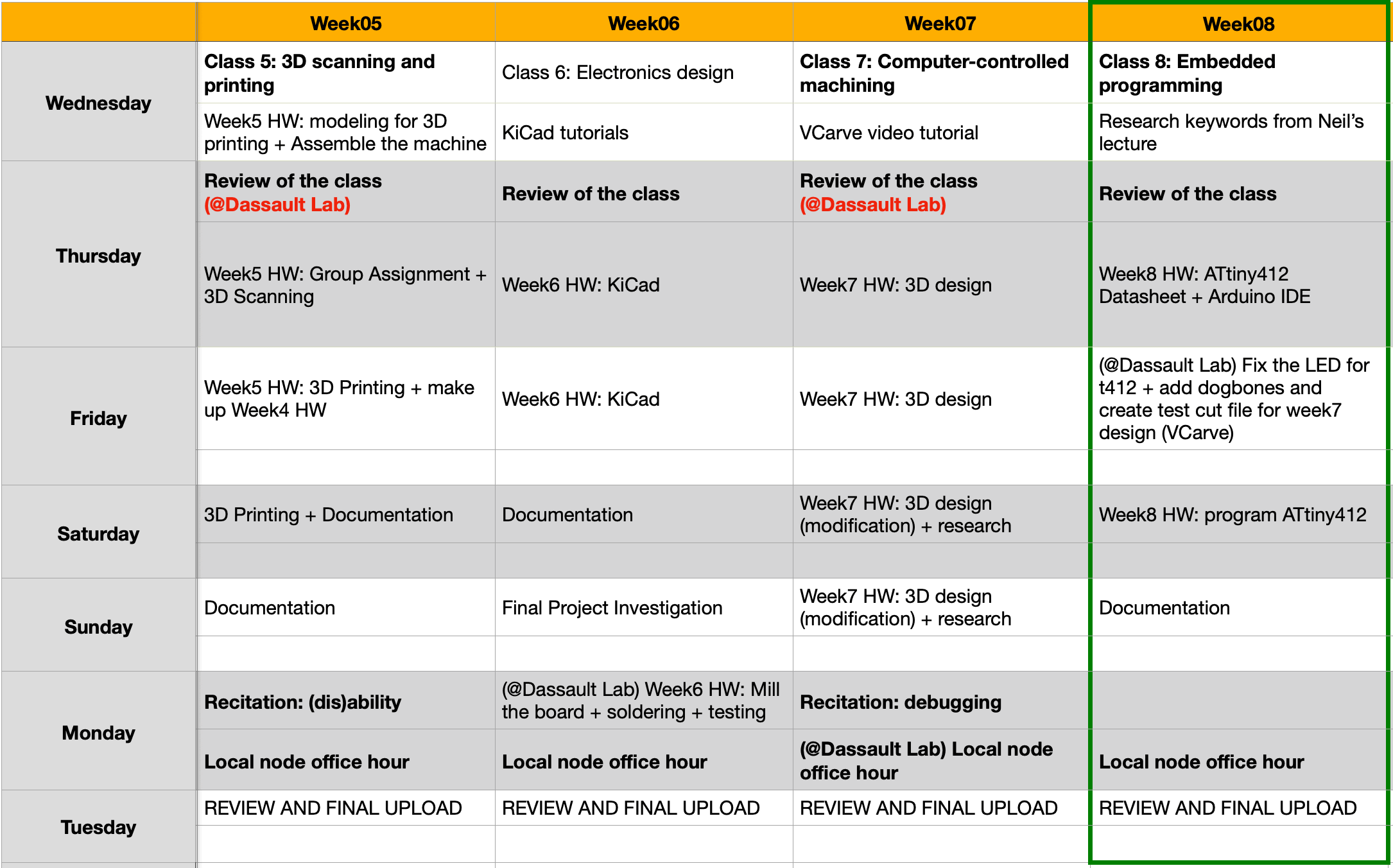
My Weekly Schedule
Group Assignment
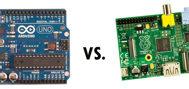
The group assignment this week was to compare the performance and development workflows for different microcontroller families. For this exercise, I have chosen to compare an ELEGOO UNO R3 board and a Raspberry Pi 3B. The microcontroller that the ELEGOO UNO R3 board had was ATmega328, which was within the AVR microcontroller family. (The ATtiny412 was also in the AVR microcontroller family.) The Raspberry Pi board is more complicated than the Arduino board, and it not just a microcontroller, rather it is like a mini computer with a Linux operating system.
ELEGOO (Arduino Clone) UNO R3
Here is some information for the board:
- Board: ELEGOO UNO R3
- Microcontroller: ATmega328
- Microcontroller Family: AVR
- Interface: 14 digital I/O interfaces
- Entrances: 6 analog
- Chip: 16 mHz crystal oscillator
- USB: USB connection
- Connector: ICSP header
- EEPROM: 1 KB
- SRAM: 2 KB
- Flash memory: 32 KB
- Cycle: 16 MHz
To begin, I followed TopTechBoy's Arduino tutorials and used some built-in Arduino examples to learn the basics. After learning how Arduino works, I started to create a basic LEDs blink pattern sketch on Arduino. The Arduino programming language is a simplified C/C++ language.
pre-setup area - define the global variables and load libries
setup area - where the tasks are only run once (i.e. setting as input or output for the pins)
loop - where the codes will be run repeatly and it is a place for the main codes
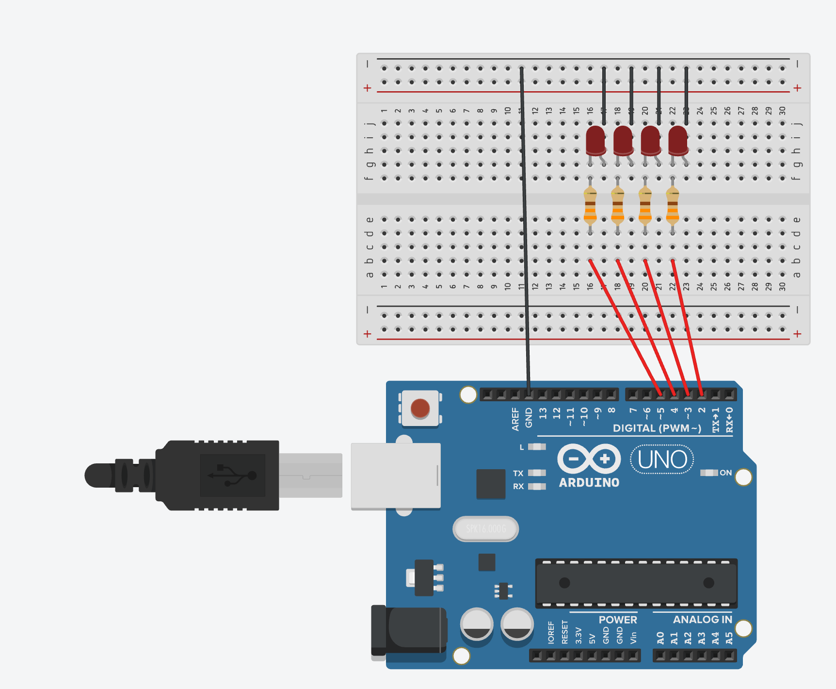
Bill of material:
- Board: ELEGOO UNO R3
- Wires: red jumper wires x 4 ; black jumper wires x 4
- LEDs: red LEDs x 4
- Resistors: 330Ω x 4
I used TinkerCAD Circuit to simulate the board, and here is how it looked:
In Arduino IDE, under the Tools tab, I set the following:
- Board: Arduino UNO
- Port: (the USB port that connected to my ELEGOO UNO R3 board)

And here is a short video of the blinking LEDs:
Raspberry Pi 3 Model B
Here is some information for the board:
- Processor: 700 MHz ARM 11 family
- Chip: Broadcom BCM2835
- Graphic: Broadcom VideoCore IV
- Random access memory (RAM): 1256 MB RAM
- USB: 2x USB 2.0
- Output: HDMI 1.4
- Audio: 3.5mm line out
- Drive: SD, MMC, SDIO card reader
- Network: 100 Mbit / s Ethernet
- Power supply: 700 mA
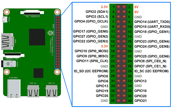
Similarly to learning Arduino, I followed Paul (TopTechBoy)'s Raspberry Pi series to learn the basics. From this documentation, I learned that GPIO was what set Raspberry Pi apart from the ELEGOO UNO R3 board that I experimented with previously. GPIO stands for general-purpose input/ouput, and it was the row of 40-pin header along the edge of the board. Any of these pins can be used as an input or output pin and can be used in a wide range of purposes.
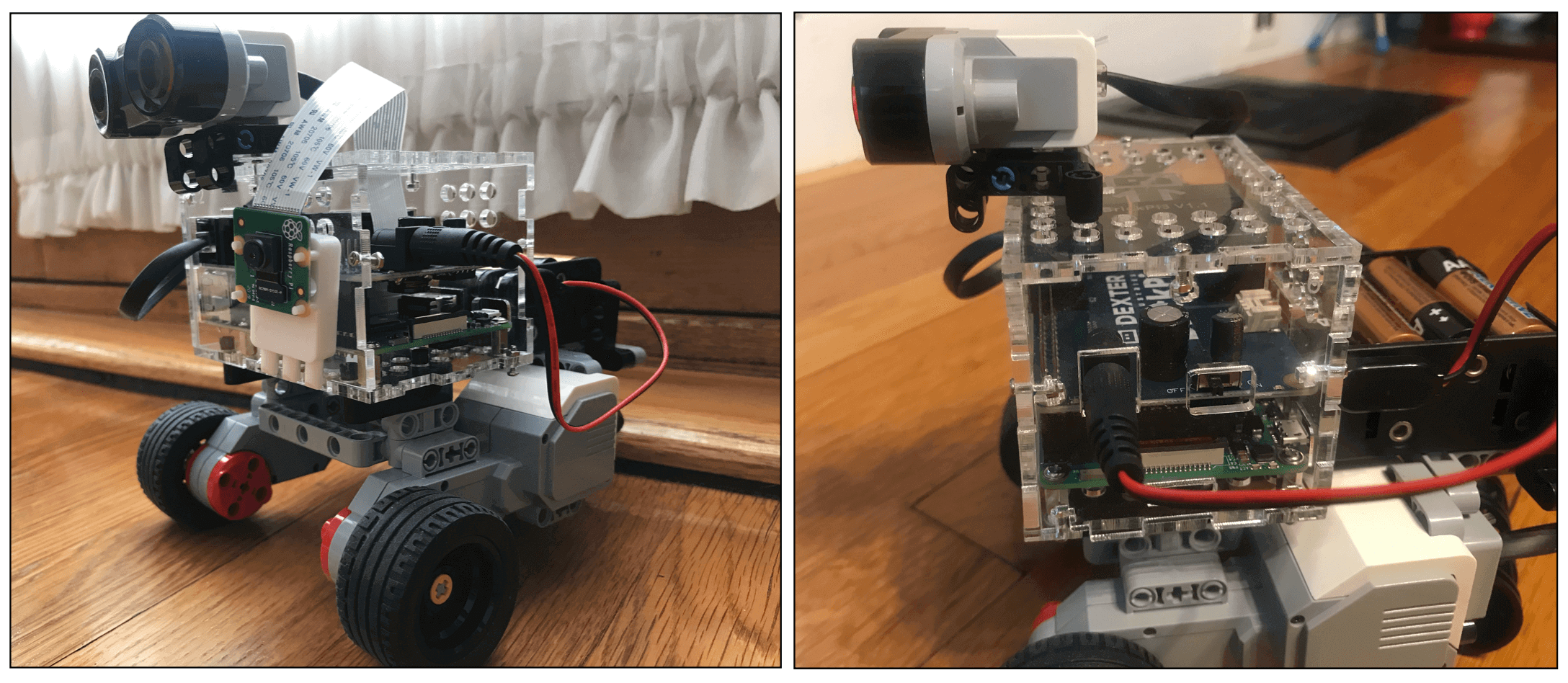
Here is a Lego EV3 / BrickPi robot that I have worked on with my classmates at school last year. Usually, a Lego EV3 is controlled by its proprietary "EV3 Brick" but that has many limitations when it comes to programming. In our robot, the BrickPi connected to the row of the GPIO pins in the RaspberryPi and that allowed my classmates and me to program the Lego robot in a Python environment.
Individual Assignment
Microcontroller
In order to understand the basic concepts for this week, I needed to do some more researching online after the Global Lecture on Wednesday, and I found these two websites (1 and 2) explain the concept very clearly. Here are some key information:
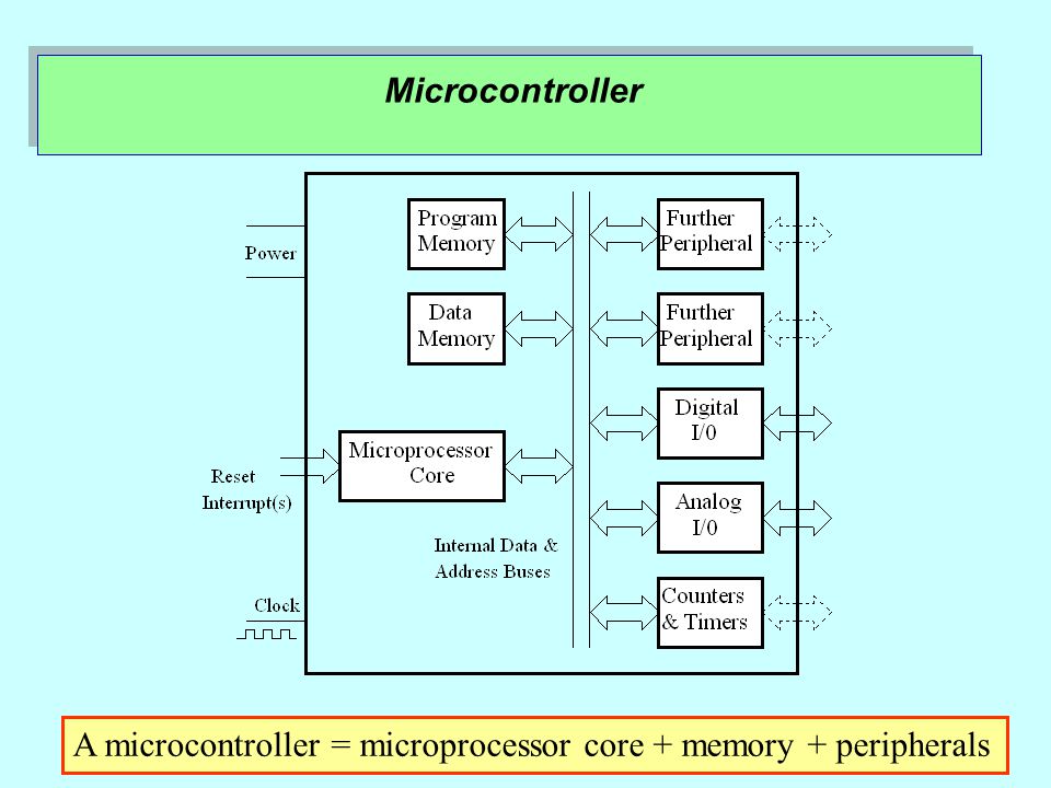
Hardware: a microcontroller is made up of 2 major parts, the microprocessor, and its peripherals. Basically, a microprocessor is made up of integrated circuits (IC) and its role is for executing our code. Peripherals are devices that help the microprocessor to accomplish a given job. The way the peripherals and the microprocessor of a microcontroller are arranged is called architecture.
Software: An IDE, or Integrated Development Environment, is a software that allows the programmers to write software into a single application. An IDE can be served as a text editor, debugger, and a complier for code. Oftentimes, programming language in the IDEs are written in C or C++ (i.e. Arduino IDE); the codes that we put into the IDE can be saved as a simple .hex file, or a C file (.ino), or Python.
Datasheet: ATtiny412 and SAMD11C14
One of the assignments this week was to read the datasheet, for this task I used this tutorial to learn how to read a datasheet first. During the Electronics Production week, I milled and soldered a SAMD11C14 UART/UPDI programmer, which was created by Quentin; and during the Electronics Design week, I used KiCad to create a blinky board using an ATtiny412 microcontroller. The ATtiny412 blinky board was based on Neil's design. Although I had worked on those assignments, I didn't know what these microcontrollers were capable of doing and what their differences were. This week, I was able to grasp some basic knowledge on them from the datasheet. Let's take a look!
Datasheet: ATtiny412
This is how the ATtiny 412 was named:
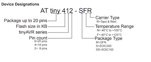
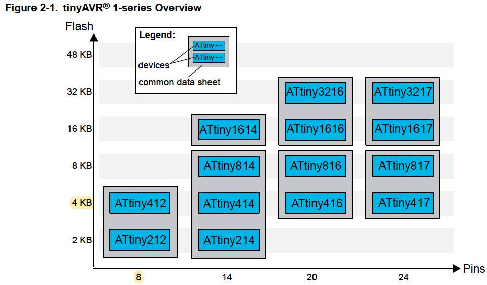
ATtiny412 (datasheet) is an 8-bit microcontroller within the AVR 1-series family, which worked for the newer computers according to our instructors. The AVR ISP family (i.e. ATtiny44 or ATtin45) didn't work very well for the newer computer USBS.
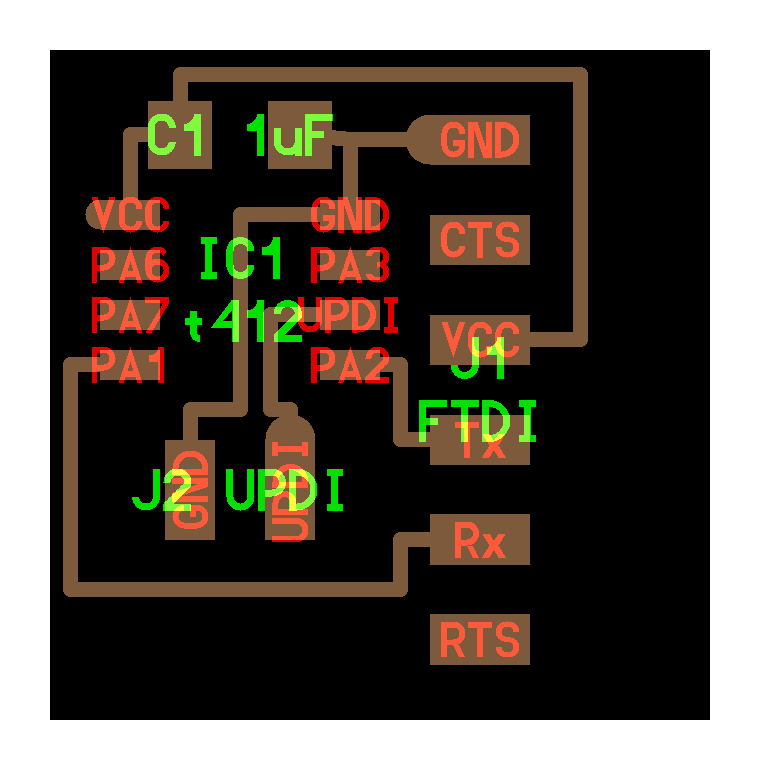
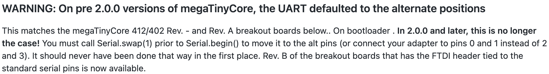
One of the pins (pin 6 in the ATtin7412 microcontroller) is connected to an UPDI (Unified Program and Debug Interface), which was used for transmitting (TX) and receiving (RX) serial information. In image 2 below, the UPDI can be identified as one of the legs in the 1x2 header; the other leg of the 1x2 header was connected to the Ground (GND).
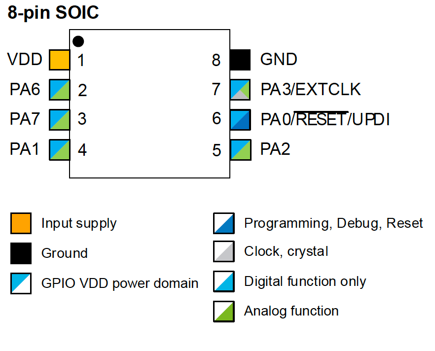
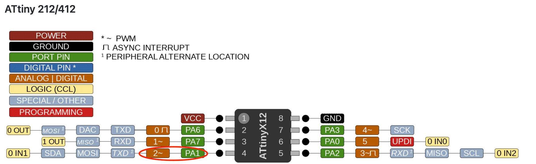
Here is the pinout for the ATtiny412 microcontroller. The VDD and GND are strictly reserved. The pinout was espeically helpful when I was soldering the real component because I needed to orient it in the correct way.
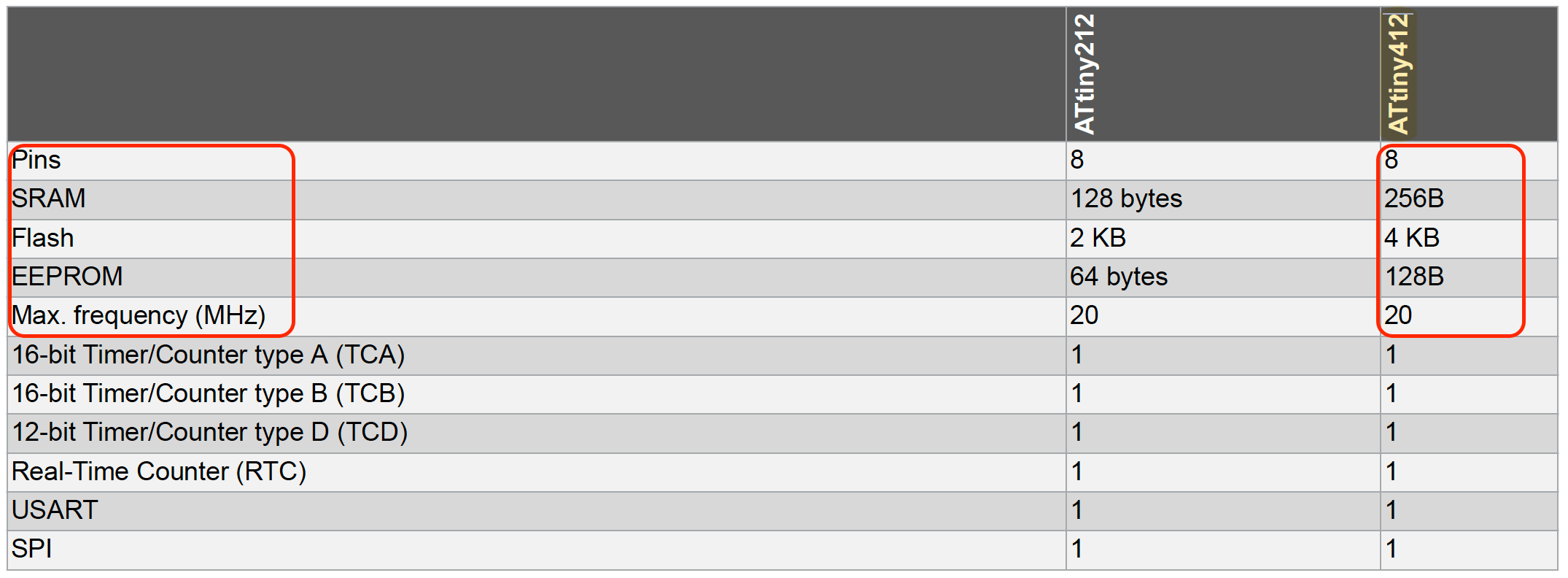
Here is the peripheral information for the microcontroller. Once again, I needed to look up for information on the different terms, and here is what I learned from the Arduino Foundations page:
- Flash memory: this is the program space where the sketch (code) is stored.
- SRAM (static random access memory): this is where the sketch creates / changes variables when it run.
- EEPROM: this is the memory space that programmers can use to store long-term information.
- USART (Universal Synchronous/Asynchronous Receiver/Transmitter): this offers synchronous program-to-program communication through the serial port.
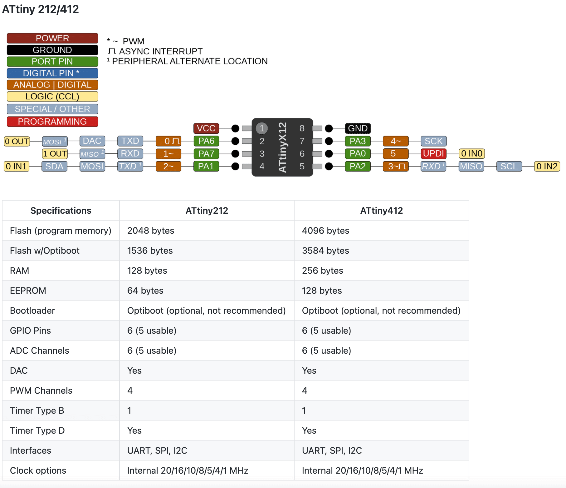
The Port Function table gave more details about what can the pins achieve. In addition to a clearer label of each pin, this table also included the pin numbers that could be used in the Arduino IDE. During the Electronics Design week, I learned to locate the default pins and the alternative pins in ATtiny412 from this information.
Datasheet: SAMD11C14
During the Electronics Production week, our instructors encouraged us to mill and solder the SAMD11C14 UART/UPDI programmer by Quentin as the board was very compact in size, and multifunctional. After learning mre about the SAMD microcontrollers from this video tutorial by Nicholas and Quentin, I became more appreciative with what our instructors asked us to do for the Electronics Production week. The datasheet for the SAMD11C14 microcontroller can be found here. Here is some of the key information:
This is how the SAMD11C14 was named:

The SAMD11C14 microcontroller is within the SAMD microcontroller family, it is much more powerful than AVR, and is capable of running at high speed, i.e. the SAMD11 devices operate at a maximum frequency of 48MHz, whereas the ATtiny412 only at 20MHz. That being said, the SAMD11 device allows for executing complex information faster (i.e. 1-cycle). Also, the SAMD1114 microcontroller has 16KB flash while the ATtiny412 has only 4KB. Another good thing about the SAMD11 device is that, it does not require the USB-to-Serial translator required once it becomes a programmer.

This GitHub page shared a wealth of information on the SAMD11C14 microcontroller. I also learned from the former Fab Academy students' sites, and found Adrián's visual representation of the pins very helpful.
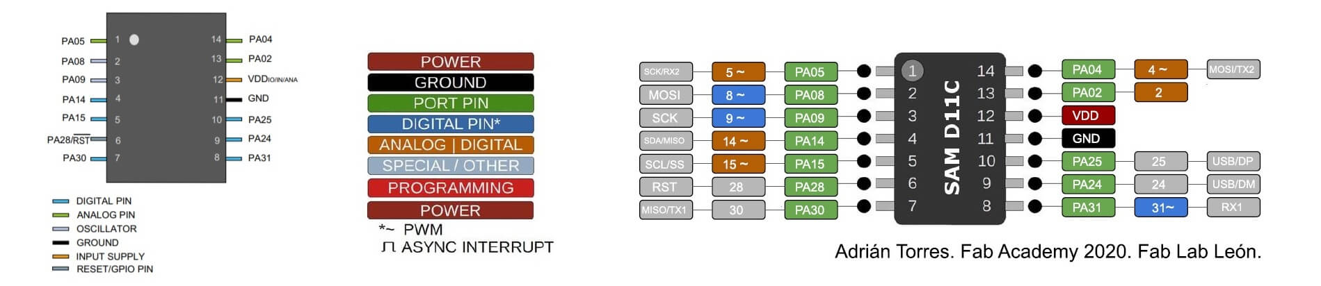
I also leanrned some pins are digital only, and some are analog, but can be used also as digital pins. This information would become helpful in the weeks to come. The datasheets are the instruction manuals for these devices, and there are a vast of information from them. It took a long time to scroll through all the pages but it was totally worth it.
Programming my ATtiny412 Board
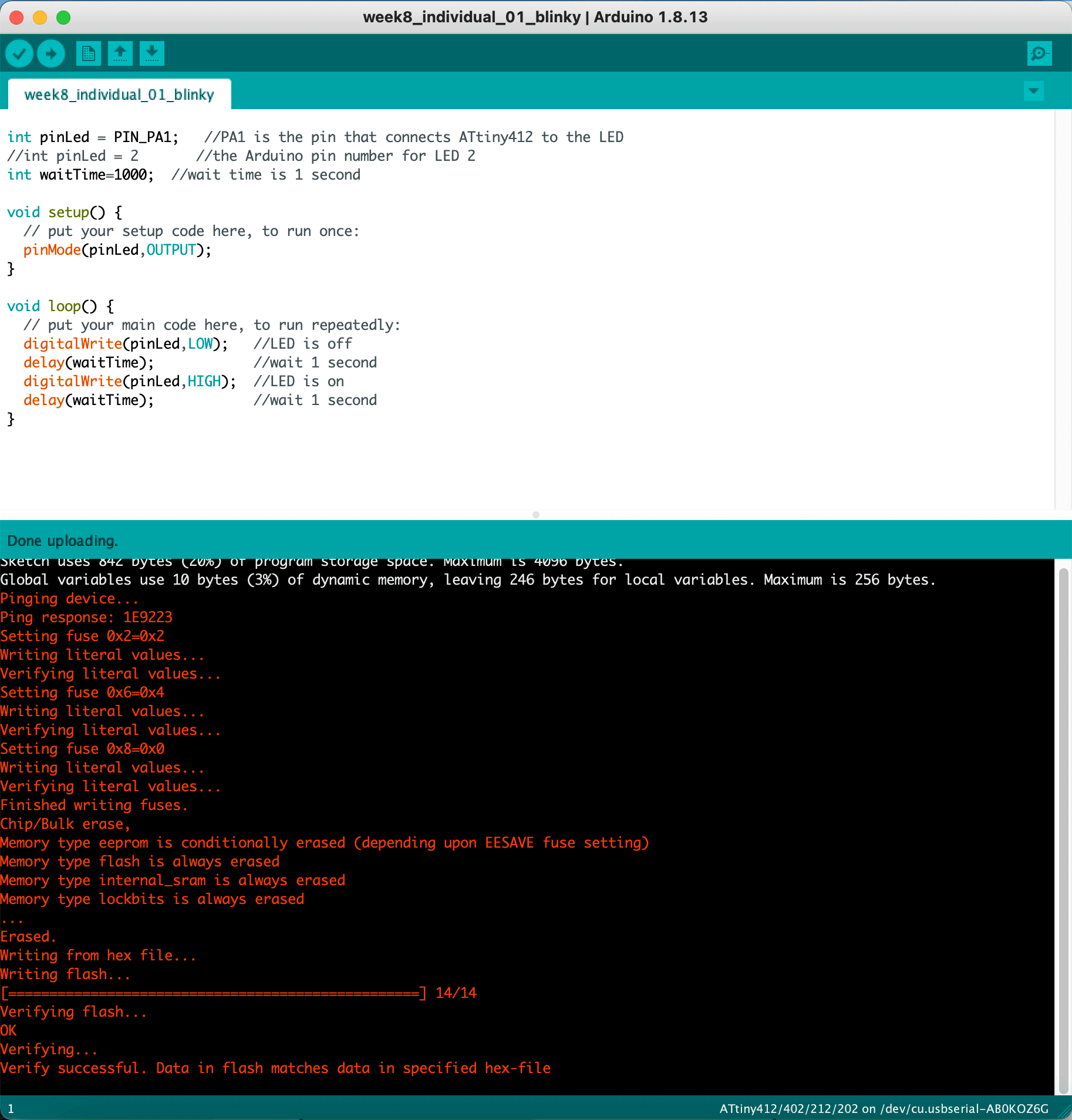
During the Electronics Design week, Nick has created an Arduio sketch to program and test our hello.t412.echo boards with a blinking LED (digitalWrite) and serial statements (Serial). It was now time to do it on my own! To begin, I set up the Arduino environment using the same settings as in Week 6 using a JTAG programmer and an UPDI adapter. Since I have already installed megaTinyCore on my Arduino IDE (tutorial) on Week 6, I would only need to perform the following.
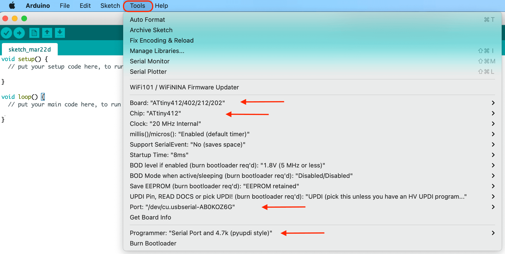
Under Arduino > Tools, I selected:
- Board: ATtiny412/402/212/202
- Chip: ATtiny412
- Port: "/dev/cu.usbserial-AB0KOZ6G" - this could be different for every one, but the port sould be a serial port
- Programmer: Serial Port and 4.7 (pyupdi style) - this is very important because selecting the incorrect programmer would not work
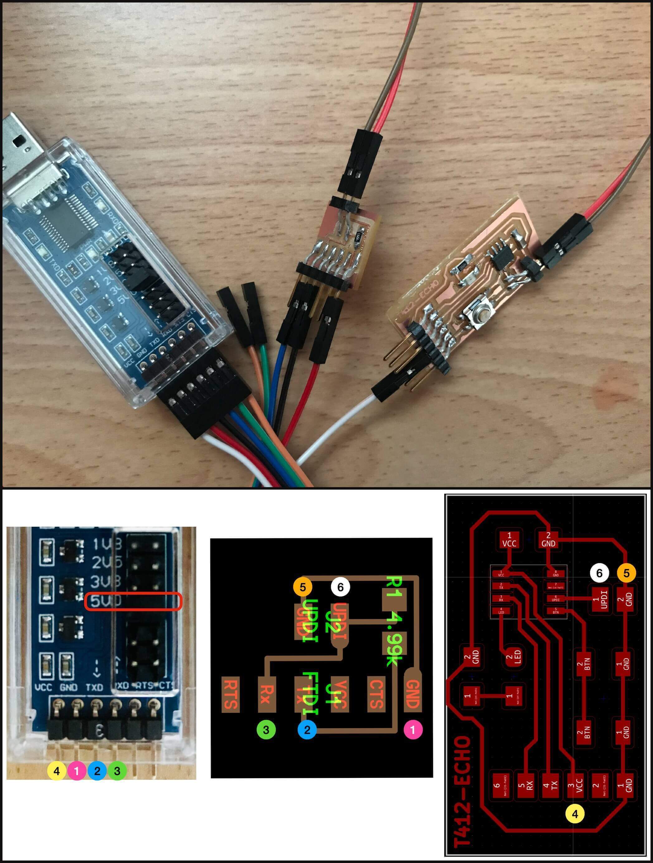
The wiring connection was as follows:
Blinking the LED
During the Electronics Design week, I spent a long time trying to debug the issue with my LED because it was not able to turn on. Later, I learned that the LED was not on because I had input the incorrect pin number for the LED in Arduino IDE. According to the Spence Konde's documentation, the pin number on the ATtiny412 microcontroller was different from the pin number for Arduino:
ATtiny pin number - PIN_Pxn, where x is A, B, or C, and n is a number 0-7 -
Arduino pin number - a single number.
In the first exercise, I used the digitalWrite function to realize a blinking LED. When the "OUTPUT" voltage was set to "HIGH", it meant that the corresponding voltage value was 5V, when it was set to "LOW", the corresponding value was 0V (ground).
Here is a short video of the blinking LED:
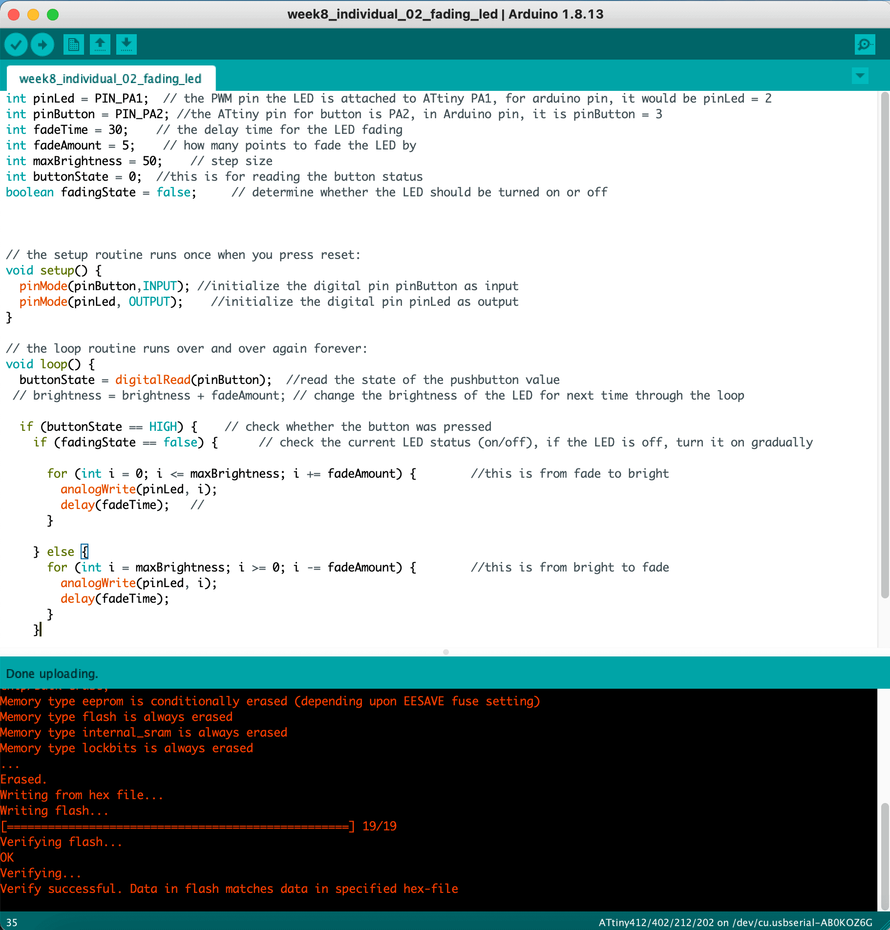
Fading the LED with a pushbutton
What if I wanted to use the voltange that was in between the 0V and the 5V? Is there a way to use those voltages? I looked up online and found that there was such way, and that would utilize the analogWrite function, and would result in a fading LED effect. The analogWrite() function uses Pulse Width Modulation (PWM), which can be identified with a "~" sign. I then checked the pinout for ATtiny412 and found a "2~" color block to the left of the "PA1", so I knew that I could fade my LED.
Next, I experimented my board with the Arduino Fade example:
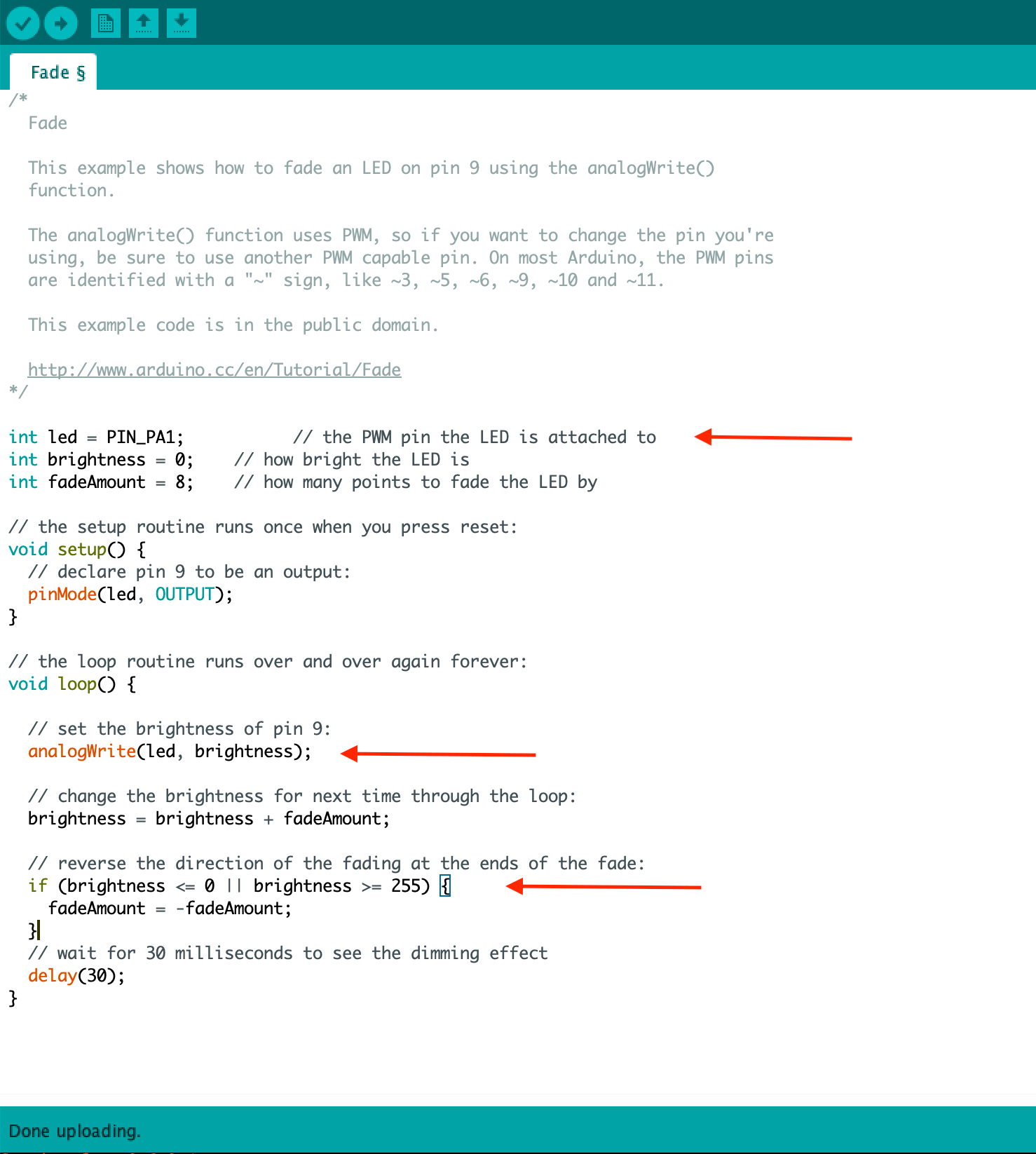
I learned that I would need to use the "if" statement to change the level of fadness of the LED... but why did the range of the brightness have to be between 0 and 255, was there a reason behind it? I researched online, and once again, Paul's video tutorial helped:
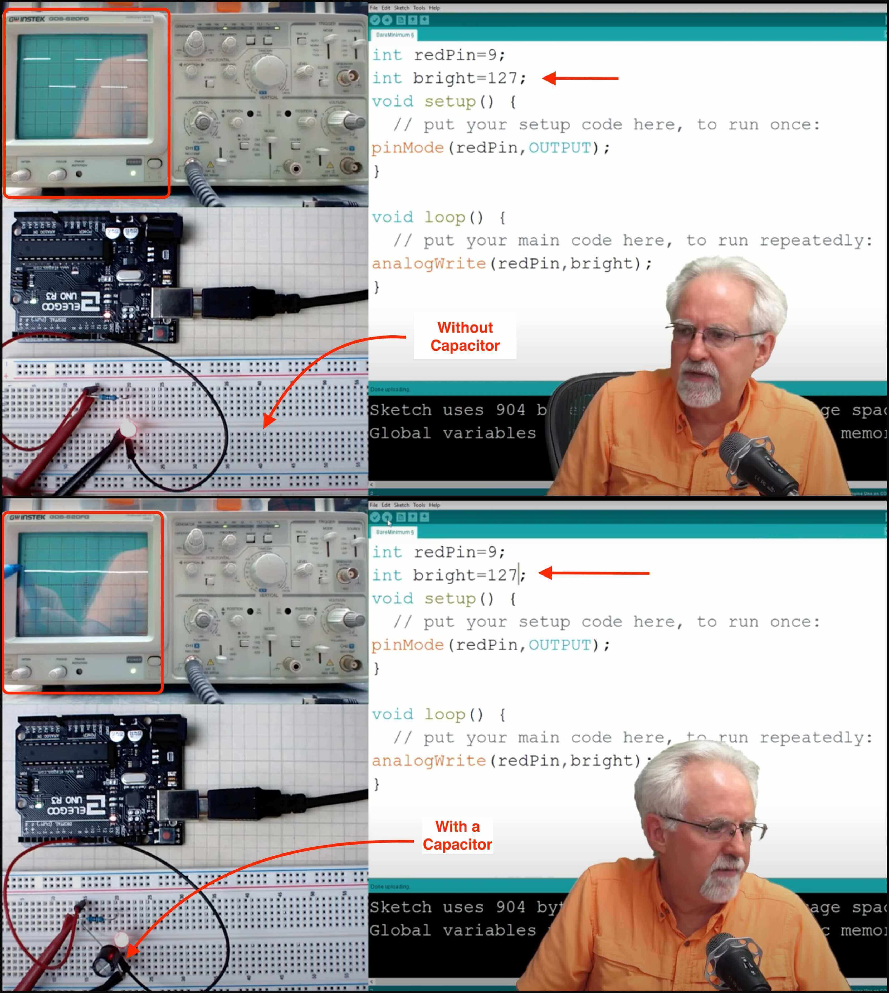
The values that we use for brightness are 0 to 255, that's basically 2^8, so that's like an 8-bit number; Between zero and 255 is 2^8 different positions or increments that we can do, so the brightness of 0 is equivalent to 0V, and a brightness of 255 would be equivalent to 5V or the same thing as digital right "HIGH".
Paul explained the concept of PWM through an oscilloscope. The PWM has a constant period and it's just changing at what fraction of that period the signal is on verses the signal is off. For example, if the brigtness value is 127, the scope is not creating 2.5V, but if we average over the period (5V vs. 0V) we get an average of 2.5V. If we want a true analog signal, we will use a capactior to smooth out the signal.
After understanding the concepts, I then incoroprated the button (digitalRead) to control the brightness of the LED:
Here is a short video of the fading LED showing a pulsing effect:
Files
Please find below the files that I made for this assignment.
- Group Assignment
- Individual Assignment