
This work is licensed under a Creative Commons Attribution-NonCommercial-ShareAlike 4.0 International License
Week 5: 3D Scanning and Printing
Mar 2, 2021Summary
This week's assignments
- Group assignment:
- Test the design rules for your printer(s) and explain what you learned from testing the 3D printers ✔
- Document your work and explain what are the limits of your printer(s) (in a group or individually) ✔
- Individual assignment:
- Design and 3D print an object (small, few cm3, limited by printer time) that could not be easily made subtractively:
- Document how you designed and made your object and explain why it could not be easily made subtractively ✔
- 3D scan an object, try to prepare it for printing (and optionally print it)
- Document how you scanned and prepared an object (for 3D printing) ✔
- Include your original design files for 3D printing (both CAD and common format for 3D printing) ✔
- Include your hero shots ✔
Resources Used
- Software: SOLIDWORKS, xDesign, Meshmixer, Ultimaker Cura (3D slicer software), Qlone (3D scanning app)
- Hardware: Creality Ender 3, Ultimaker 3 Extended, Sindoh 3DWOX 1
Skills Gained
- 3D Designing, 3D Printer Operation, 3D Scanner Operation
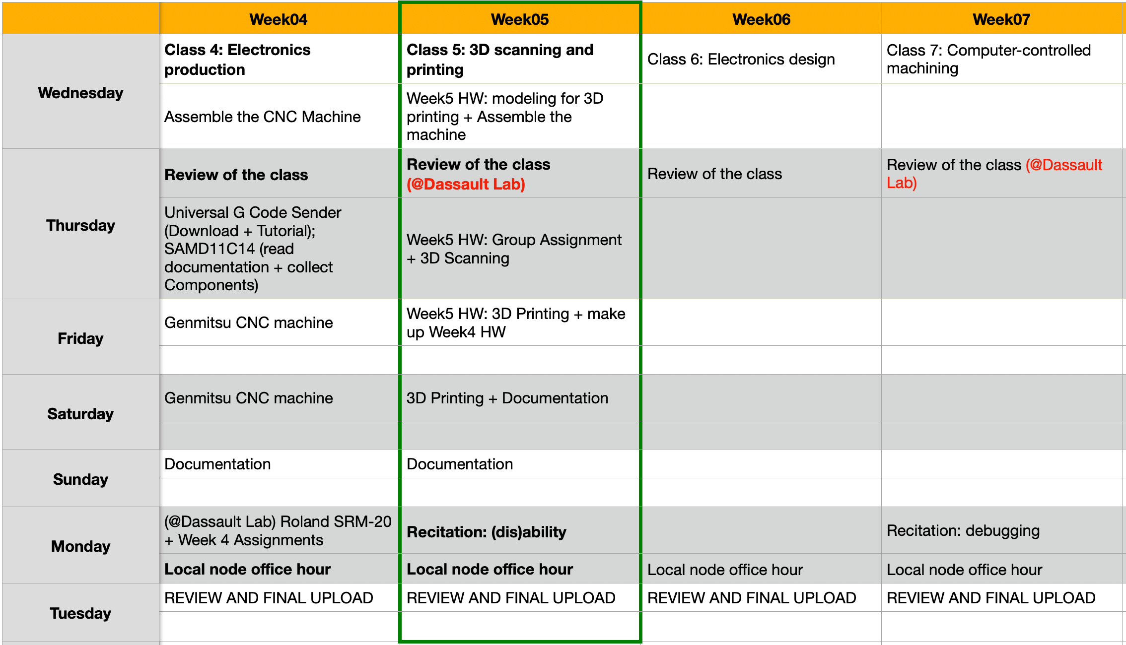
My Weekly Schedule
About the 3D Printer
Assembling & Calibrating the 3D Printer
Although I had some previous 3D printing experience, I was only scratching the surface. This week, I had the opportunity to build an Fused Deposition Modeling (FDM) machine, calibrate the machine, and make my first prints.
The 3D printer that we received was the Creality Ender 3 3D printer. Similar to the CNC router, the printer were nicely packaged and came with a nice instruction manual. While assembling my printer, I also referred to this YouTube video as I was not sure about the orientation for some components. The assembled machine looks very similar to a Prusa i3 MK3S, but is a cost effective option for hobbyists. When our instructor Greg told us that these machines would be for us to keep, I was ecstatic because I felt that I would be able to learn the machine and the technology in depth on my own.
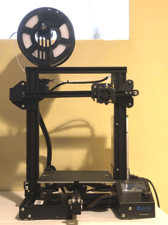
Here is some information for the machine:
- Model: Creality Ender 3
- Type: FDM
- Build Volume: 220 x 220 x 250 mm
- Nozzle Diameter: 0.4 mm
- Filament Diameter: 1.75 mm
- Layer Thickness: 0.1 - 0.4 mm
- Slicer: Cura
- Materials: PLA, ABS, Wood, Flexbile, PETG
- Temperature (Nozzle / Bed; ℃):
- PLA: 220 / 60
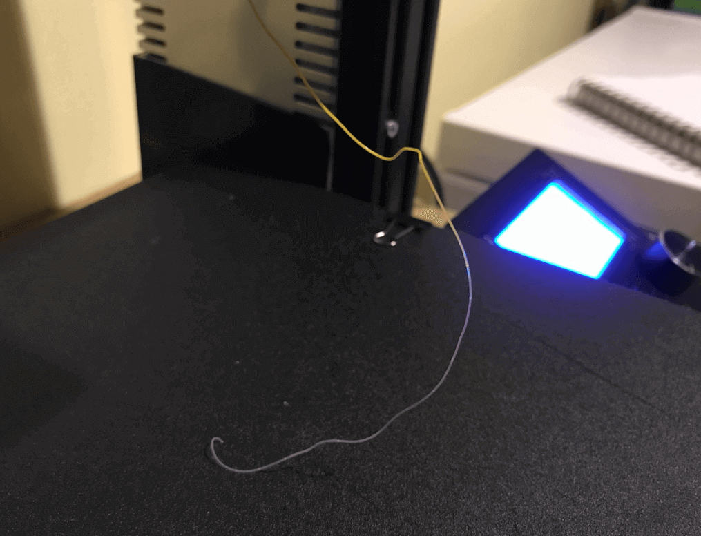
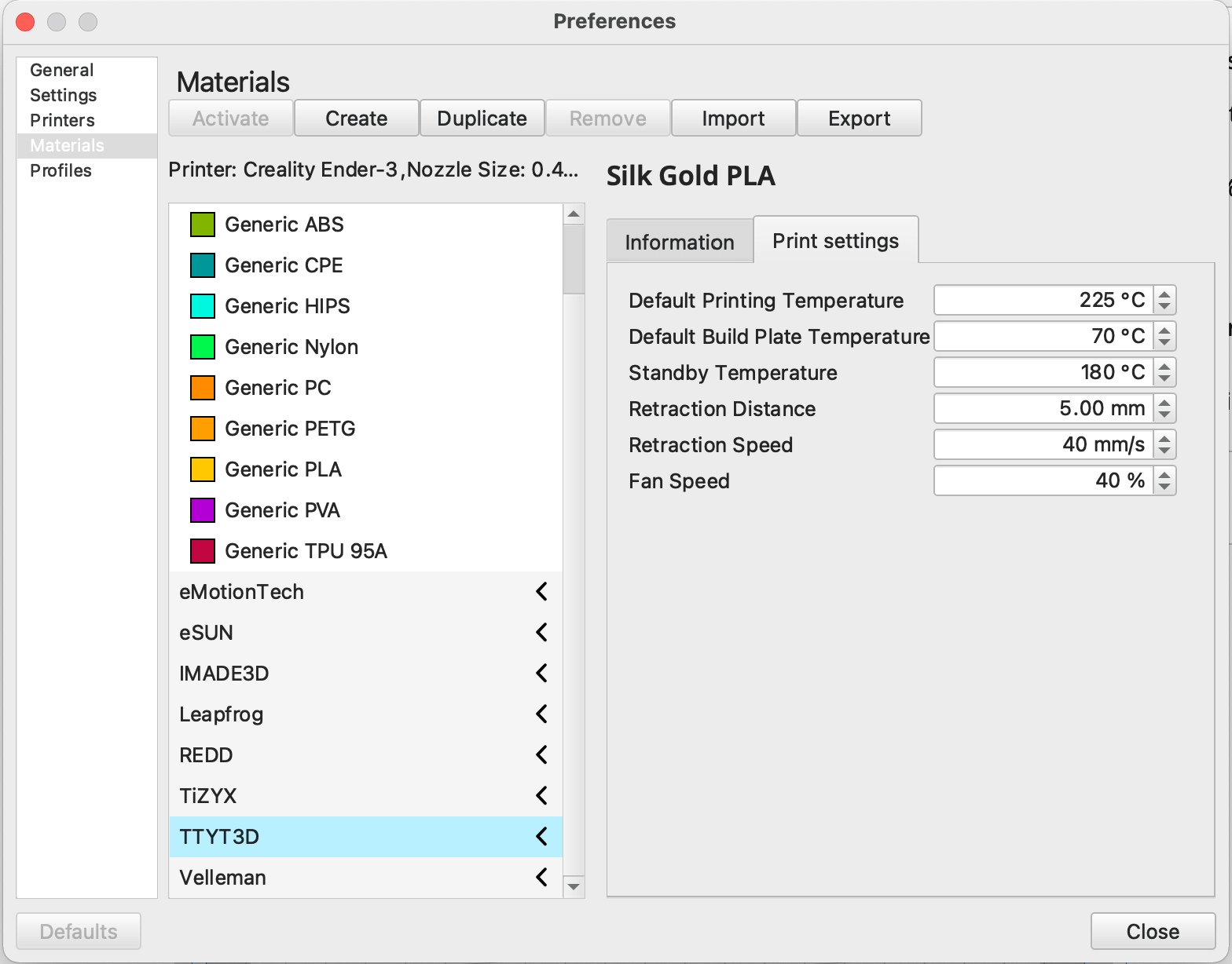
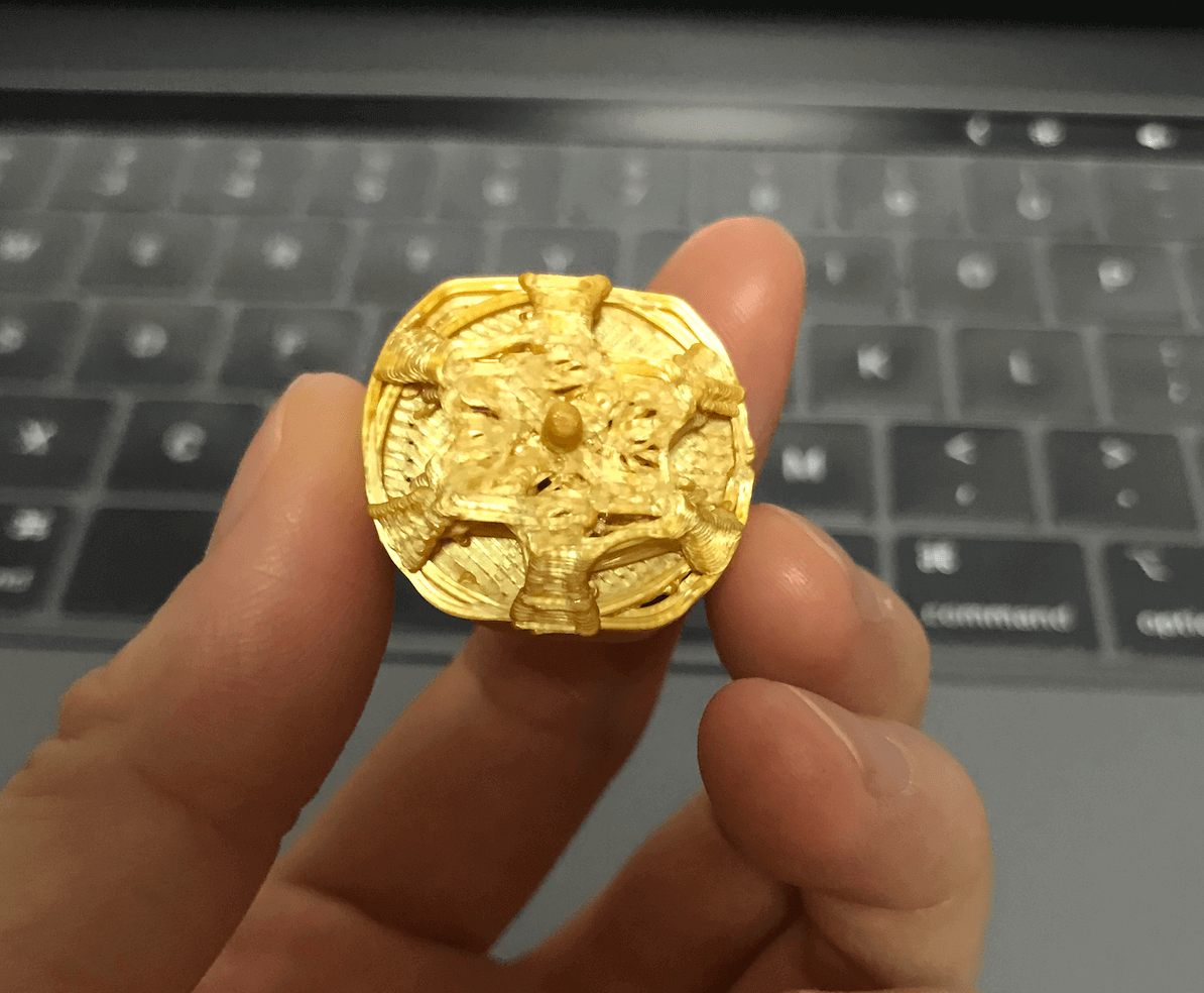
As I planned to use this Silk Gold PLA for some decorations on my final project, I decided to experiment with it this week. To begin, I needed to change the filament. I first heated the nozzle and the bed prior to unloading the original filament; I also prepared my new filament by cutting off the end at an angle of 45° for easier loading. Once I felt a firm resistance, I knew that the new filament has reached the nozzle, however, I kept pushing it until all the old filament was out of the nozzle as shown in the image below.
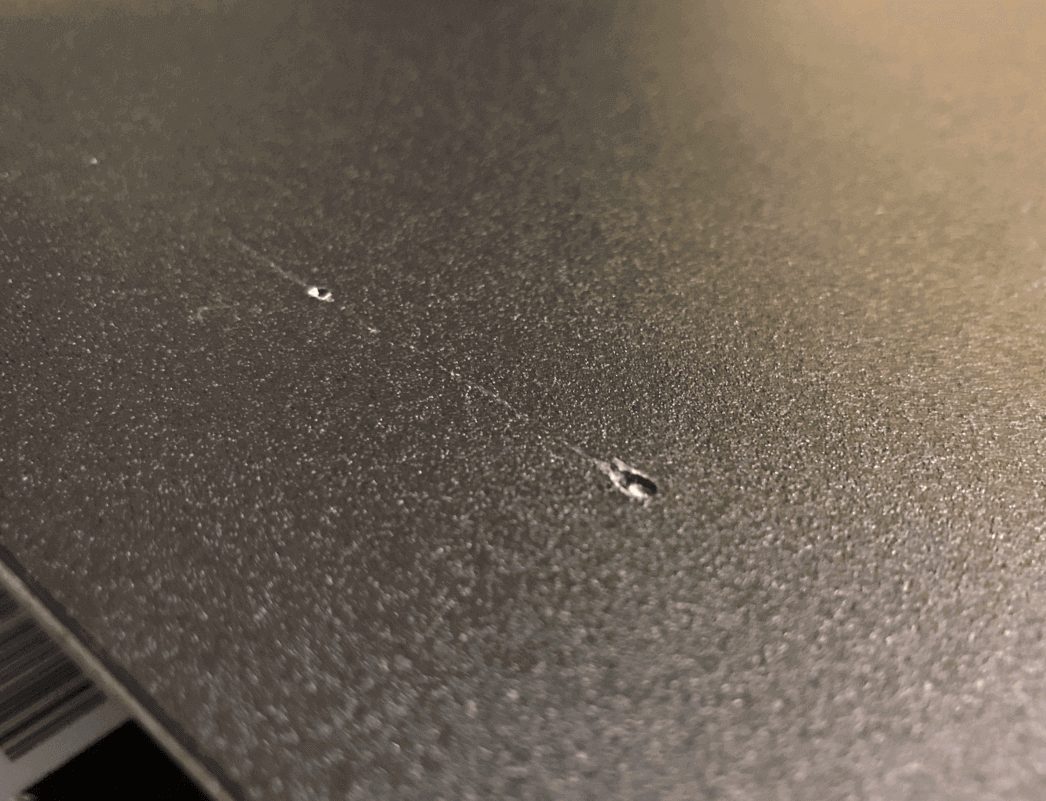
Everything seemed smooth for me until I ran the bed leveling test. I did not lower my bed before the leveling test, and as a result, the hot nozzle (200℃) scrapped the bed. I stopped the test quickly but nonethless, it left a mark. The mark did not affect the prints, but it was a good lesson for me to always lower my printer bed before running a leveling test.
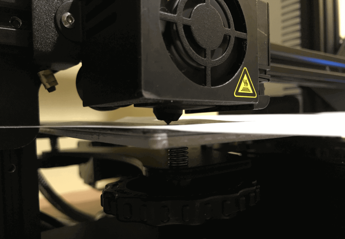
I made sure the 3D printer bed was as level as possible at all four corners and in the middle using a sheet of paper.
I should have also checked the "center square" of the printer bed since I would be doing most of my prints around that area on my printer.
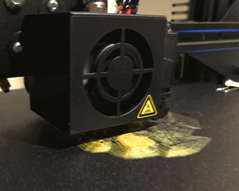
Later, I learned that the center left of my bed was actually slightly higher than the center right, and this was realized in the first layers of my first print, as shown in the image below. I stopped the print and used the scraping tool to remove the print, yet it was not as easy since it adhered to the bed quite strongly. Eventually, I was able to remove most of the excess by scraping on a heated bed (60℃).
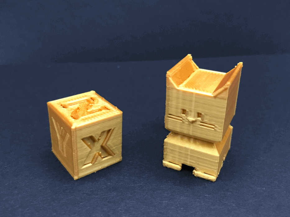
Learning from my mistake, I ran a bed leveling test again, and lowered / raised the corners so that the center square was leveled. I also printed out the Calibration Cube and the Cali Cat to ensure the bed leveling issue was fixed.
Charactizing the Machines
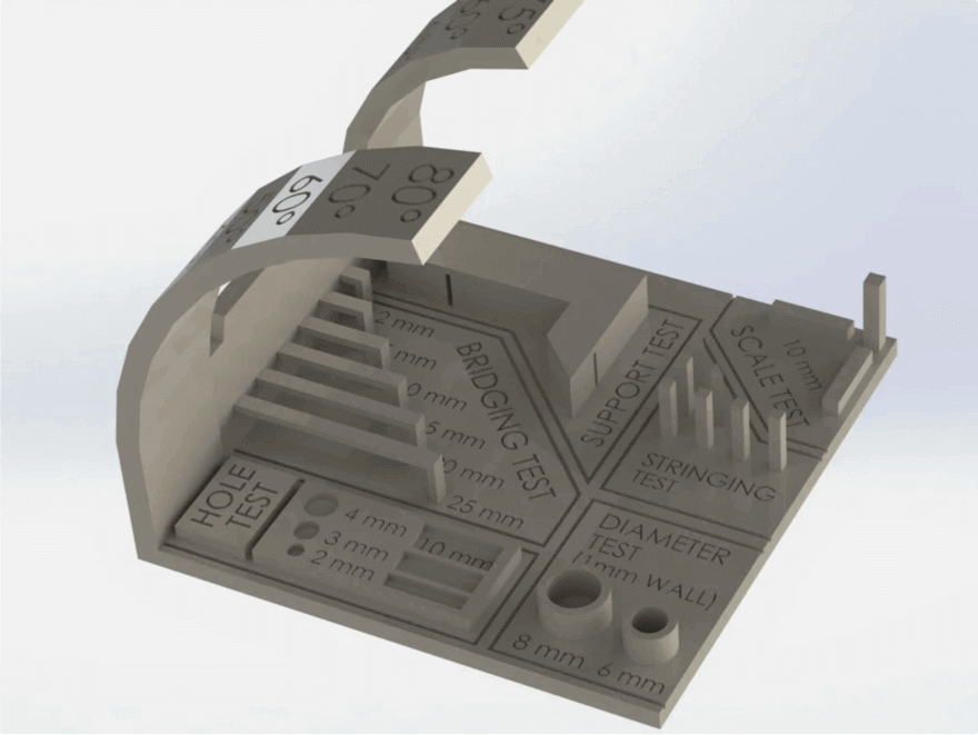
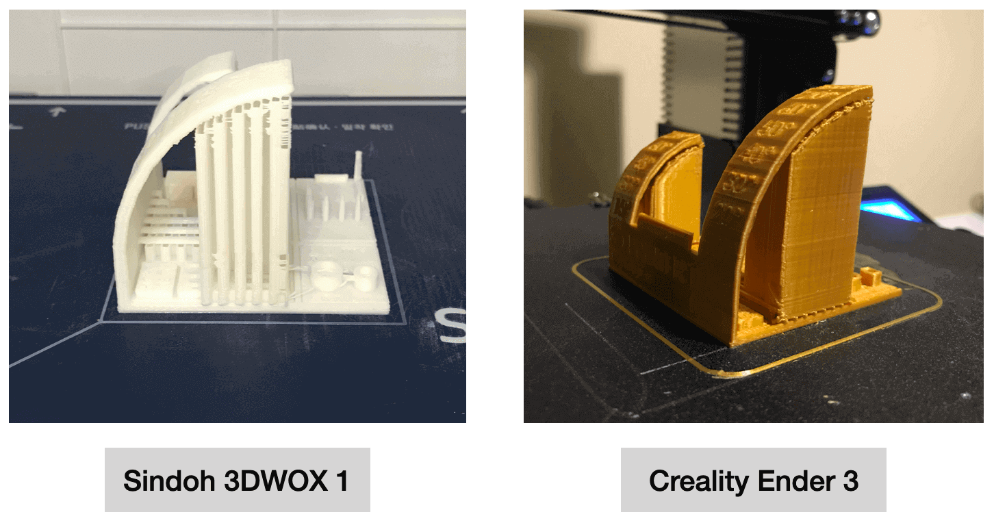
The group assignment this week was to test the design rules for our printer(s). Since I was at the lab last Thursday, I decided to print out this mini all-in-one 3D printer test as a reference to gauge the performance of my printer as well as the filament I was looking to use.
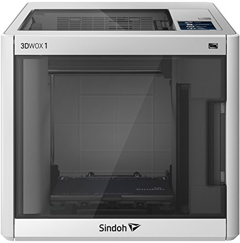
The printer that I used at the lab was the Sindoh 3DWOX 1, and here is some information for this printer:
- Model: Sindoh 3DWOX 1
- Type: FDM
- Build Volume: 210 x 200 x 195 mm
- Nozzle Diameter: 0.4 mm
- Filament Diameter: 1.75 mm
- Layer Thickness: 0.05 - 0.4 mm
- Slicer: 3DWOX Desktop Slicer
- Materials: PLA, ABS, PETG
- Temperature (Nozzle / Bed; ℃):
- PLA: 200 / 60
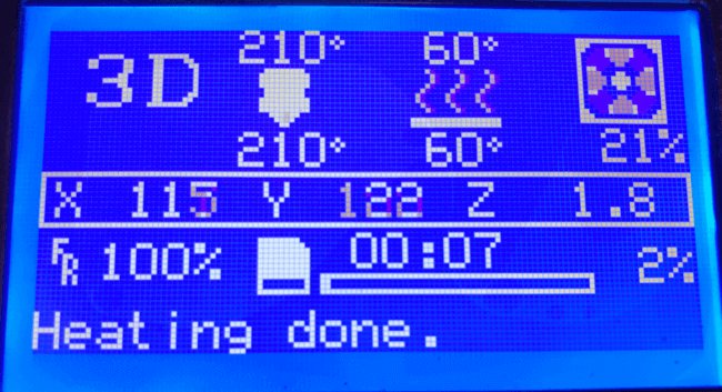
When printing the test model with the Silk Gold PLA filament, I initially used the same settings as on the Sindoh printer (Nozzle Temp. / Bed Temp. / Fan Speed = 200℃ / 60℃ / 100%). However, I quickly realized that this material should be treatly differently. One thing I noticed from the silk PLA material was that it tended to dry before adhering to the bed.
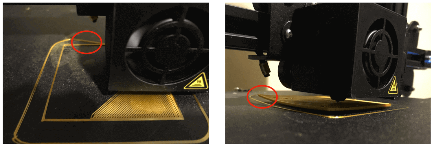
In order to fix this issue, I had to reduce my fan speed. I tried 70%, but still resulted to the same warping edge, then I tried 40%, still not helping, eventually I had to reduce to about 25% while raising my nozzle temp. and bed temp. to 225℃ and 70℃ respectively. I kept this temperature settings for the first few layers, once I made sure the print stayed on the bed, I then lowered the temperatures to 210 and 60, respectively, as recommended in this thread.
The design on the Ender 3 took about 5.5 hours to finish, which was 2 more hours than the Sindoh machine.
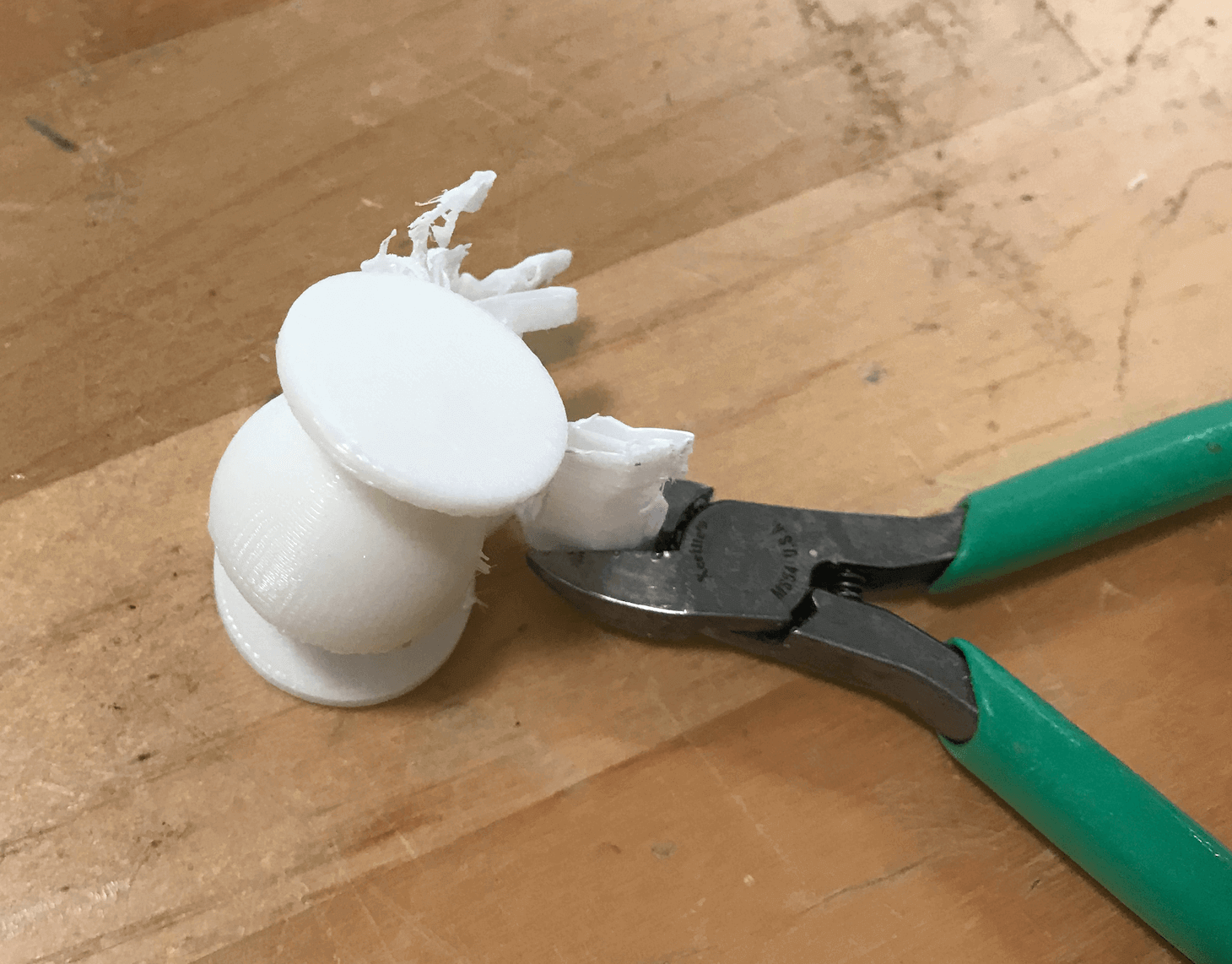
I used the provided clipper to trim off the supports before comparing the results. But...
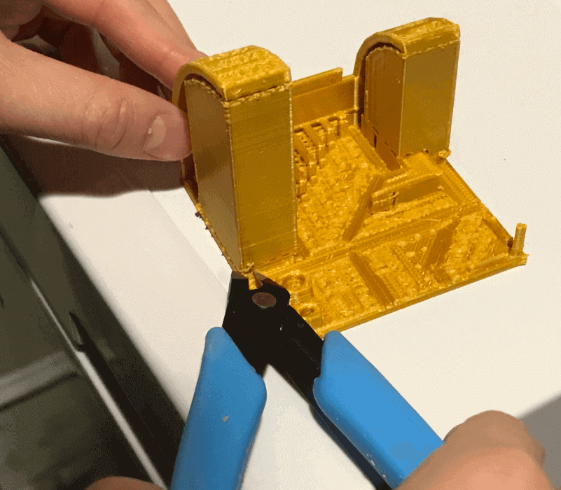
I over-trimmed the supports!! 😓 As a result, I was not able to show the results of the bridging tests or the stringing test. Fortunately, I observed the process and also felt the textures of the bridges / strings before removing them, so I still had a vague impression of how they were compared to each other.
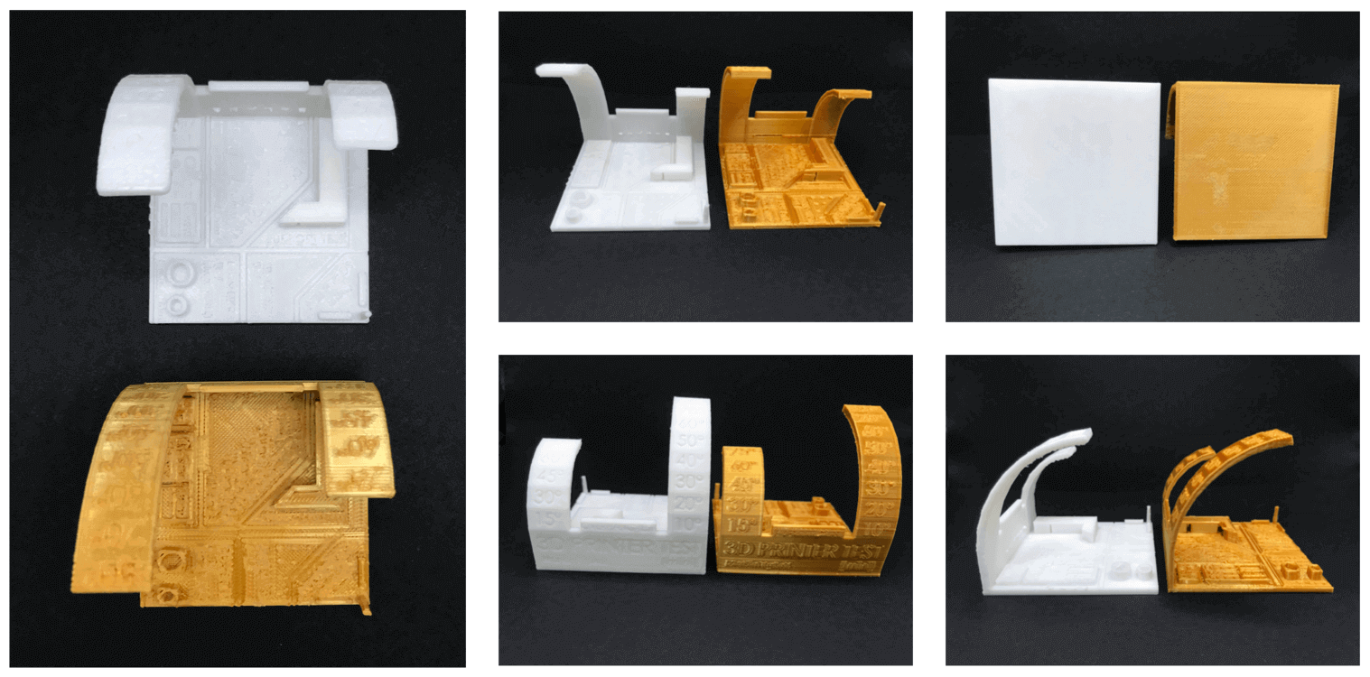
Due to the brittleness of the silk PLA material, it was not able to form round edges as well as a regular PLA, and this issue was magnified when I attempted to print a motor.
3D Printing
Part 1: Mini Vase
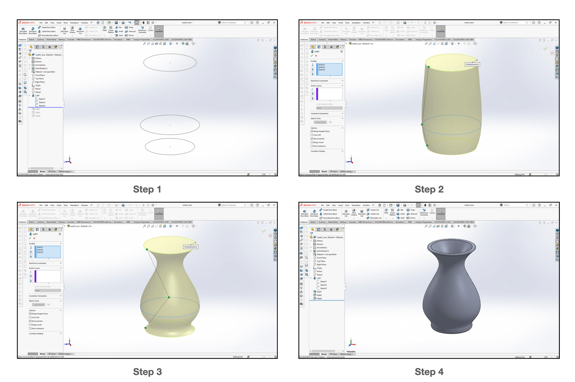
The night before our review session, I created a mini vase (16 x 16 x 30 mm) using the loft feature in SOLIDWORKS. I started by sketching three circles on reference plates of differnt heights, and realized the shape of the vase by twisting the connecting points of the Loft feature.
I wanted to experiment with voronoi pattern so I referred to this tutorial to create a hex-grid lattice pattern on my vase.
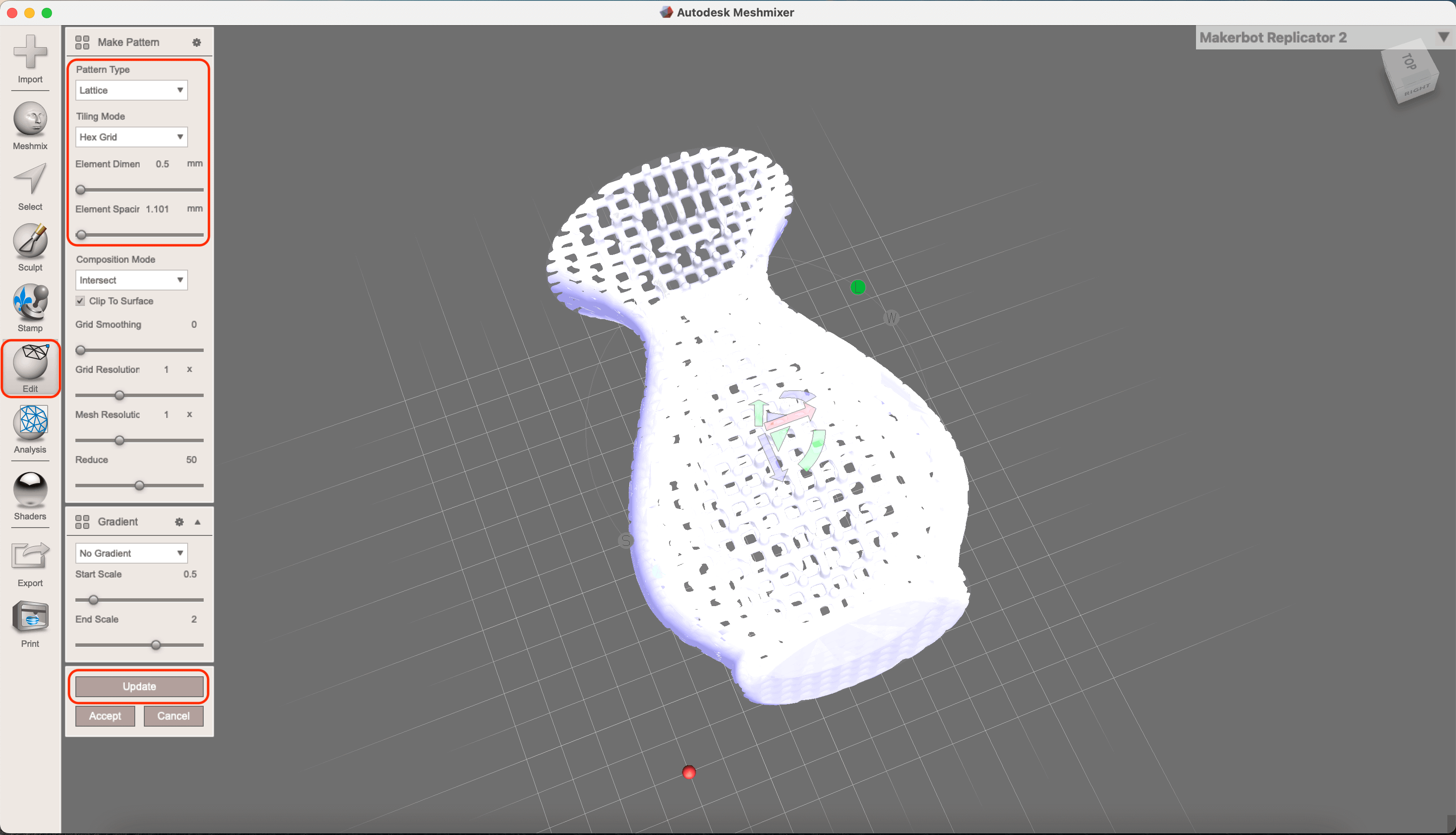
And here is the model of the voronoi pattern mini vase:
As this was my first time to try something with a voronoi pattern, I asked my instructor and my classmates for advices regarding using supports on the slicer software. I was told that this vase probably would not need supports, however, it could be too small to print out the fine details. And they were right - as you can see from the image below, my vase looked so tiny compared to the printer bed!
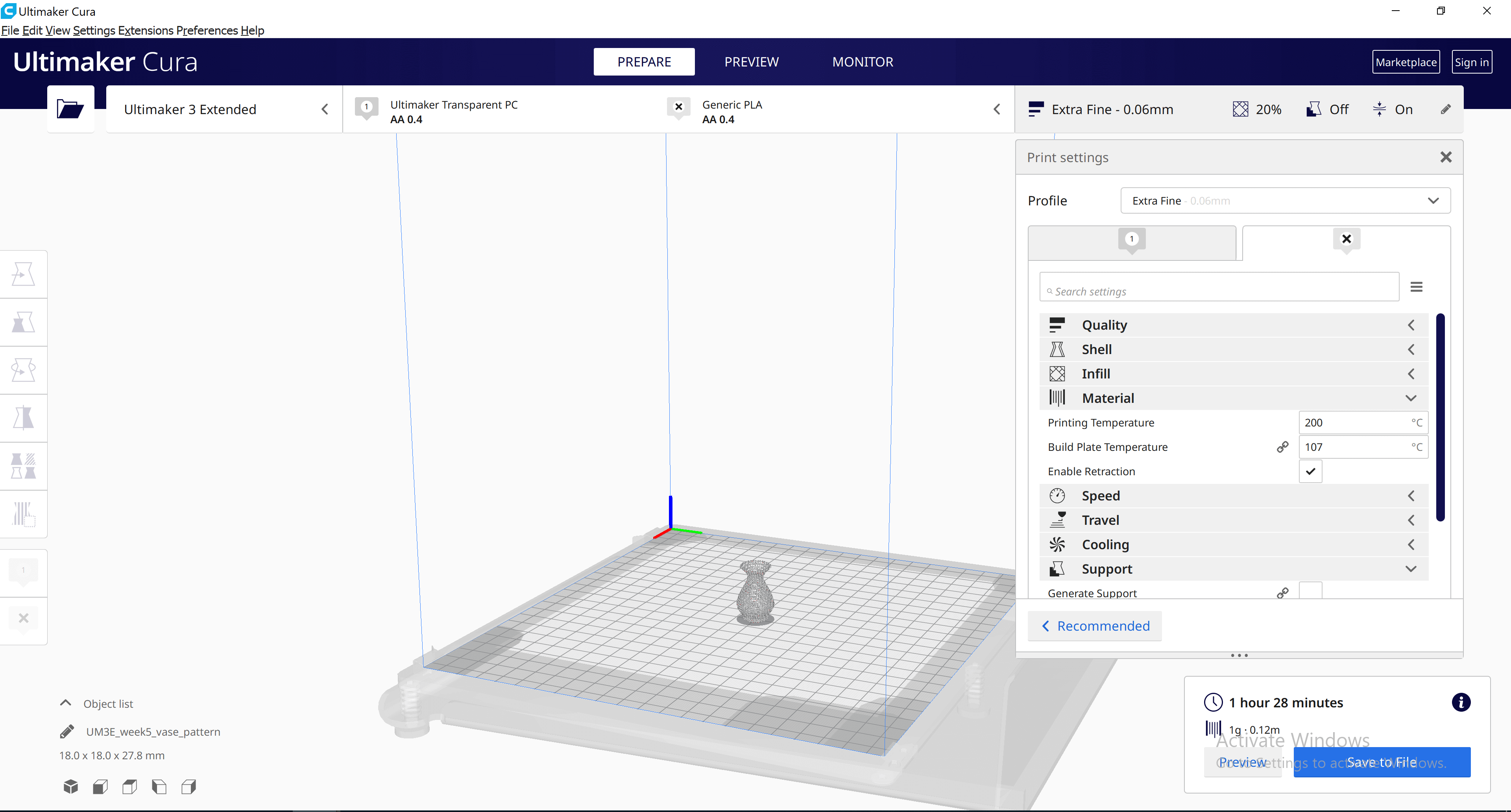
I learned that the minimum size of a voroni pattern for a printer would be 0.4 mm, so I would need to enlarge my model before doing the voronoi print. As I still wanted to try out my vase design before I left the lab on that day, I decided to print the non-voronoi version of the vase out of the Ultimaker 3 Extended printer at the lab. The material that I used was a transparent Polycarbonate (PC), and I had to print it with the Extra Fine quality. The design took 1 hour to print so I was able to bring it home with me 😊.
Part 2: Lofted Finger Massager
After learning the limitation of my silk PLA filament, I decided to create someting that didn't start and / or end up with a circle for my print on this week's assignment. The first idea that came to my mind was a stick realized by hexagons and circles. I chose to print it with the silk gold PLA on my Ender 3.
And this is how it looked:
This model did not require supports and took a little over 1 hour to print using the standard settings.
I made sure the first few layers went well before I left my printer alone, and I checked back every 30 min or so to make sure things went as intended. While observing the process, I noticed some artifacts built up along the side of the print, so I looked up online to see if there was a resolution. According to this page, the bubbles occcured due to several reasons, and most of them were accounted for high moisture cotent of the filament, with one of the reasons for printing at high temperature. Reading through this, I knew that I would need to balance the fan speed and the temperature settings, and the ones that I decided previously was not the optimal one.
I revisited the online reviews for this filament and I learned that printing it with a nozzle tempperature of 205 ℃ and bed temperature of 60 ℃ on a glass bed fixed the problem for most. I decided to give the glass bed a try.
Part 3: Ball-and-Socket Joint
The individual assignment for this week was to design and 3D print an object (small, few cm3, limited by printer time) that could not be easily made subtractively. In order to make the voronoi pattern visible, I would need to make the model 3 times larger, but the print time for the scaled voronoi vase would be ~ 8 hours, thus it would not fulfill the requirement of "limited by printer time". After spending some time brainstorming, I decided to model a ball-and-socket joint, and 3D print the assembly. I picked this idea because it is related to the biomechanics (i.e. the hip and shoulder) in our body. This is a design that could not be made subtractively because the end mill would not be able to travel inside the socket to mill the sphere. In this case, I would choose the additive manufacturing process to achieve the result.
I started by making the ball and socket part models in SOLIDWORKS, and created the assembly of the two model. Here is how the final assembly looks:
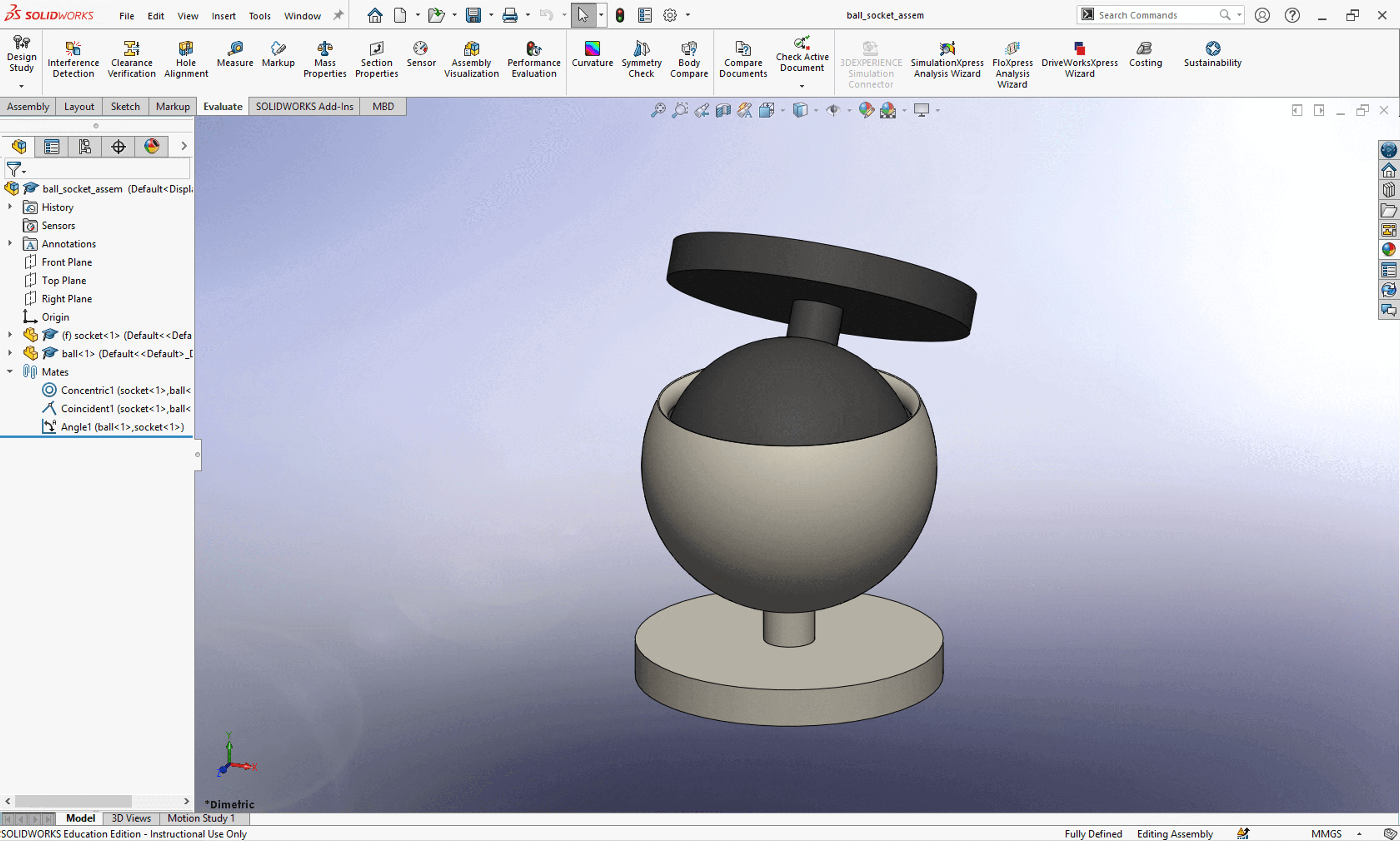
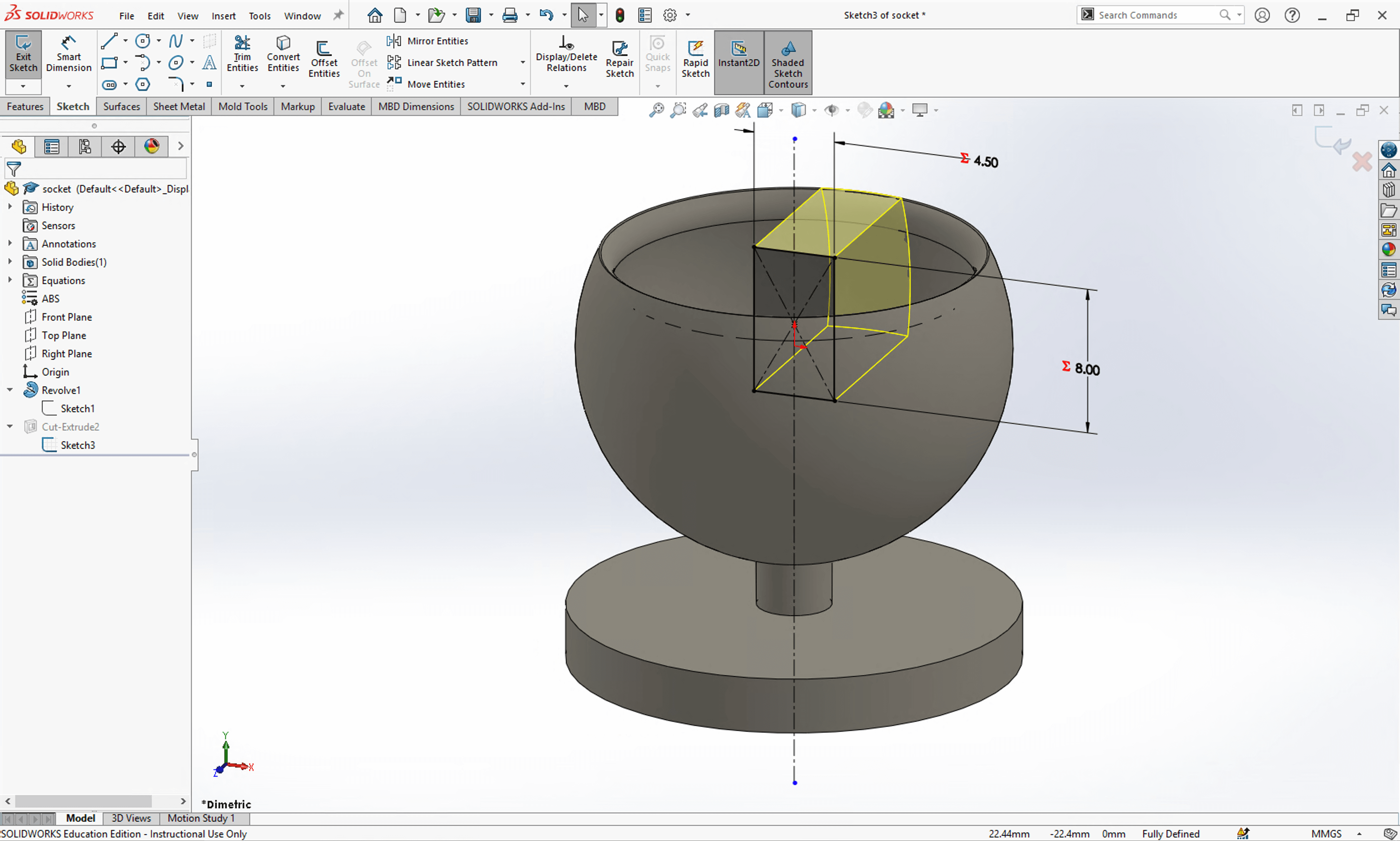
And this is how the part models look, the first image is for the socket, and the second image is for the ball:
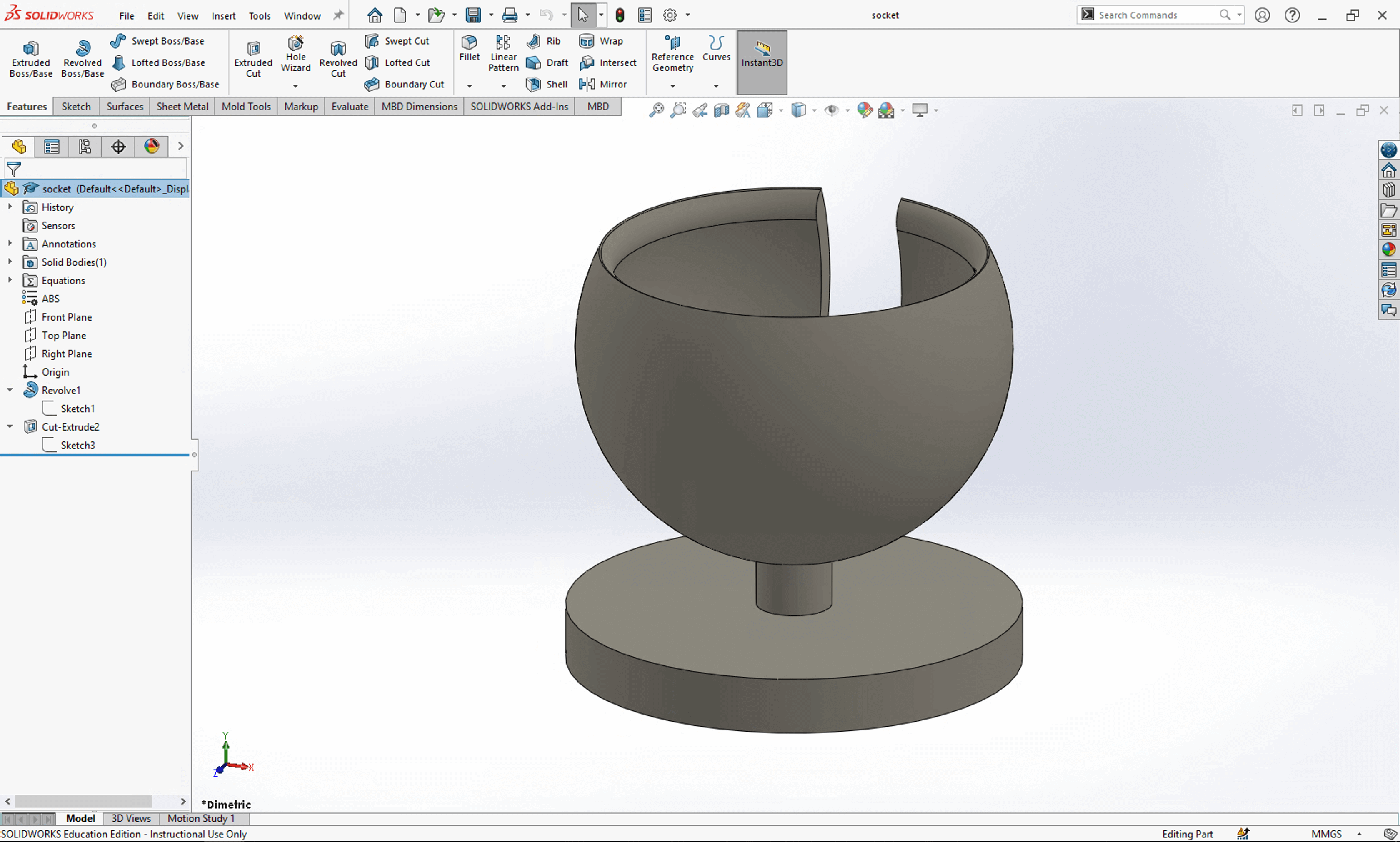
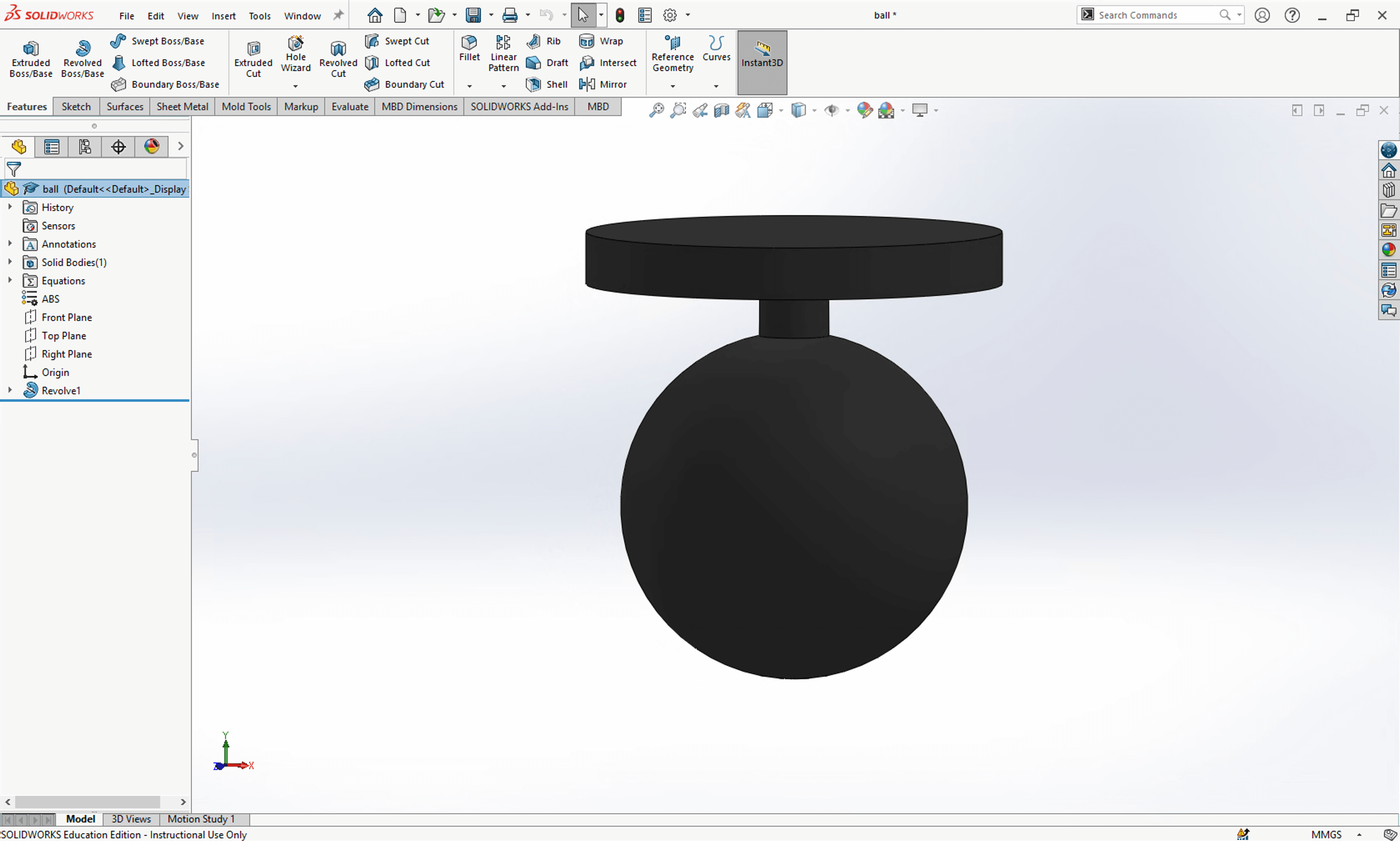
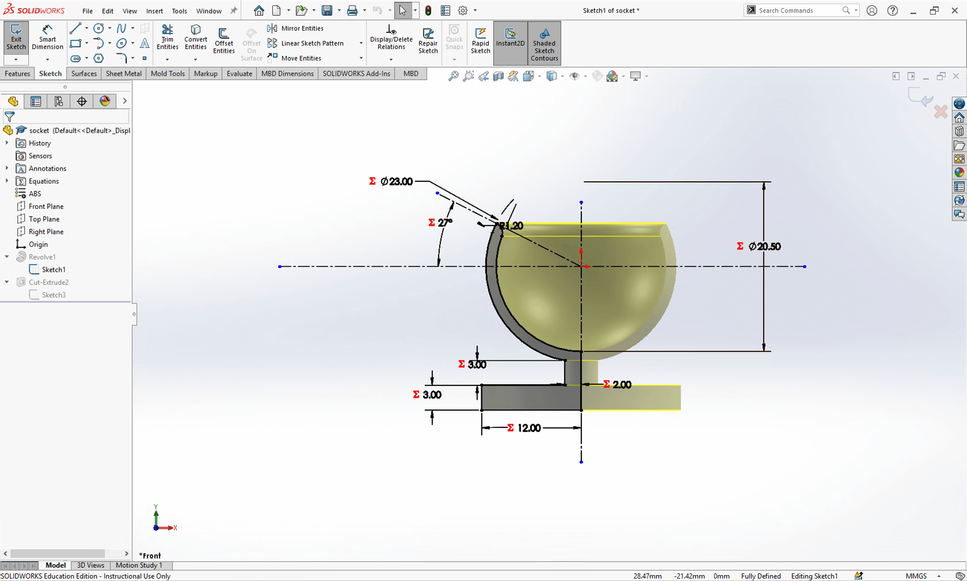
Both models were realized by the revolve feature. Since I wanted to print the assembly as a part, I made the socket slightly larger than the ball to create the space needed to seperate them. In here, I set the inner diameter of the socket as 21.2mm, and the diameter of the ball as 20mm. The two images below show the sketch before the revolve feature.
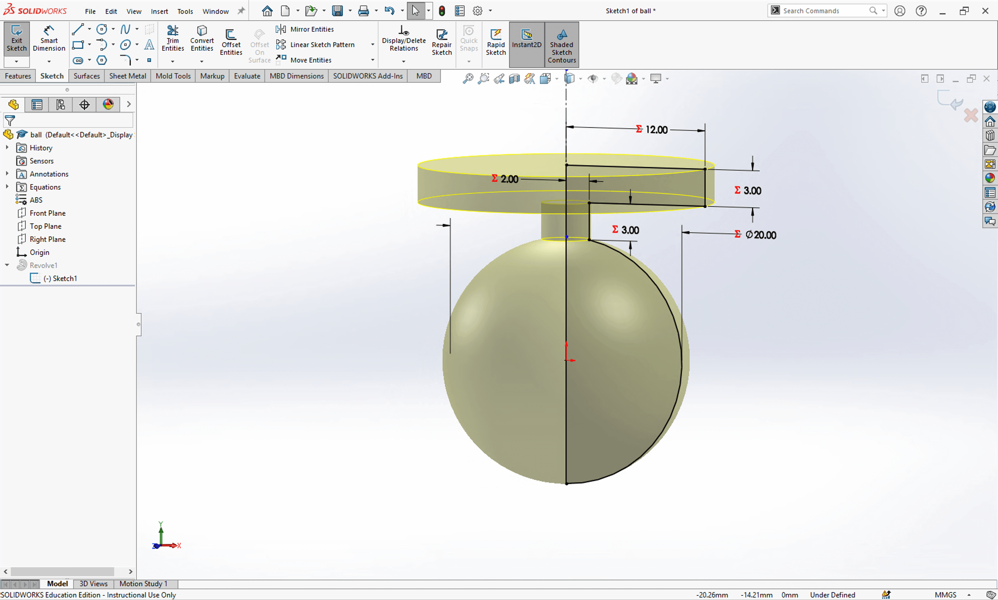
I added a slit in the socket model, as a rest area for the neck of the ball.
Once I was happy with the part models, I proceeded to create the assembly model. I used concentric and coincident mates and also set the two models at an angle of 30 degree to minimize the number of supports.
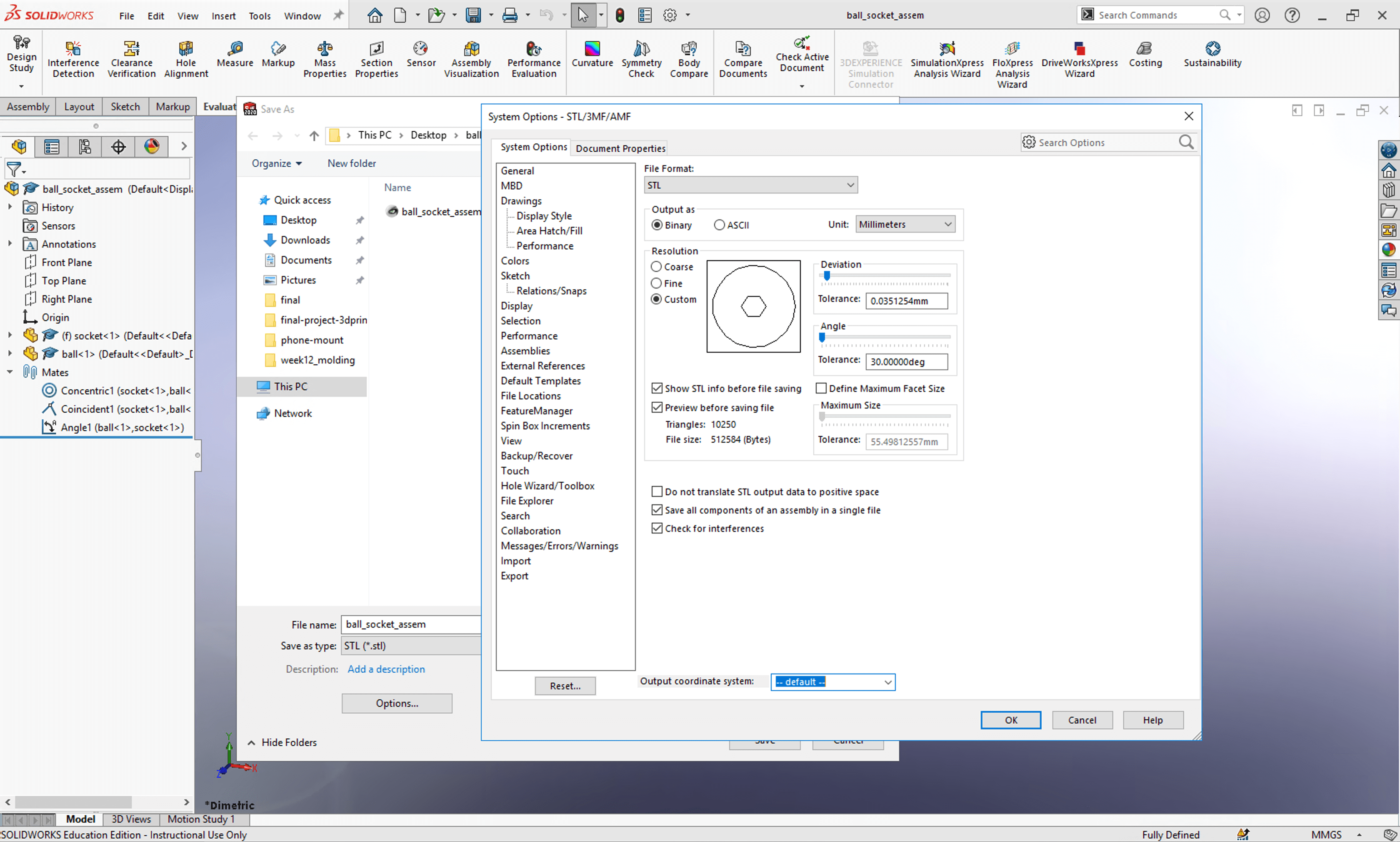
Then I exported the assembly as an .STL file. in the setting, I used custom resolution and checked the option of Save all components of an assembly in a single file.
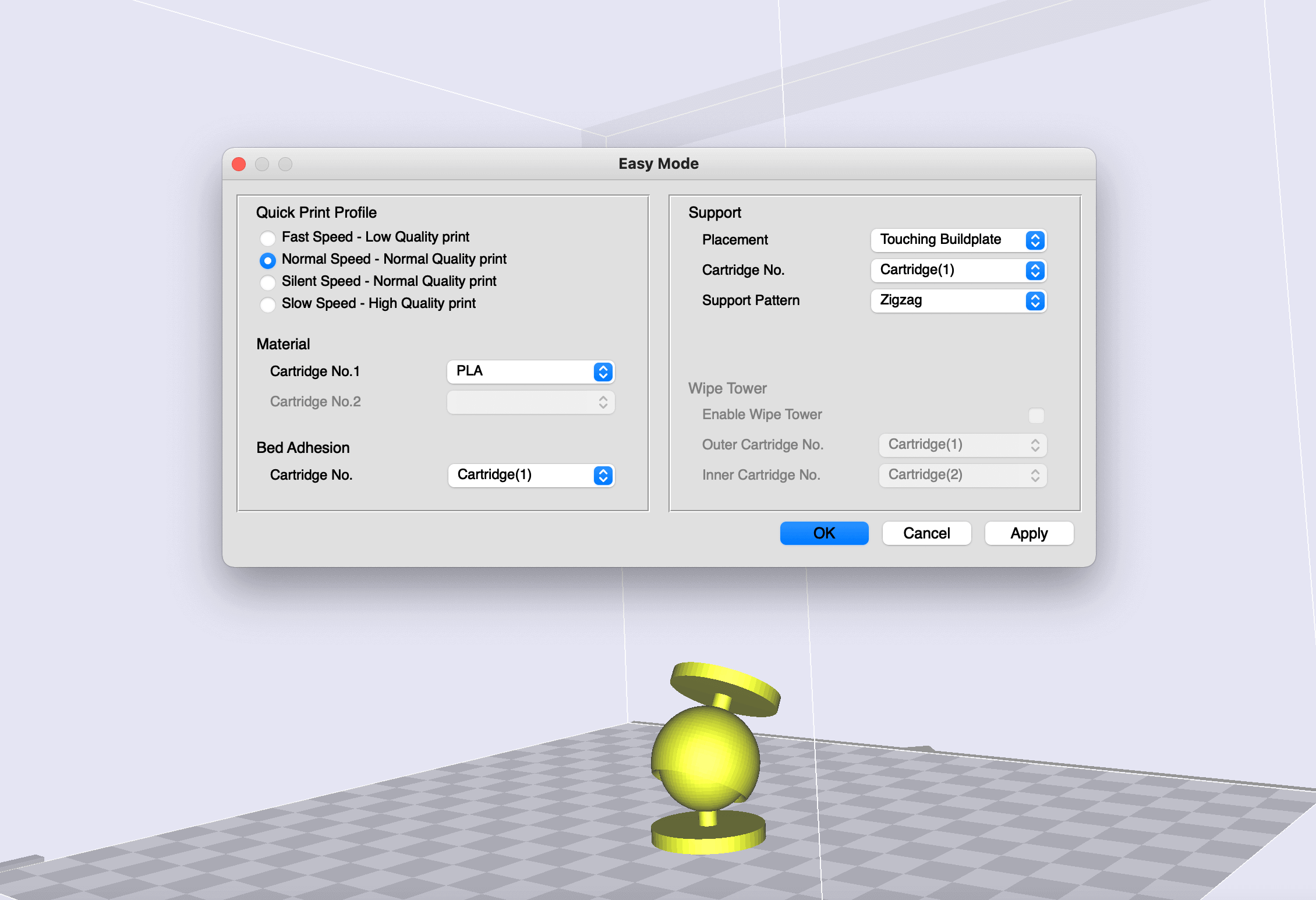
The printer that I was going to use was the Sindoh DP200 in the lab, and the filament would be a white PLA. The slicer for this printer was 3DWOX. As there were overhang in the model, I needed to add supports. I picked the option of Touching Buildplate and Zigzag pattern. Based on my previous experience, the print quality from the Sindoh machines was very high, so I picked Normal Speed - Normal Quality print in the Profile section.
I clicked OK to confirm the selection. I generated the G-code by clicking File > Save G-code. And this is how the preview looks. The support would be facing the front of the printer.
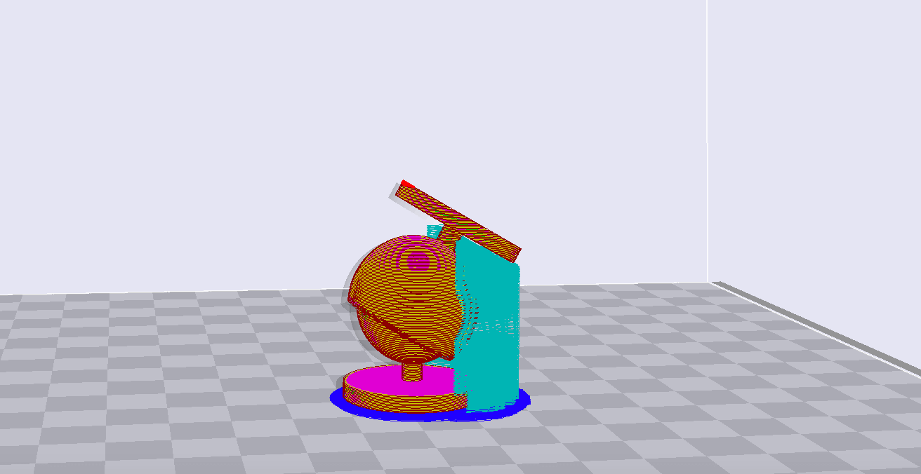
The print time would be 1 hour 2 minutes, and here is a short video from the slicer showing the evolution of the print:
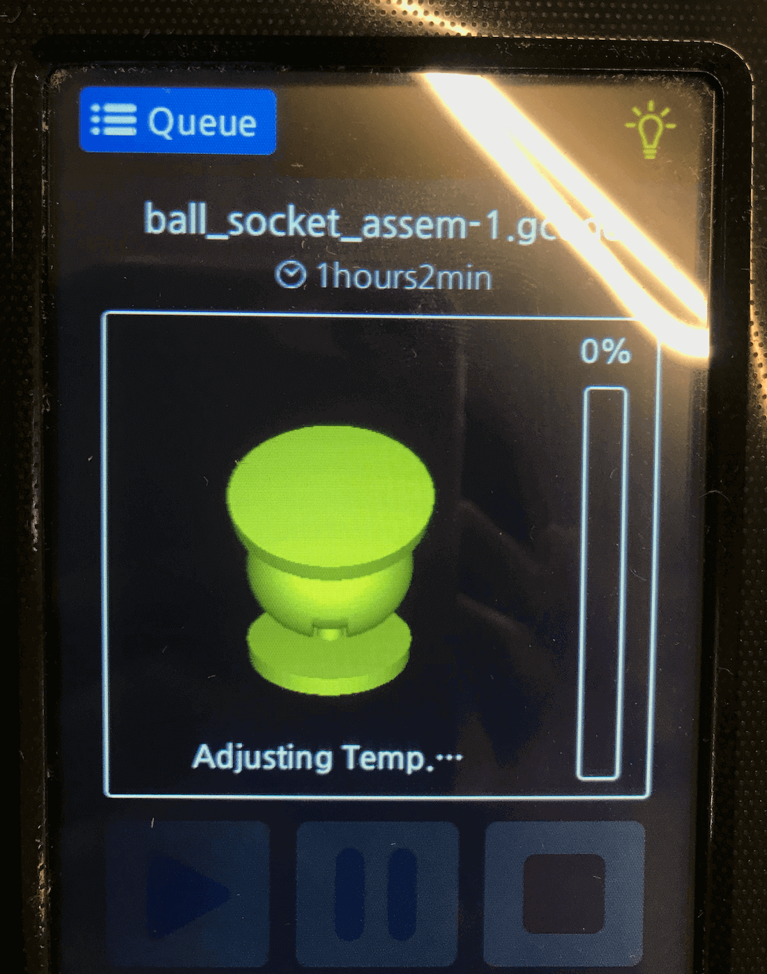
A nice thing about the Sindoh machines was the cloud print, as I didn't have to use an USB to save my G-code. This is how it looked on the machine's user-interface.
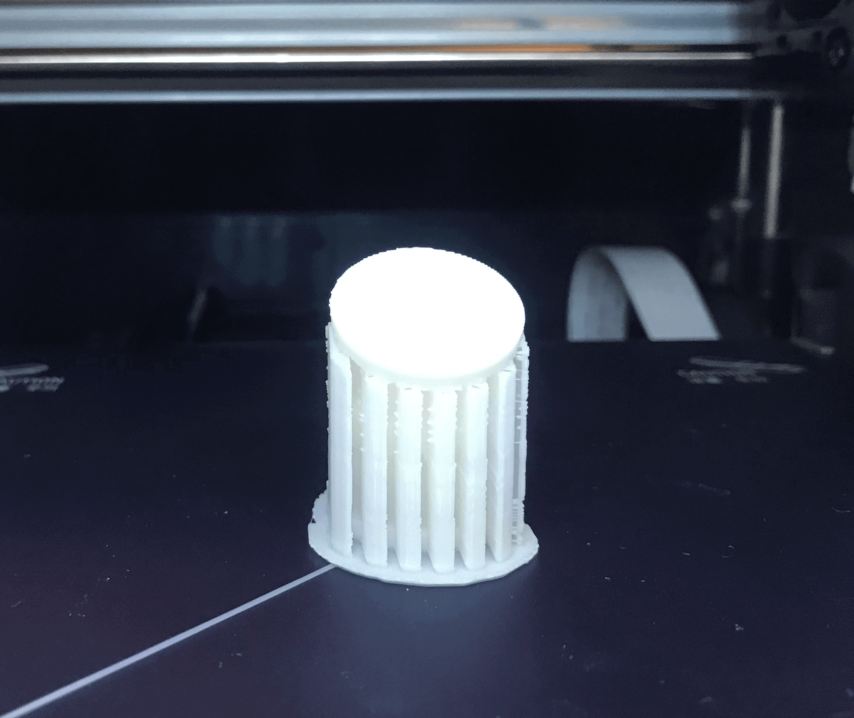
I made sure the first few layers were fine before leaving to work on other projects. Here is a short video showing the printing process.
This is how the final model looked, before removing from the printer bed.
I found that the edge of the socket was not very smooth, I guess it was because I printed the model upside down.
Next, I used a snipper to carefully remove the support. I needed to be gentle because the necks of the ball and the socket were thin.
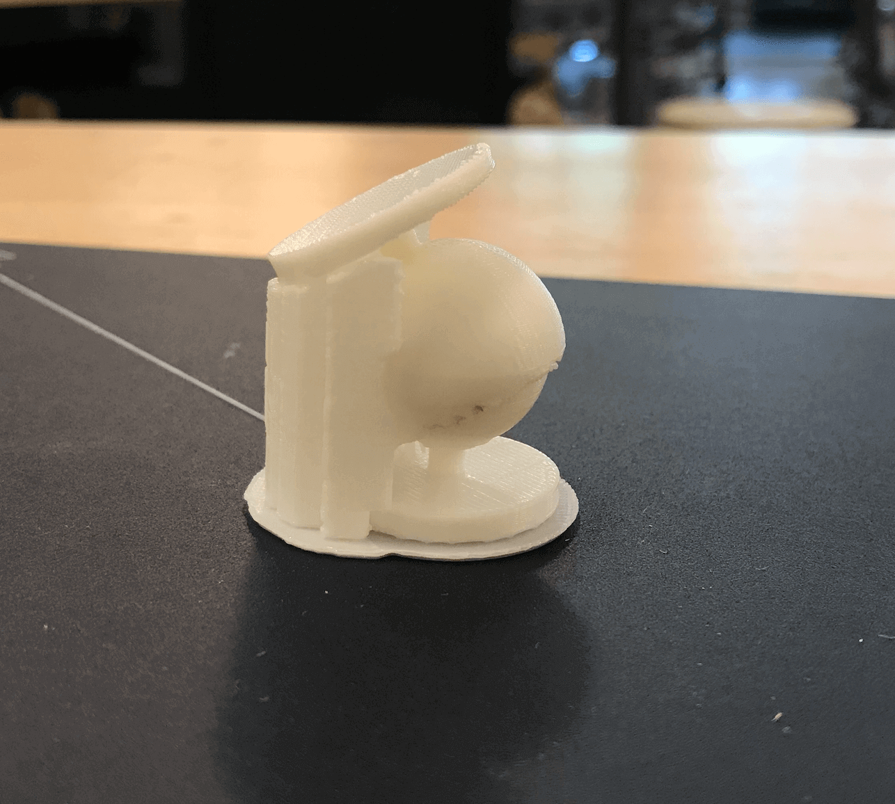
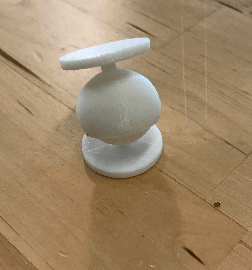
Here is how the assembly looked, after removing the supports.
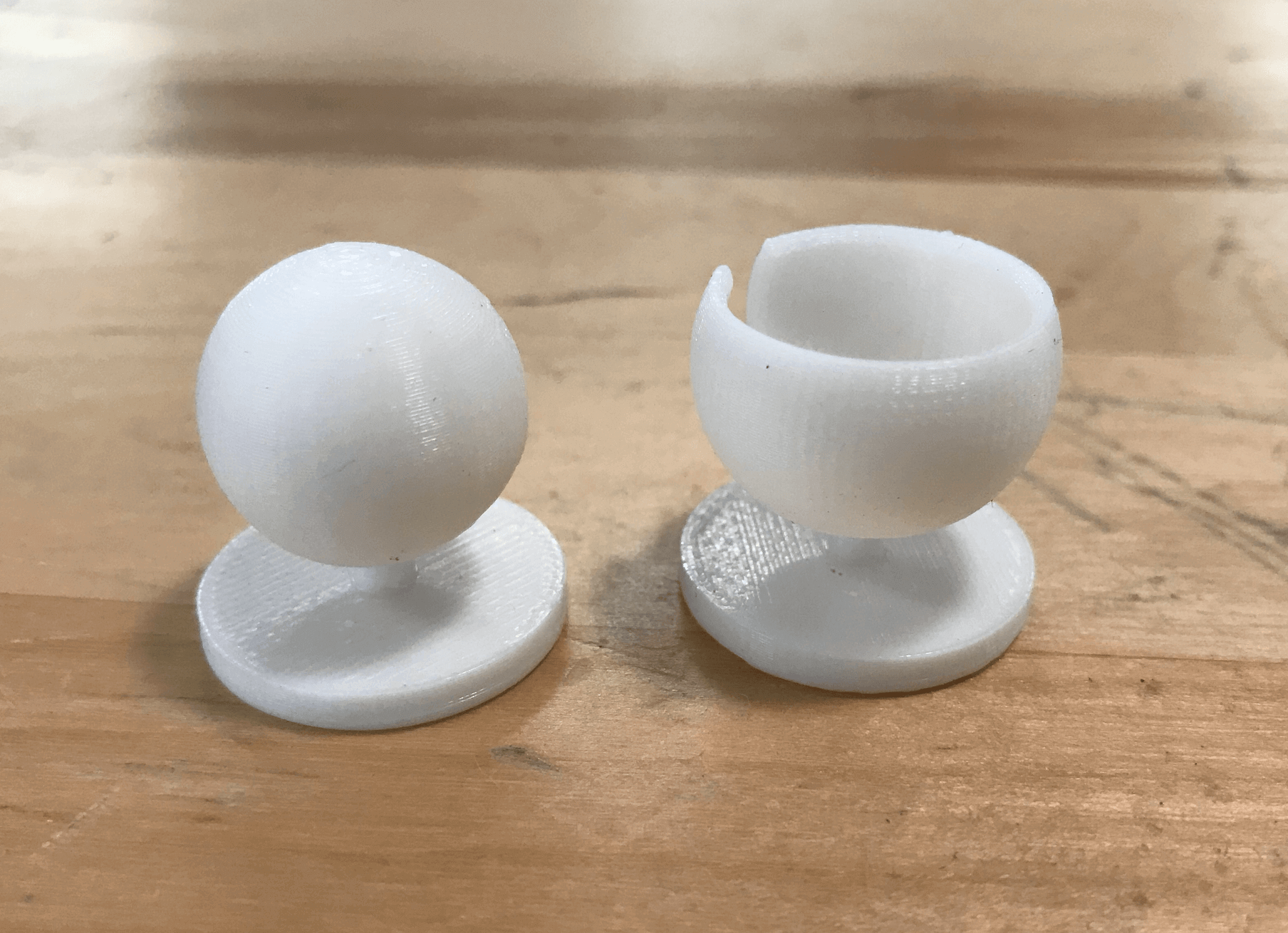
In order to disassemble the model, I had to use the snipper again because some parts were fused. I also needed to gently turn the two models left and right. From this experience, I learned that I should have set the tolerance a little larger. As a final touch, I used the sand paper to smooth out the surfaces, and this is how they looked after sanding. Overall, I was happy with this print, and I look forward to working on more projects that involve with design for manufacturing.
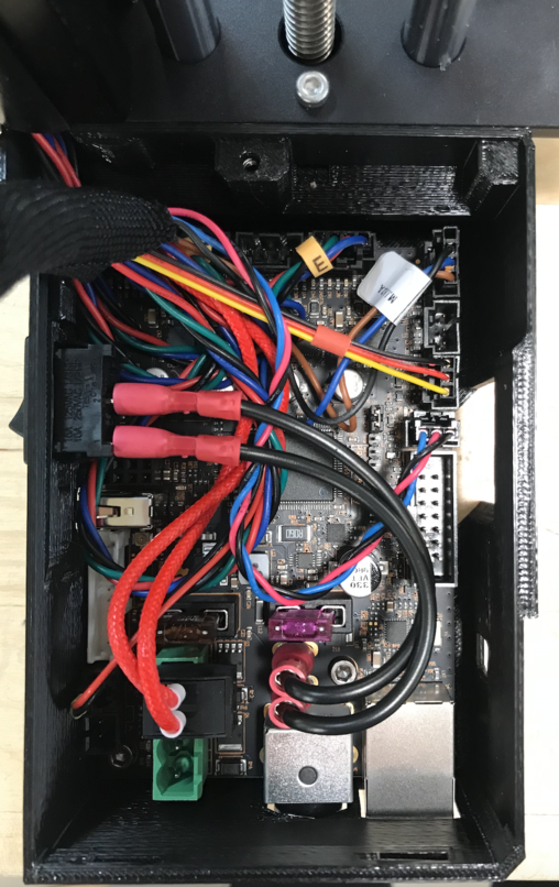
Assembling Prusa Mini Printers
Jun 25, 2021A few months ago, our lab manager Abhishek ordered two new Prusa mini 3D printer kits for the lab, since I wanted to learn more about 3D printing technology, I volunteered to help assemble the machines! While assembling the first machine, Vishal joined me to build a second machine. Here is a time-lapse video of us assembling the machines.
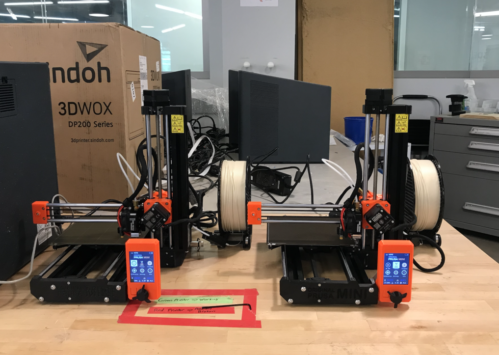
Here is the "before" image of the printers:
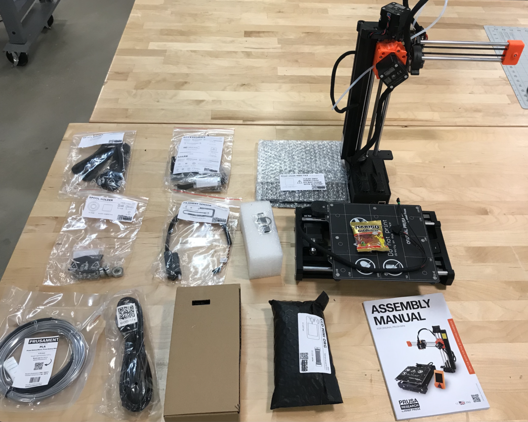
The plastic parts used on the 3D printers were printed by the same very machines.
Here is the "after" image of the printers. What I liked most was the systems integration because this is an area that I want to improve upon for my own project.
Learning SLA 3D Printing
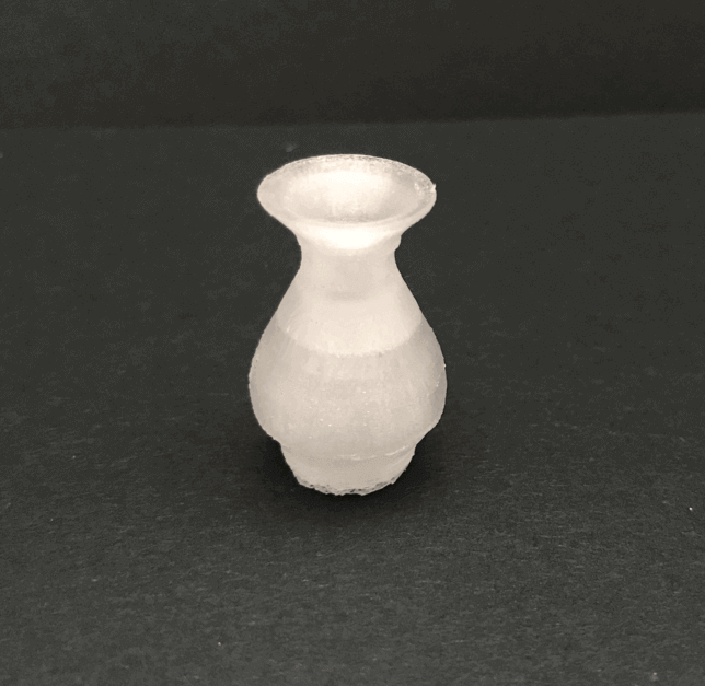
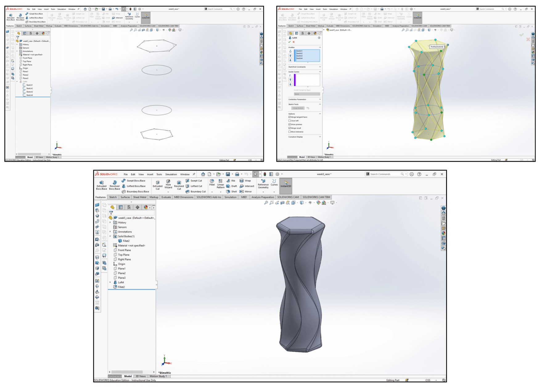
Jun 30, 2021During my Fab Academy, I have worked with mostly solid modeling, and I have always been wanting to improve my organic design skills through surface modeling. Over the weekend, I discovered this great YouTube tutorial, so I decided to follow the tutorial and modeled a sequence vase in SOLIDWORKS. Here is how the final design looked.
The vase design was realized by utilizing the following surface modeling tools: Revolved Surface, Lofted Surface, Knit Surface, Delete Face, Filled Surface, and Ruled Surface. I really like how surface modeling allowed me to have better control over curves. Here is a short video showing the modeling process of the vase:
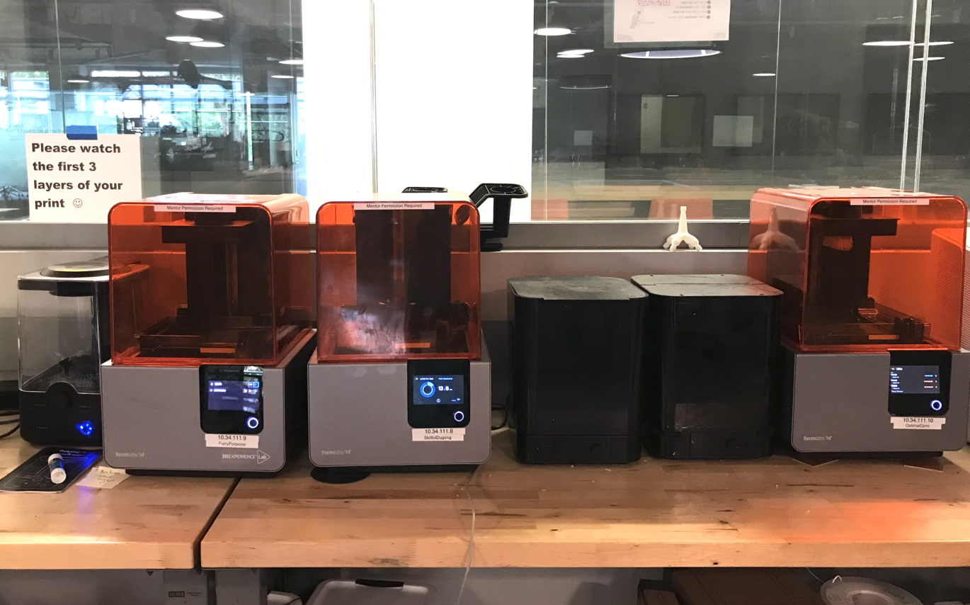
I have always fascinated about the Formlabs printers at the lab, and I wanted to seize the opporunity to learn SLA 3D printing. I also wanted to compare the performance between FDM priniting and SLA priniting.
I downloaded PreForm (the slicer for Formlabs printer) and loaded the model, and I immediately realized a problem: cupping issue. In this case, I found the printability menu on the right very helpful. To avoid the cupping issue, I must orient the vase at an angle and ensured that the enclosed face was facing up. I noticed that as the tilt angle increased, the estimated print time also increased, so I referred to Formlabs' documentation and set the tilt angle to 10-20°. I preferred using the full raft as my raft type, however I have reduced the touchpoint size from 0.6mm to 0.4mm. The following video shows how it looks. The estimated print time was 7 hours.
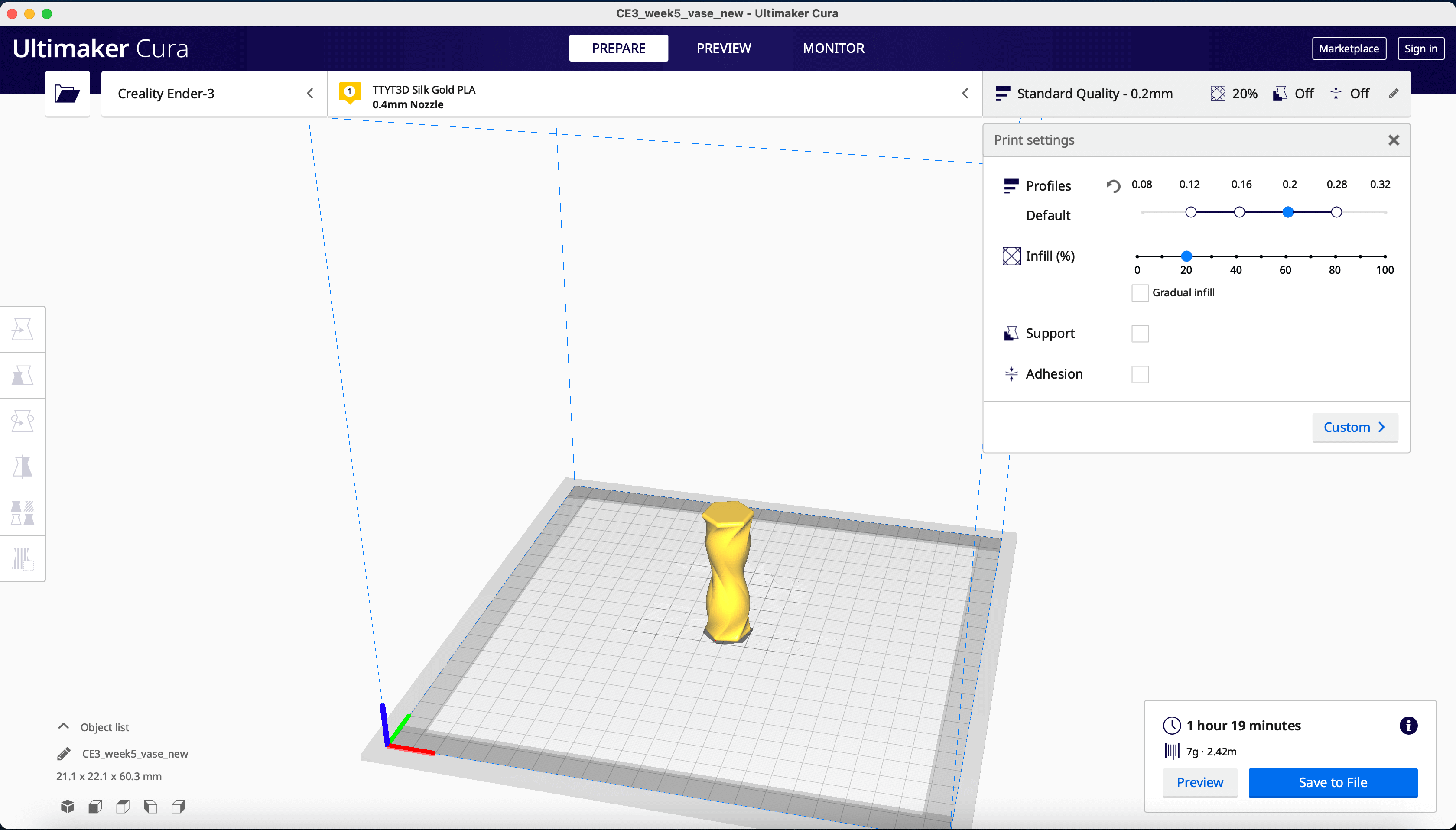
Next, I loaded the model to 3DWOX as I planned to use the Sindoh DP200 FDM 3D printer, and here is a short video showing the evolution of the print. As shown in the video, the model was lay flat with enclosed face down, and I didn't add any supports for this orientation. I also set the resolution as normal speed - normal quality. The estimated print time was 5.5 hours.
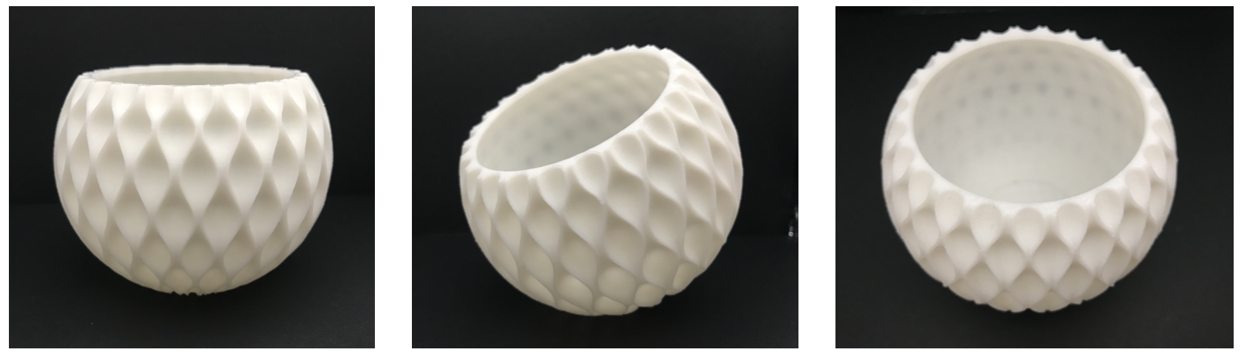
I realized that the opening for the original design was as large as my fist, and I was concerned whether I would be able to reach the supports inside the SLA prints, so I chose to scale the models by a factor of 1.2. As a result, the estimated SLA print time became 9.5 hours, while estimated FDM print time became 8 hours. Once I was happy with the model, I generated the Gcodes for both SLA and FDM prints, and was ready to print them at the lab.
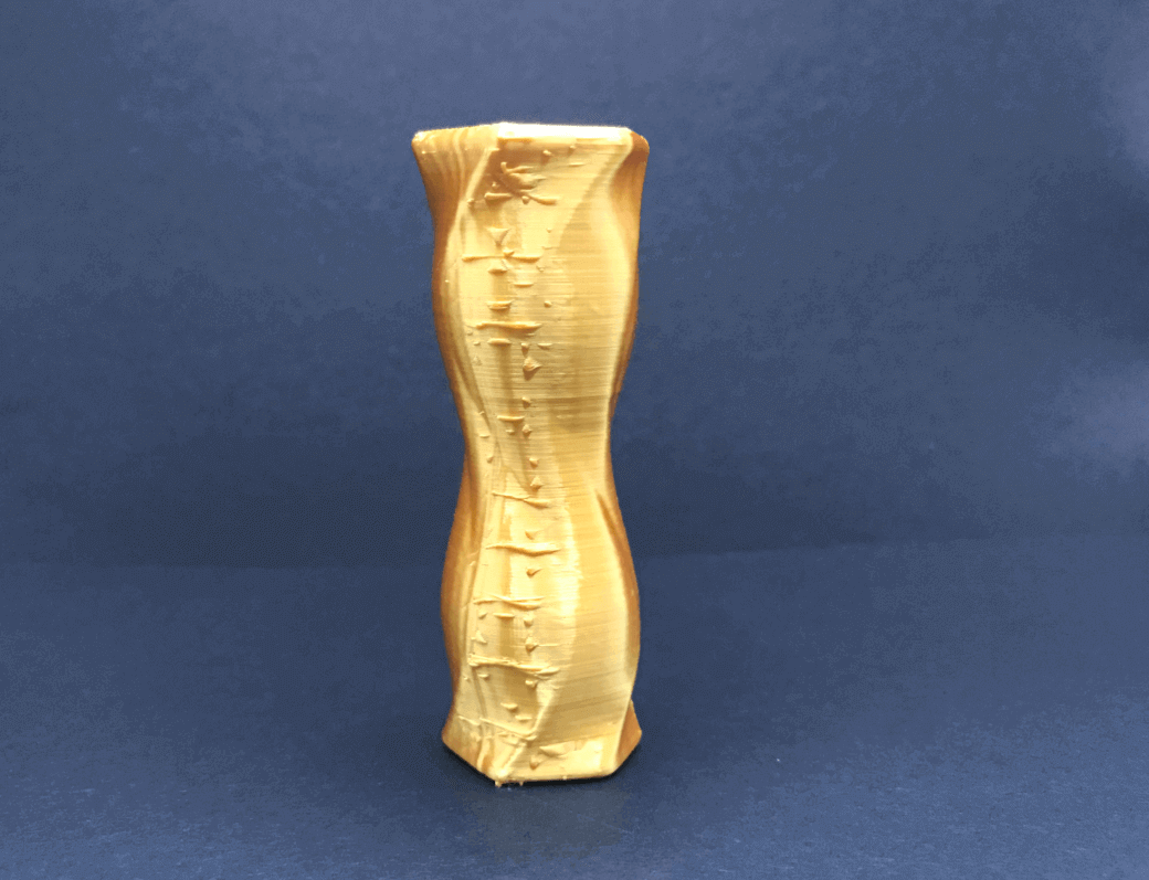
Here is how the FDM print looks. I was very happy with the result!
(Please stay tuned for the SLA print!)
3D Scanning
3D Scanning App: Qlone
During this week, I also had the chance to experiment with a 3D scanning app called Qlone. It was free to download and easy to use, and I think the result was quite satisfactory. Let's see how it works!
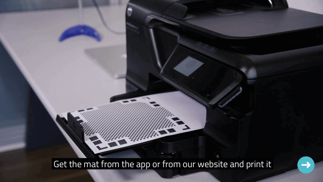
To begin, I needed to print out this mat on a non-glossy paper.
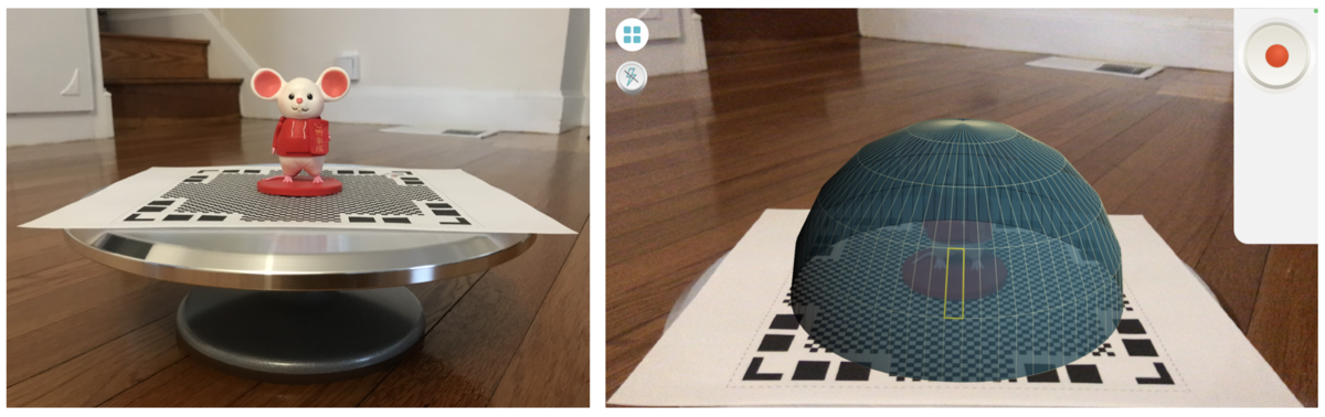
I have identified this adorable little mouse gifted by my sister as my 3D scanning object and placed it in the middle of the mat, once set up, an AR dome (green vs. red) would be there to guide the scanning process. To make things easier, I borrowed my mom's cake turning plate to rotate the mat for getting all the possible angles of the mouse during the process.
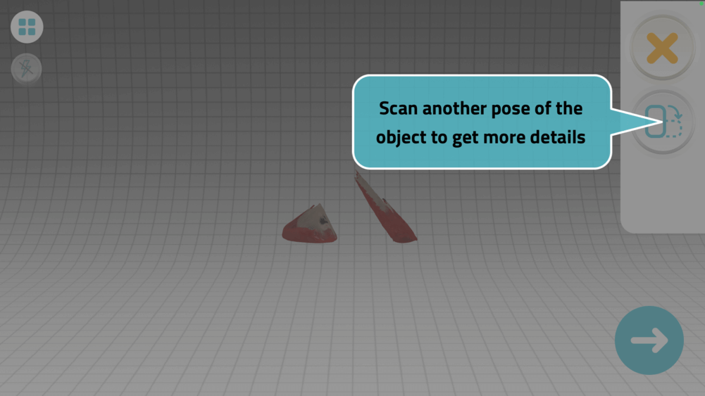
This was my first result - I was not able to get a good scan because I didn't scan enough of the green dome.
During the scanning process, I would be able to see a mesh cloud forming the shape. Once the scanning process was complete, the app would start to process the mesh cloud for the mouse.
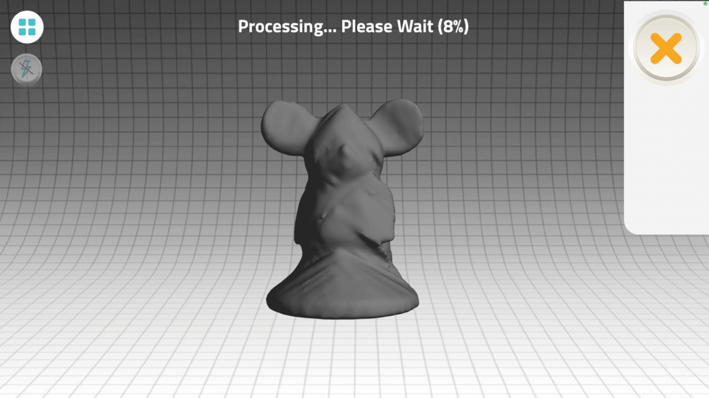
And this is the result. The scanned mouse even has colors!
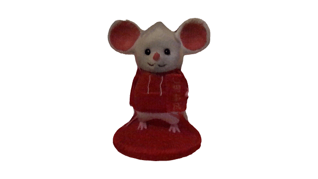
I have uploaded the pre-processed mouse and the post-processed mouse to SketchFab for better visualization of the results. The mouse ended up having a cone head, but this didn't cut its cuteness! There was some blemish on the back of its jacket, and I think that was resulant from me scanning over the red AR dome instead of the green AR dome. The little mouse was not perfect, but it was certainly still recognizable, so I would call this was a successful scan.
At the end, I played with the AR mode and had the chance to see my little mouse dance 😆!
Files
Please find below the files that I made for this assignment.
- 3D Printing:
- Vase
- STL file (File name: week5_vase_pattern.stl)
- Finger Massager
- Ball-and-Socket Joint
- Sequence Vase
- SOLIDWORKS and STL models
- .form file (for Formlabs SLA 3D Printers)
- 3D Scanning:
- Mouse
- STL file (File name: 3d-scanned-mouse.stl)