
This work is licensed under a Creative Commons Attribution-NonCommercial-ShareAlike 4.0 International License
Week 15: Interface and Application Programming
May 10, 2021Summary
This week's assignments
- Group assignment:
- Compare as many tool options as possible and document your work
- Individual assignment:
- Write an application that interfaces a user with an input and/or output device that you made:
- Document your process ✔
- Explain the UI that you made and how you did it ✔
- Outline problems and how you fixed them ✔
- Include original code (or a screenshot of the app code if that's not possible) ✔
- Include a ‘hero shot/video’ of your application running with your board ✔
Resources Used
- Software: Arduino IDE, Processing
Skills Gained
- Application Interface Programming
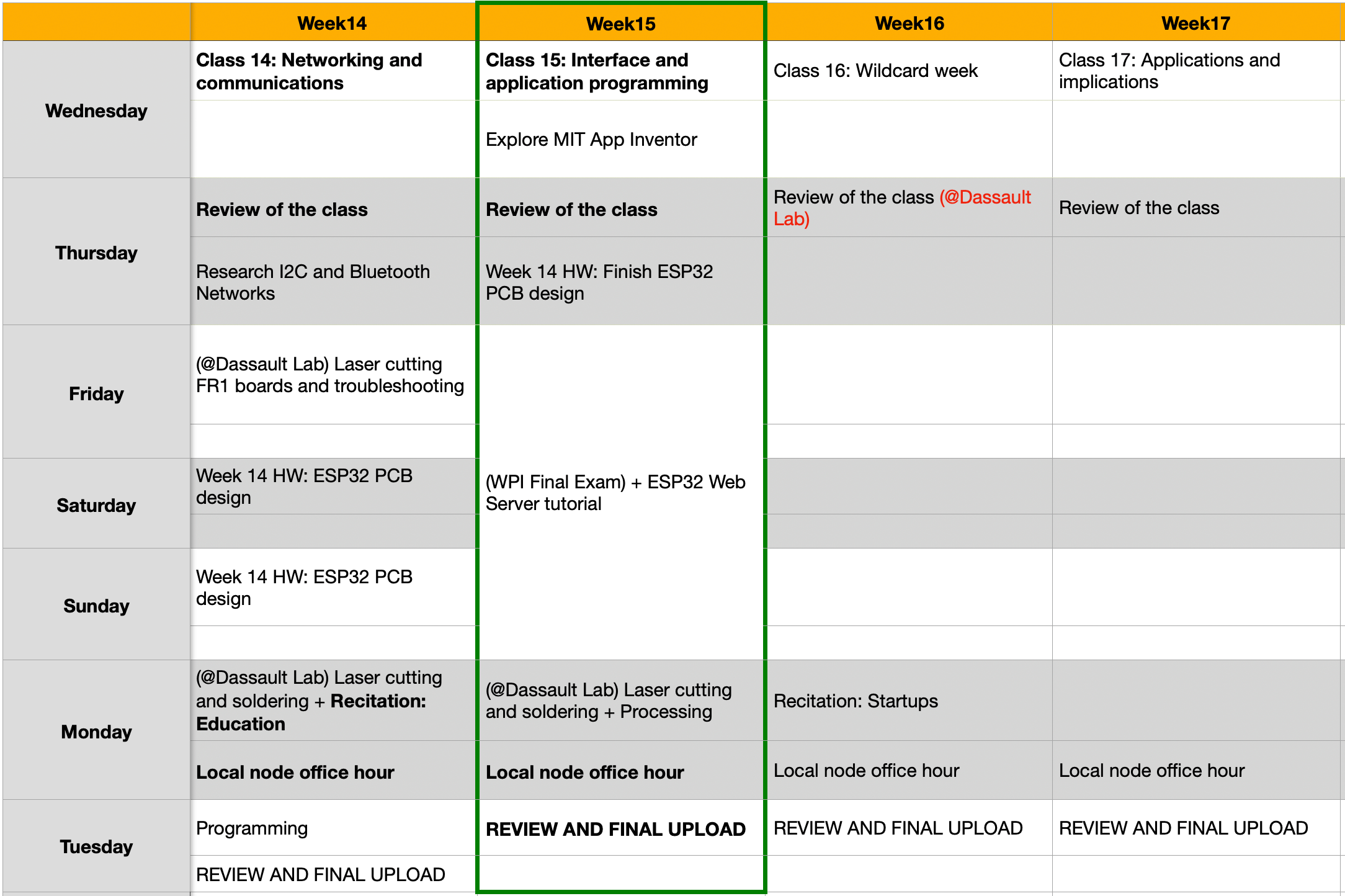
My Weekly Schedule
Processing
Part 1: Turning on and off the LED
During the Global Lecture, Neil introduced to us various tools for creating user interfaces. Particularly, I was interested in learning an open source tool called Processing. I learned that this is a language for coding in the cotext of visual arts. In this case, I could get the visual representation of the serial readings I get in Arduino for my boards.
Since I was new to Processing, I decided to look for tutorials that are related to the I/O devices of my board. After downloading Processing, I got started. I found this tutorial for visualizing serial monitor readings with Processing.
Since I don't have my ESP32 board yet, I decided to start with the ATtiny1614 board that I made in the previous week. In my board, I had a power indication LED, so I decided to follow this tutorial step-by-step, and tested it on my board.
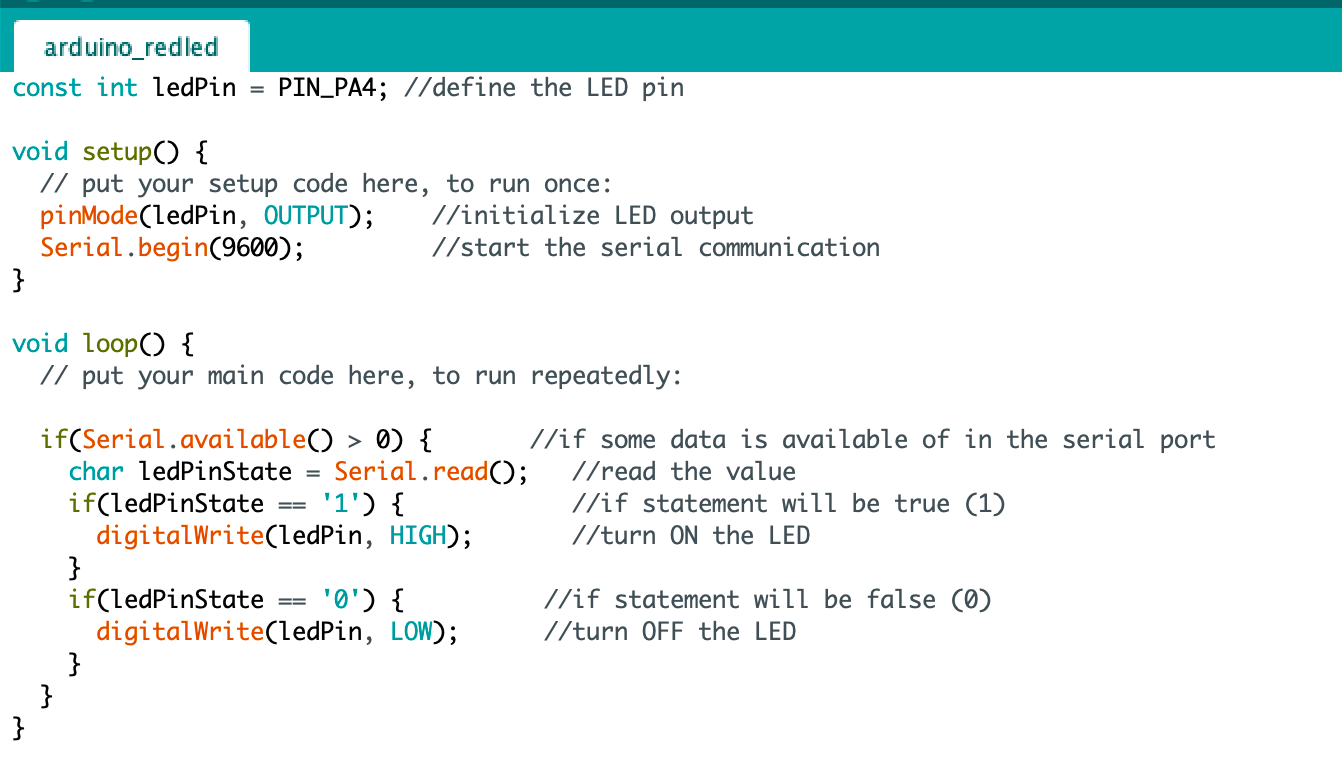
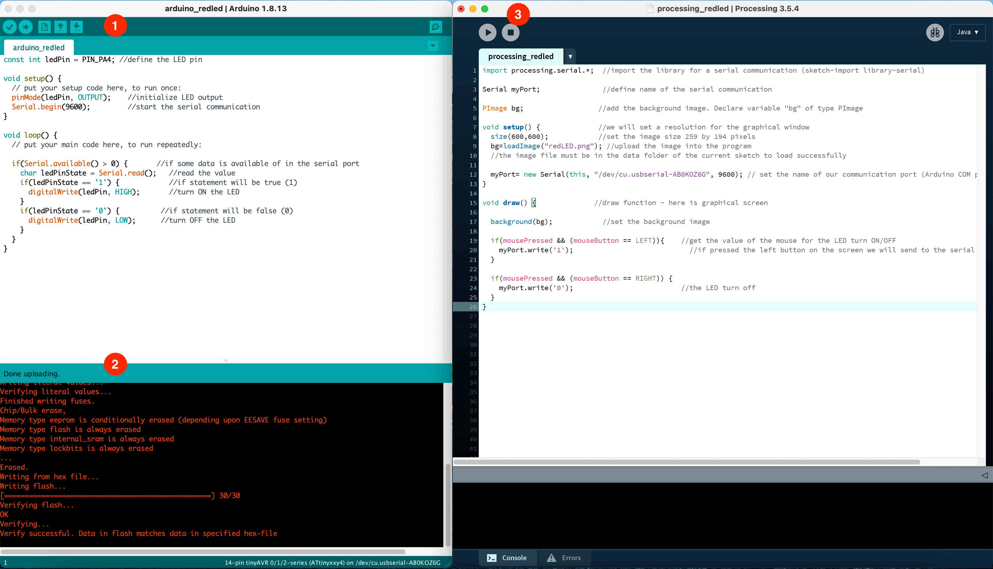
To begin, I created the Arduino sketch as shown below. In the pre-setup stage, I declared the LED pin on my ATtiny1614 board, PA4. Since Serial is the "ambassador" between Arduino and Processing, I also made sure to use Serial.begin in the void setup() step, I used baudrate of 9600. In the void loop() step, I used 1 or 0 as the condition to determine whether the LED would be on or off.
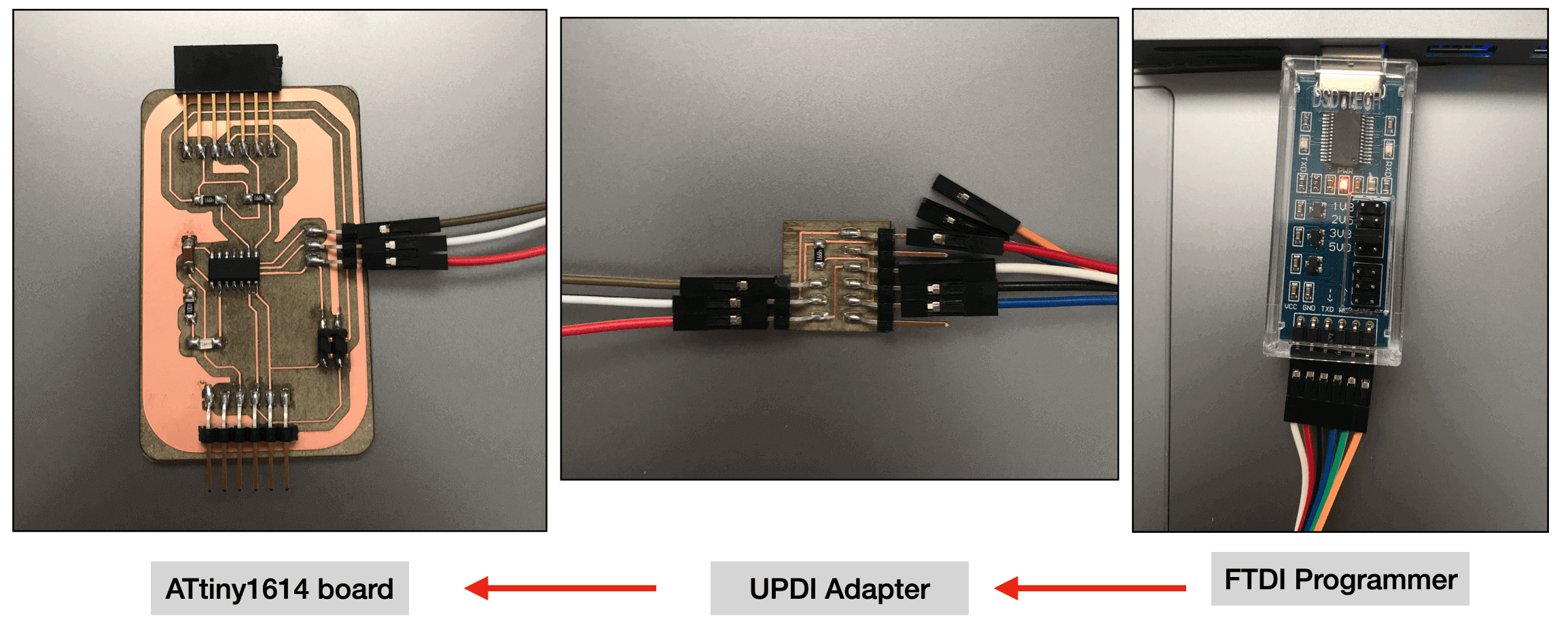
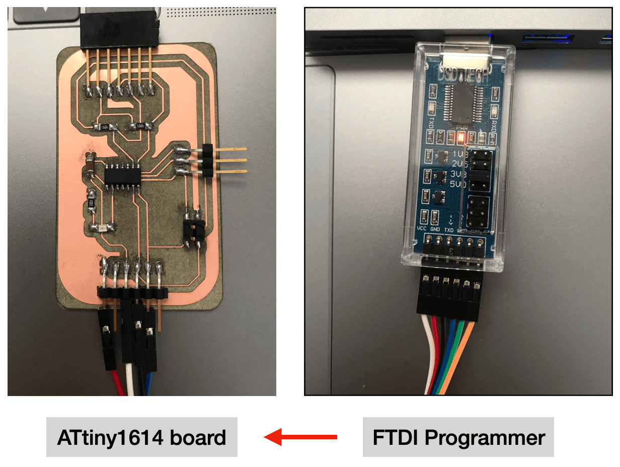
Next, I was ready to test the sketch. To begin, I connected my board to the FTDI programmer via the UPDI adapter, this is the same set up I used for testing the LSM6DS33 Accelerometer/Gyro module in the previous week.
I made sure to select the correct board, port and programmer
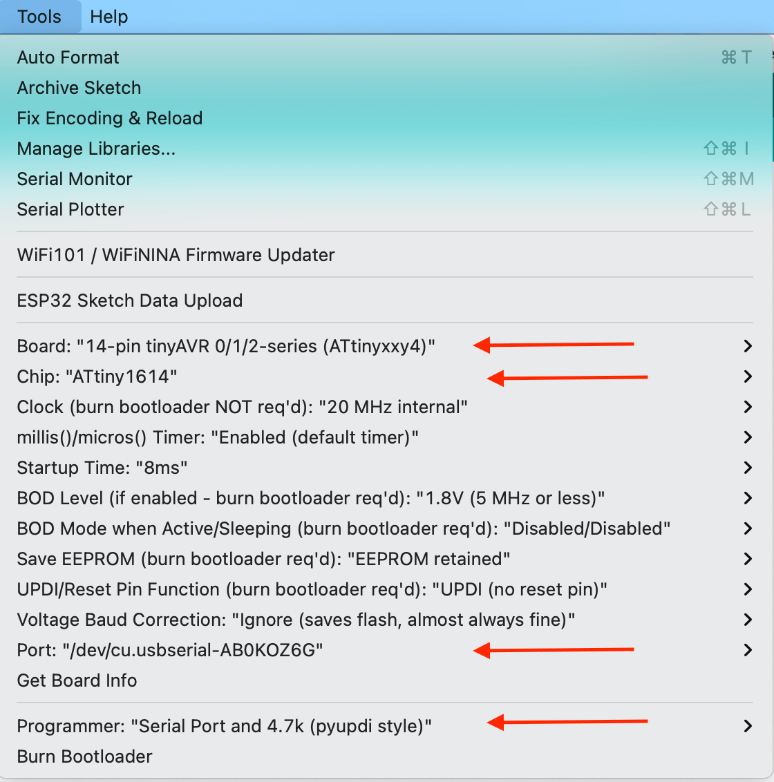
And clicked "upload":
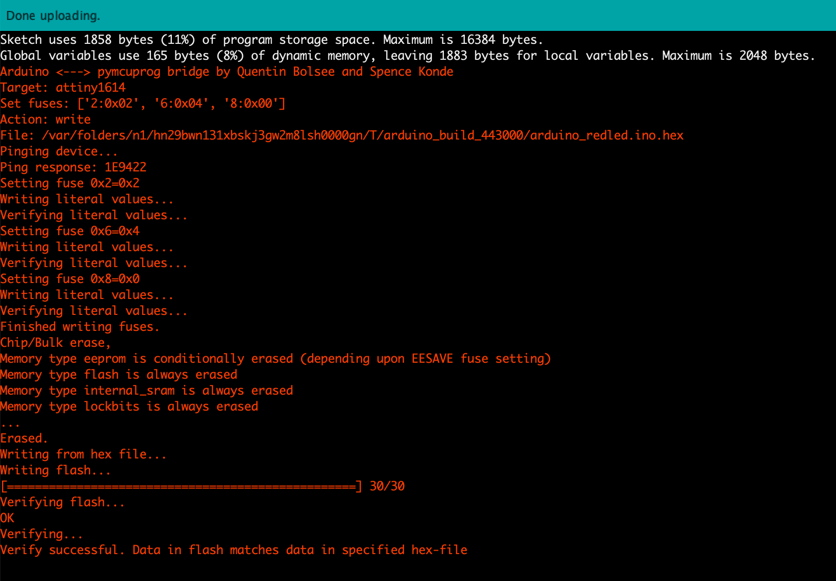
After verifying successful upload, I removed the UPDI adapter from the connection, and changed my wiring set up to be like this:
I opend "Serial monitor" in Arduino IDE. After making sure the baudrate was "9600", I started typing "1" and "0". Here is a short video featuring the board and its LED. As shown in the video, when I typed "1", the LED was on, when I typed "0", the LED was off - this verified that my sketch worked!
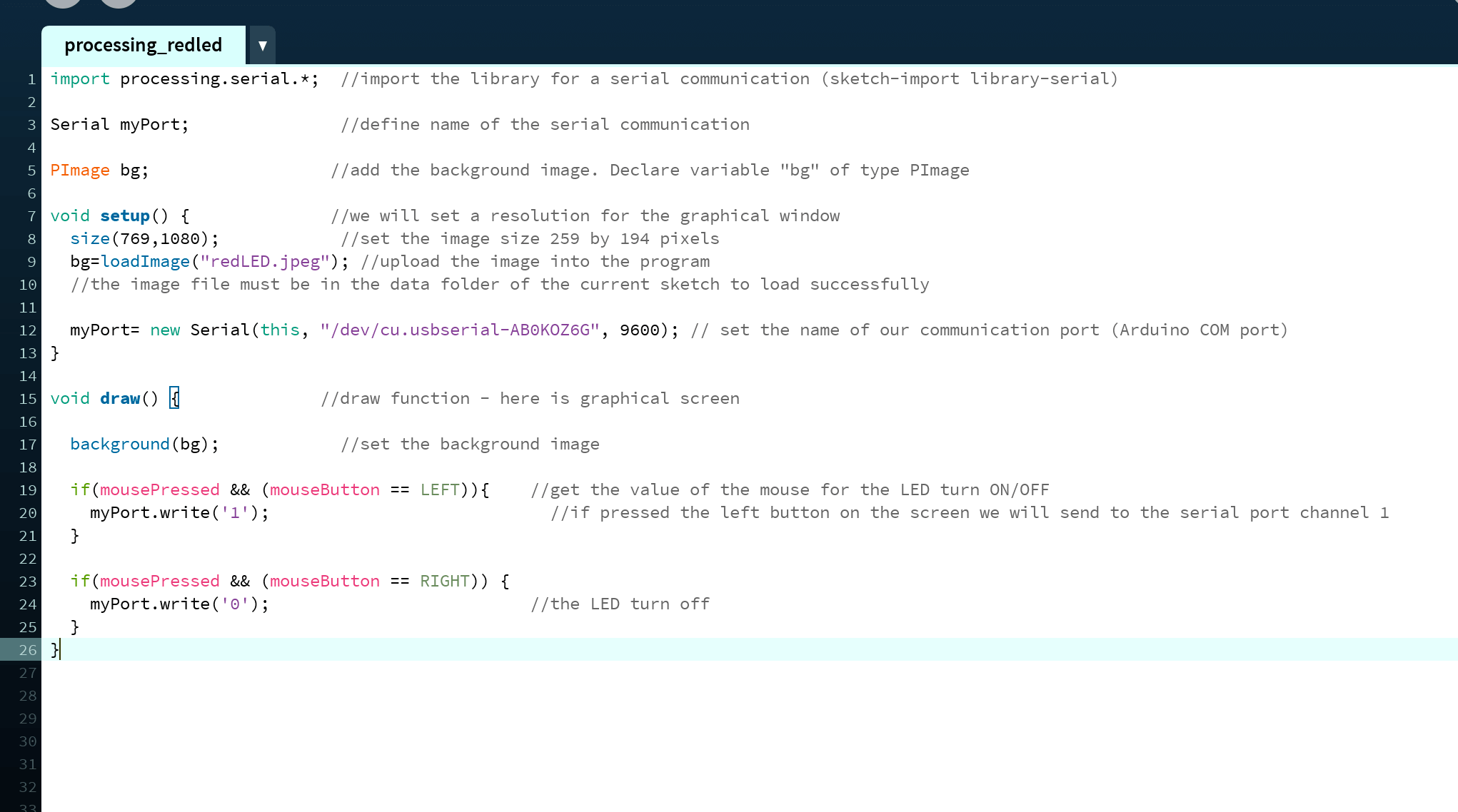
Next, I followed the tutorial to create the Processing sketch. In order to work with serial, I first imported the library (processing.serial.*) for a serial communication. I had created a directory called "data" in the same location of the Processing sketch. In void setup(), I defined the variables (i.e. size, name) for the background image that I would be using; I also made sure the Processing sketch have the same serial port and baudrate as the Arduino sketch. The name of the serial port can be retrieved from Arduino IDE (Tools > Port). Different from Arduino, Processing used void draw() instead of void loop(). The idea of the program was that, when left clicking an image, the LED would turn on, when right clicking the image, the LED would turn off.
The last part would be integration and testing. First, I uploaded the Arduino sketch using FTDI + UPDI + my board. Once verifying successful upload, I connected my board only to the FTDI programmer, and click the run button in the Processing, this worked the same as the "serial monitor / serial plotter" in Arduino IDE.
Here is a short video featuring the whole process. As shown in the video, the LED turned on as a response to the left click, and turn off as a response to the right click.
Part 2: Playing with the Accelerometer/Gyro Module
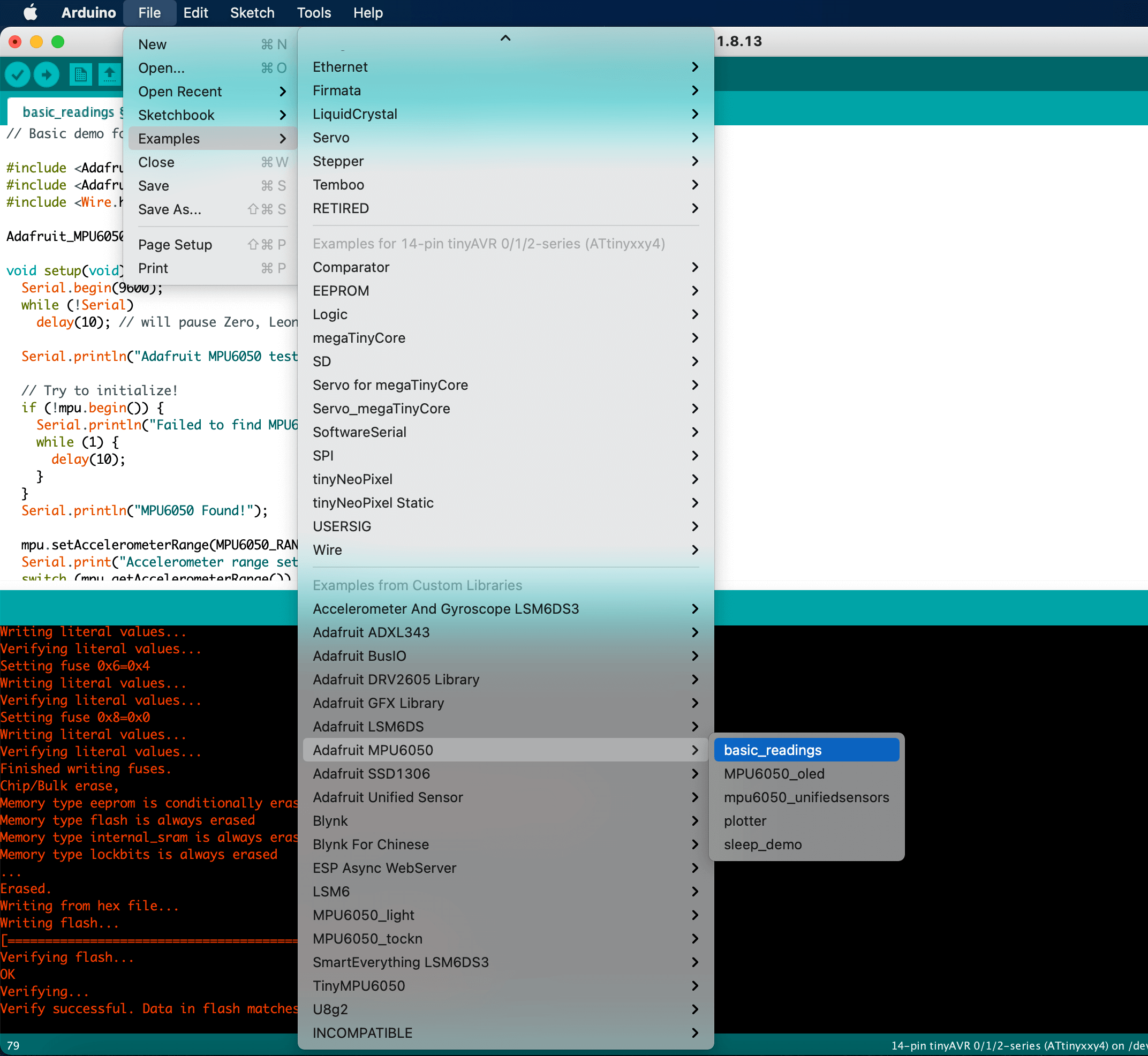
For this exercise, I wanted to work with the MPU6050 accelerometer/gyroscope module. To begin, I used Adafruit's MPU6050 example code "basic reading" as the starting block for Arduino sketch. To simplify my task, I then removed the information for the acclerometer and the gyro and left only the acceleration. I also referred to this rotation tutorial by Processing when building my Processing sketch.
Here is an image of the Arduino sketch that I chose to work with:
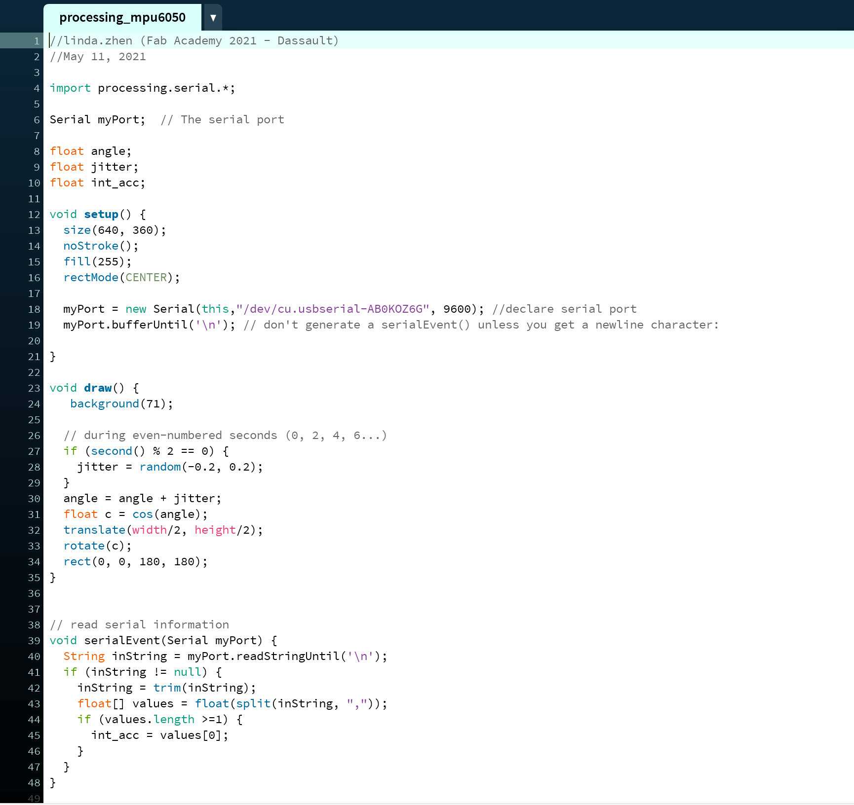
And here is the what the Processing sketch looked like - I borrowed the content from the rotation tutorial in the void setup() and void draw() steps.
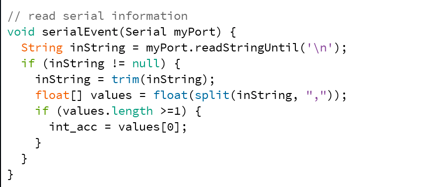
I learned from Adrián's documentation to have the following instructions for serial communication between our board and Processing must be added at the end of the sketch.
And this is a short video featuring the rotating square and the MPU6050:
Files
Please find below the files that I made for this assignment.
- Processing: