10. Input devices
Group Work
For this week’s group work assignment, I helped my group complete the week by learning how to use the multimeter myself as well as testing multiple different devices with an oscilloscope. I was able to see the different signals between analog and digital devices. Group site found here
Task
The assignment for this week is to measure something: add a sensor to a microcontroller board that you have designed and read it. In order to complete this assignment I am going to use a motion sensor for my RC car that will detect when it is nearning a wall and slow the motors down allowing for a change in direction.
Eagle design
For this week’s assignment I first decided what sensor I would like to use for my input devices board. I decided to create a board that I could use in my final project which as a doppler radar sensor for an RC car. I first watched the lecture where Neil demonstrated the functionality of the sensor and decided that it would be neat to incorporate a function in the RC car where if it is fastly approaching a wall it will decrease speed allowing for course readjustment. In order to start my eagle schematic I used neils schematic as a reference for how I was going to create my board. I used the fab.new library to get the components needed for my schematic.
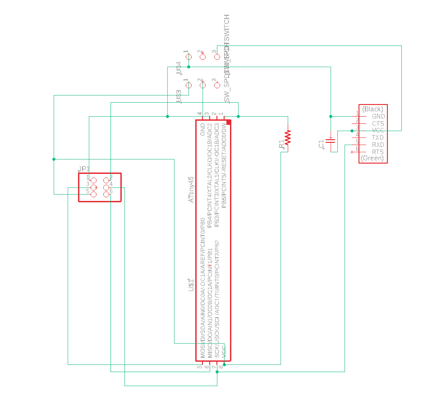
Above is the initial schematic for the board I am creating. It features FTDI headers as well as a Attiny45 processor and Headers to connect the RCWL-0516 Doppler Radar chip that I will be using to measure acceleration towards a wall with. The board also features 1 capacitor valued at 1uf and 1 resistor valued at 10k ohm. I used the route function to connect each pin to the desired pin on another component. Once this process was completed switched the board from schematic to .brd to begin routing the traces that would be milled.
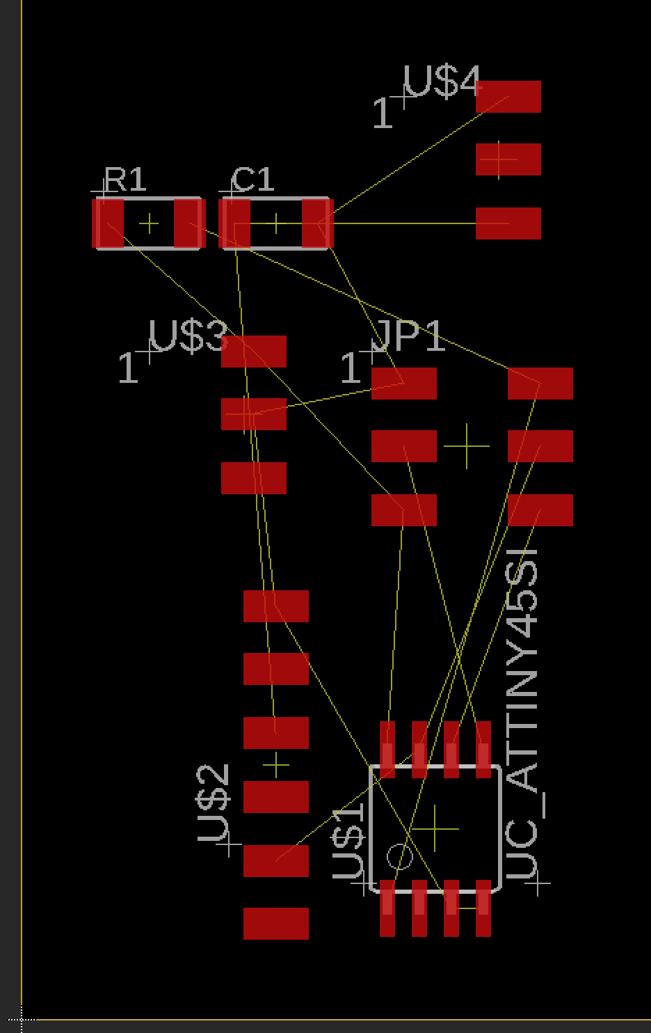
Above is a photo as soon as the schematic was transformed from schematic to board. None of the traces have been connected as indicated by the tiny lines connecting the components and they are all in disarray. I had to rotate and move around components in order to generate the cleanest schematic I could that would provide the least amount of troubles while soldering.
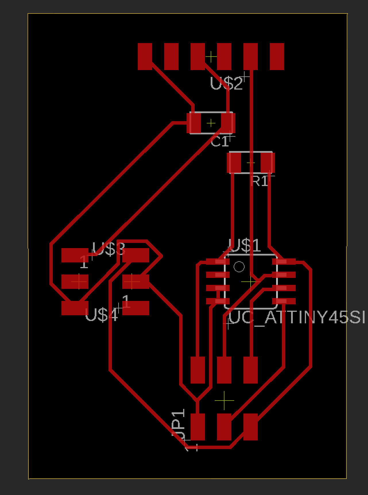
Above is a photo after I manually routed each trace and organized the components properly. This allowed for a very neat looking schematic that would be easy to mill and solder. I had to change the trace width from 6mm to 16mm as the bit on the CNC mill was tearing up the traces as it attempted to mill. Once I had set the outline size of the PCB I milled it out on the CNC machine.
Eagle Redesign
After numerous errors with my input board and the use of the Attiny45 I re-designed my eagle schematic centered around the use of the new Attiny412 processor. In order to correctly design my schematic I had to reference the pinout to connect each pin of the processor correctly. I had to connect the TXD and RXD pins correctly for serial sending and receiving for my board to be able to print the data received form the sonar board. I also had to shift around the MOSI and MISO pins to their corresponding place on the ATtiny1614 since they go under a different name. I took this time to clean up the new schematic as well to eliminate the possibility of unwanted errors that I was experiencing earlier.
For my new schematic I used the same components as my old schematic except removed the resistor and ISP programmer and switched out the Attiny45 for the Tiny1614. This 1614 saw more success among my classmates and I had become hardstuck with the 45 after 3 separate board attempts. I could not find the ATtiny1614 in the Fab library so I found it on a website called SnapEDA and downloaded “Symbol” and “Footprint”. You can find it here. After connecting my schematic properly I converted it to a .brd file and routed all the traces in similar fashion to the schematic above. I neatly organized the traces and made their width wider. Once this was completed I exported the file to mill.
New shcematic
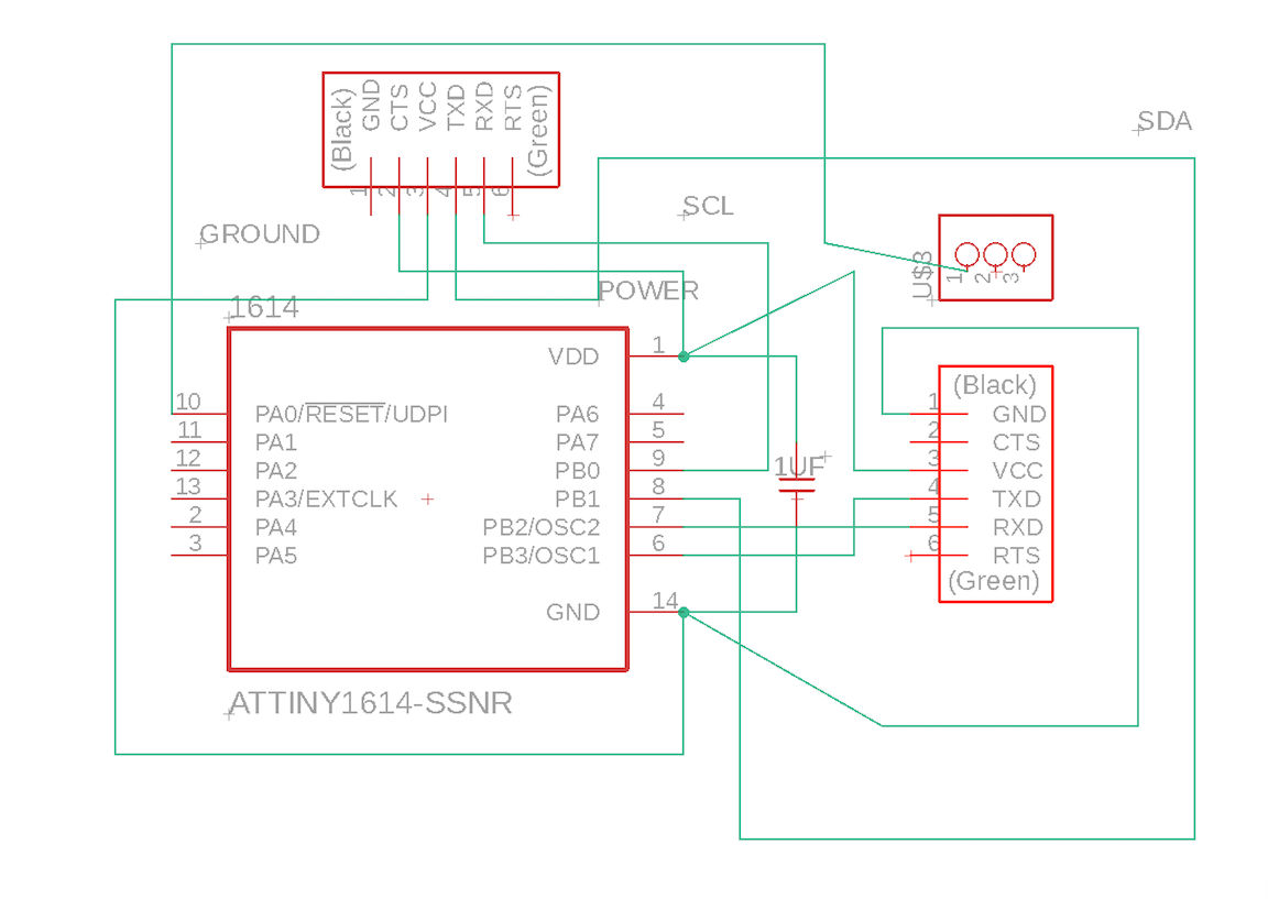
Above is my new schematic that ended up working and displaying the serial data from my sensor. I had to change my original schematic to incorporate the 1614 processor. In order to complete this schematic I first had to research the pinnout. Afterwards I had to correctly connect each of the pins for the UPDI pins and pins to connect my sensor breakout board. I then converted my schematic to board and connect the traces before I could export and mill
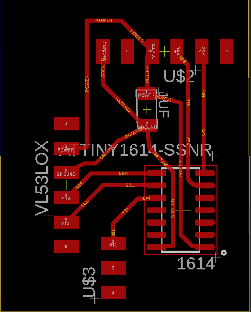
The image above is the board file for the board I was milling. When I first converted it from schematic to board I had to orient my components so that the traces would be as neat and easy to rout as possible. Then I used the auto router tool just to see if I liked what it would generate. Once it finished routing I was satisfied with the traces but I changed the size for 6mm to 16mm. After everything was completed and I dragged the outline in, I exported the file to mill.
Milling process
In order to begin the milling process I first had to download my board files and open them on the bantam tools software which is what I used to mill out the board on our CNC’s. Once importing the board I positioned it on the bed where it would save the most space on the PCB allowing for others to cut. I then used nitto tape to fasten the PCB material to the bed of the CNC to prevent movement. Once this was completed, I clipped the conductivity clip to the material and inserterted the engraving bit (.005mm) into the spindle. I had to select the tool and locate it. Once this was done I propped the material thickness and began milling the traces of the board. I repeated this same process with a 1/32 end mill bit but instead of engraving traces I cut out the board.
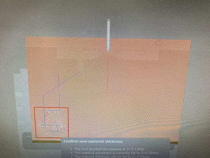
Above is the mill file positioned on the bed of the PCB material. This step was right before I located the first tool (.005 engraving bit) to mill out the traces of my board.
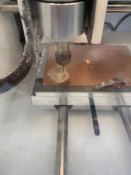
This is an image of the CNC engraving the traces on the board. After this is complete I switch the bits to the 1/32 bit to cut the board out.
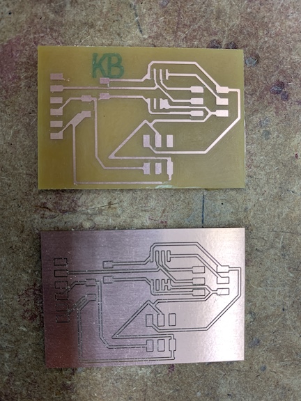
This is an image of two different board styles I milled. The one where it is only copper traces is done by changing the trace clearance to a number such as 20 that will use the 1/32 bit to mill off all excess copper except traces created by .005 bit. I thought this design looked very neat and had never done it before but ultimately stuck to the bottom board which completed the regular way of using the .005 to do the traces and 1/32 to cut the board out.
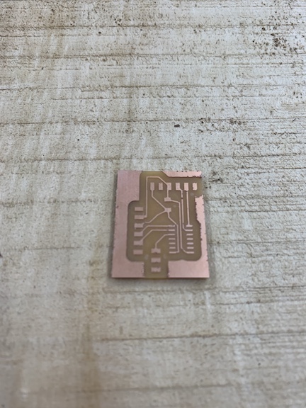
Above is the finished milling process. I set the trace clearance to 2mm to give me a little room to solder to prevent shorts onto the board. I used the 1/32 bit to mill the outline of the board and the excess copper that was milled away and used an engraving bit to mill out the pads. I followed the same process as documented above and used the new schematic. I cleaned the finished product up with an exacto blade and washed it off before soldering.
Soldering
The soldering process for this board was rather quick. I only had to solder 3 sets of surface mount headers along with the attiny45 processor and 1 resistor and 1 capacitor. I soldered two boards throughout this week, the first board encountered a small bridge that resulted in a torn trace but the second board was completed with no problems. I used the lab’s soldering iron along with flux to complete the solder for this board. Due to the shape of my sensor it will be connected via jumper cables to the headers on the top side of the board.
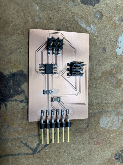
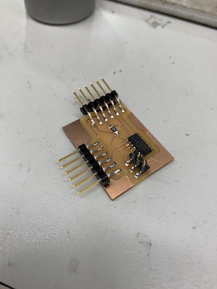
The image above shows each component soldered except for the sensor itself as I had to order it on amazon and the delivery is scheduled for tuesday. Once the sensor arrives I will connect it to the board and program it. I have soldered in the photo all the headers, the chip, the resistor, and capacitors all without problems. I later relized this board was shorted out and re-milled a new board.
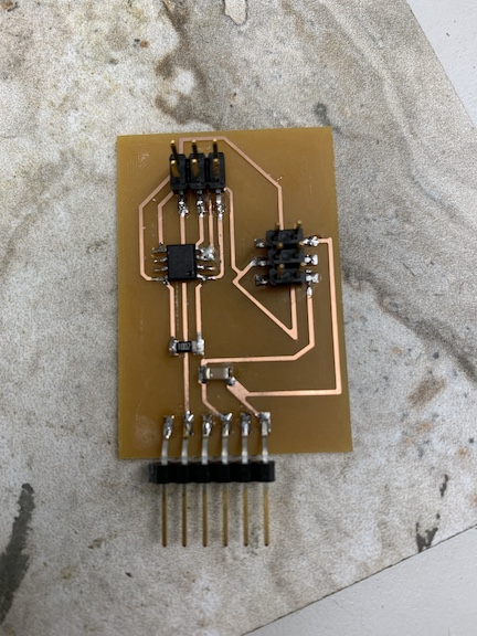
Above is the new board I milled after the unresolved short in my previous board. I used the technique of removing the copper that I failed at earlier to prevent the possibility of more shorts. I soldered this board rather quickly and used a multimeter to test the entire board for shorts when connected to a programmer via corresponding pins as well as ensuring 5 volts was flowing through the processor. I will now begin to upload a code to verify that the board works before attaching the sensor.
The image above is the completed soldered board for input week. I had the 1614 processor in the center of the board. I soldered this component first to ensure no tight spaces would have to be soldered later on. I used flux paste to ensure that I could easily remove bridges if they form. I did not encounter any errors on this board while soldering. I also had to solder a 1uf capacitor between the power and ground to smooth out current. I lastly soldered UPDI pins and pins to connect my breakout board.
Coding
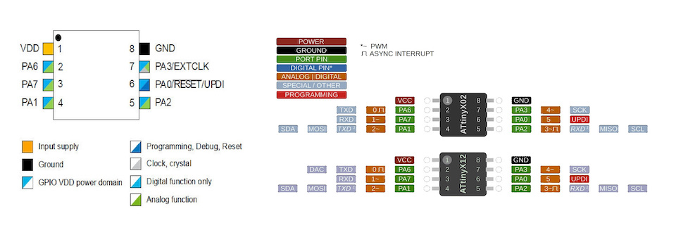
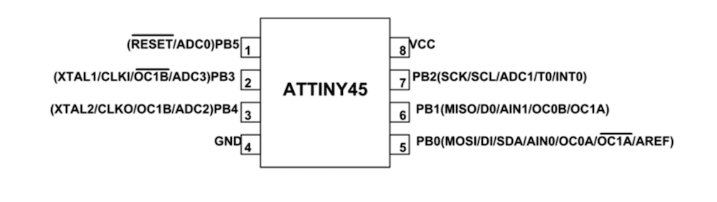
Before I could begin coding the board I created for this week’s inputs assignment I first had to ensure that I was connecting each pin correctly. In order to determine this I referenced the Attiny45 datasheet and tested my traces with a multimeter. This pinout below shows each pin of the 45 chip and aided me in testing my connections and figuring out which pin was what in the orientation on my board.
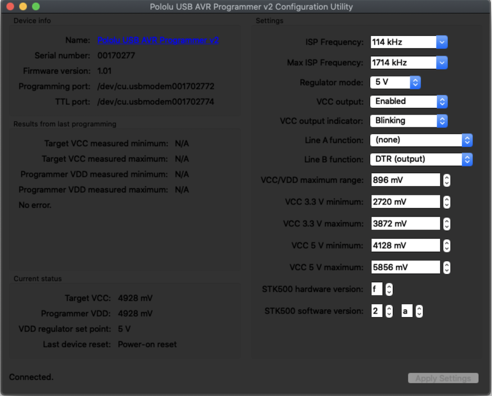
In order to code the Attiny45 I first had to install the Pololu AVR programmer drivers so that I could set the ISP programmer with Arduino. Once I had this installed I could set whether I wanted the ISP pins to be the power as well as what the correct comp port for programming my board would be. Once I had all this information I could configure the chip in arduino and upload a working code to it.
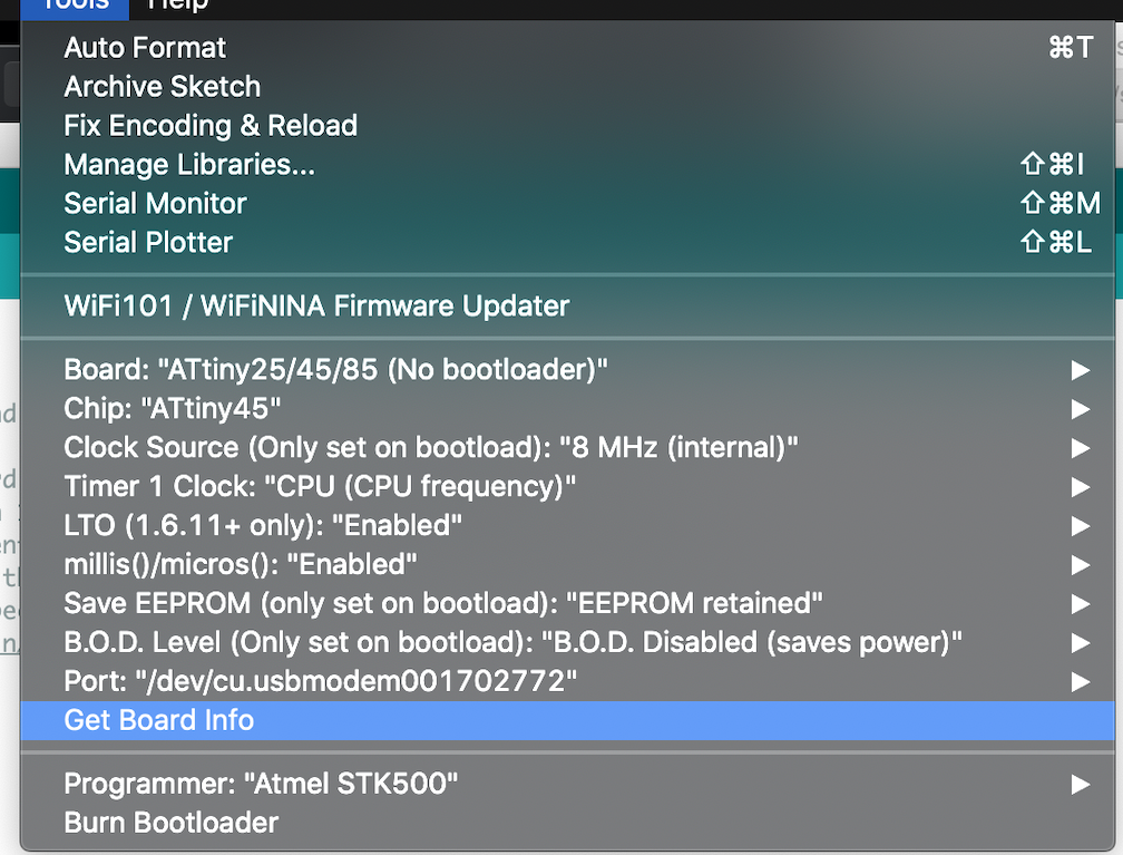
Above is an image of the settings I had to change within arduino to be able to upload code to the board I created using the programmer. I had to download a new ATtiny library to access the 45 chip. Once this was completed I set the chip as the 45 set the com port and set the programmer.
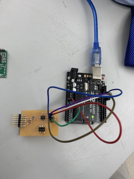
Above is the connected input board to the arduino uno to upload a code to it. I first had to upload Arduino as ISP to the arduino. Then I had to reference the pinout of the Attiny45 and Arduino Uno ISP to connect each jumper cable properly. Afterwards I uploaded code to my board. Unfortunatly this board did not work even after repeated trouble shooting so I am re-designing my schematic around an Atiny1614 processor.
Tests
Once I had my input sensor that I was using for my project I first tested Its functionality by directly connecting it to an arduino. I uploaded a code to the arduino to were each time the sensor detected something it would print motion detected within the serial monitor and illuminate an LED that I connected to the arduino. This was to test that my sensor would even work with the Attiny1614 board I was creating.
As you can see in the youtube video above, each time the microwave waves from the sonar board detect an object in its path the light illuminates and motion detected is printed to the serial monitor. After a little delay the light turns back off where the process can be repeated.
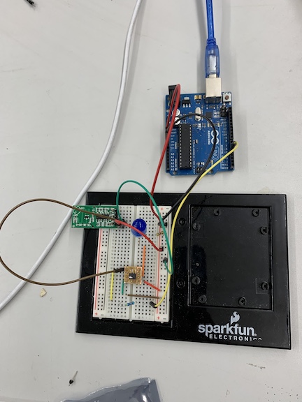
After testing my sensor’s functionality I moved on to testing it with a small ATtiny412 board and used a breadboard for all other components such as resistors, LED’s, and my sensor. I powered the breadboard and uploaded code via an Arduino UNO programmed with Jtag2UPDI. After this was completed I referenced a 412 pinout to see which pins to connect my sensor into and which pins to connect arduino jumpers into. I connected the power and ground of the sensor into the ground and VCC of the 412. I then connected the sensor’s out (data) pin into the 412 pin 3 and the LED into pin 2. I also had to connect the TXD and RXD (transmitting and receiving) into the 412 and then into their reciprocating pins on the Arduino. Note while uploading programs from the arduino these two jumpers can not be plugged in. These cables allow for the sensor to transmit serial data to the monitor. I attempted to test this with a code but have not yet had success. The LED will not light up which is an issue with the serial monitor not alerting that motion has been detected.
After repeated errors with the serial monitor on the ATtiny412 chip I decided to use a simple Attiny1614 chip connected to a breadboard to test if this chip worked better. My groupmates had success with the serial print function of this chip so I thought after repeated failure this processor would work better. I first constructed the circuit on a breadboard then once it worked would mill a board myself
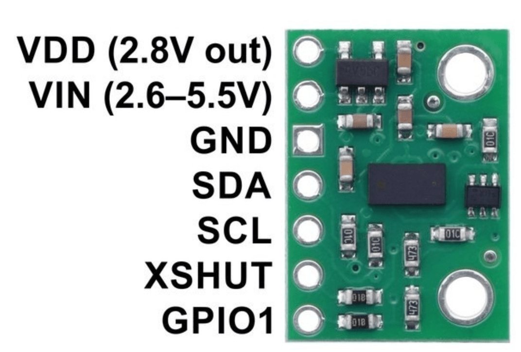
Due to the fact that the previous sensor I was attempting to use was not working properly I changed to a time of flight sensor. This sensor worked in a very similar fashion to the Doppler radar sensor I was using earlier. To begin using the sensor I first tested its functionality by connecting it directly to an arduino. I had to connect the power, ground, SDA, and SCL pins to the arduino in order to be able to upload code and print serial data. Once I had this correctly set I uploaded the example code form Pololu and ensured I had the correct Baud rate of 115200 for the sensor. Below is an image of the pin out for the time of flight sensor
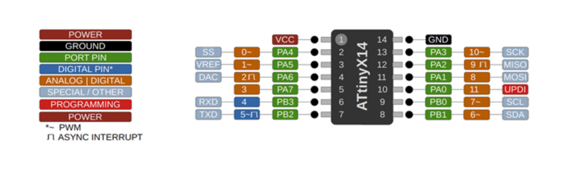
While coding the new ATtiny1614 processor above is the pinnout I referenced for coding the sensor. This sensor does not differ too much from the ATiny412 sensor but has more pins on it. In my eagle schematic I replaced the previous 412 and reconnected the pins before milling an input board. I had to download a library in order to be able to import the component into my eagle schematic.
Below is a video of the repeated process that I did with the 412 where I connect the senor to an Arduino and upload a code to ensure it works. As detailed in the video as my hand gets closer to the sensor the numbers printed in the serial monitor decrease. This proves that my distance sensor is registering and the code works as well.
Below is a video of the similar process from the ATtiny412 except with the Tiny1614. I followed the pinout for both the sensor and the processor to connect everything properly to the breadboard. After this was completed I connected the breadboard to an Arduino programmed with Jtag Update. I then changed the board to the 1614 chip in the tools menu of Arduino in order to upload the code to my processor. As displayed by the video you can see that the code did in fact upload and when I move my hand closer the numbers get smaller indicating that I am moving closer and when I move my hand back the numbers get larger. I am now going to replicate this process in an Eagle schematic to mill an actual board.
Code Example
#include <Wire.h>
#include <VL53L1X.h>

VL53L1X sensor;

void setup()
{
  Serial.begin(115200);
  Wire.begin();
  Wire.setClock(400000); // use 400 kHz I2C

  sensor.setTimeout(500);
  if (!sensor.init())
  {
    Serial.println("Failed to detect and initialize sensor!");
    while (1);
  }

  sensor.setDistanceMode(VL53L1X::Long);
  sensor.setMeasurementTimingBudget(50000);

  sensor.startContinuous(50);
}

void loop()
{
  Serial.print(sensor.read());
  if (sensor.timeoutOccurred()) { Serial.print(" TIMEOUT"); }

  Serial.println();
}
Above is the code that I used to program the 1614 board that I created both on the final board and the test breakout board. This code is setting the parameters for the sensor regarding what will be printed in the serial monitor. I had to download the Pololu library in order to get this code to upload to my sensor correctly.
Sensor
The sensor that I am using is a VL53L1X time of flight sensor. The sensor itself was on a break board that I connected to my board that I created. The sensor uses a VCSEL (Vertical Cavity Surface Emitting Laser) to emit an Infrared laser to time the reflection to the target. That means that you will be able to measure the distance to an object from 40mm to 4m away with millimeter resolution. VL53L1X sensor features a precision to be 1mm with an accuracy around +/-5mm and a minimum read distance of this sensor is 4cm. Link to sensor data found here
Below is the data sheet for the sensor.
Final Video

After much trouble shooting and trial and error regarding my 1614 processor and other errors, I finally got the sensor to transmit data to the serial monitor. Above is an image of everything connected properly while it was working. Below is a video of the sensor running outputting data to the serial monitor. I tested the sensor by moving my hand closer and farther and the values changed as I did it. I had to connect each pin correctly for the sensor to the board that I milled and then connect that to the FTDI board. I completed this week’s assignment by milling my own board and programming it to display code from my time of flight sensor.
Summary
Through a large amount of trial and error I learned more this week then any other week. I switched processors 3 times after finding no success with two and had to troubleshoot the final (1614) many times. I ended up becoming proficient in creating schematics for each processor I used (Attiny45, Tiny412, Tiny1614) and learned to troubleshoot my problems. I also learned a better method of organizing my work by starting out testing just sensor and arduino then moving to breadboard then creating schematic. Overall this week my knowledge of electronics and inputs was increased as well as I now know better practices for doing my assignments.
Failures
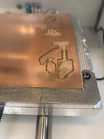
Above are the first errors I encountered so far while completing this week’s assignment. I had my trace clearance set too low within eagle and this caused the milling bit to rip up the traces. This resulted in a board that would not be able to be programmed. The other problem I encountered was the material thickness was warped and this caused the but to mill too deap into the material. This left me with a board that had lots of copper burrs that were forming many tiny shorts along the board. I tried to fix it with sandpaper and by washing it but I ended up re milling.
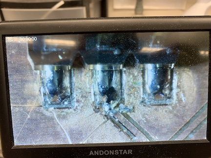
Another error I encountered regarded my soldering. I had a short that formed on the board I milled. In an attempt to fix the short I used an exacto blade to try and disconnect the possibly shorted solder from the rest of the board. In this attempt I accidentally cut off one of the traces that I needed resulting in the board being rendered useless. I afterwards milled a new board with no excess copper to remove shorts.
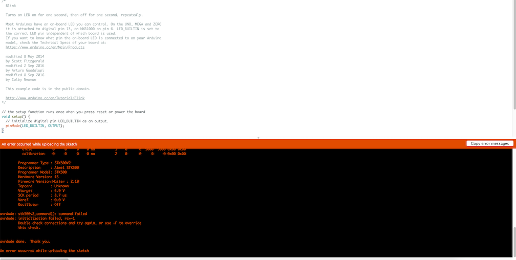
While testing my new board’s functionality I encountered yet another problem. I was not able to upload the code. I double checked that there were no bridges in my board which there weren’t and also checked that all my traces were routed correctly. I also ensured that my com port was correct and programmer information was correct and it still did not work. I am attempting to fix this error before attempting to upload final code.
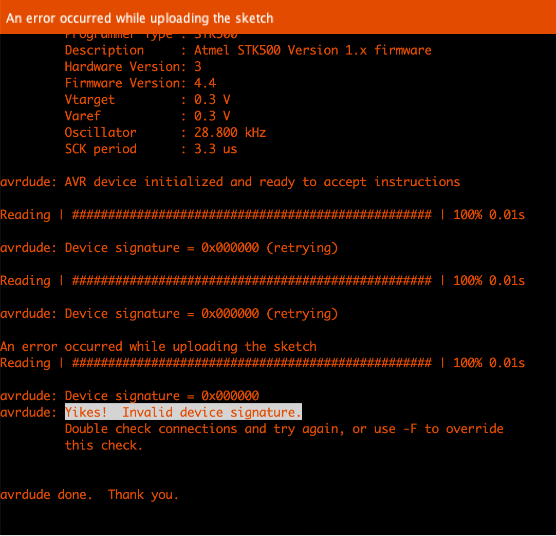
Another issue I ran into while coding my board is an error message that there is an invalid device signature. I troubleshooted this by looking towards my schematic for possible issues. I have not solved the issue but used a multimeter to test each connection ensuring there were no shorts or bridges. I also eliminated a trace that could have been causing an error.