7. Computer controlled machining
Assignment
The assignment for this week was to use our lab’s shop bot to design and mill something on the meter scale, something that was large. I want to design a step stool for this week’s assignment using pocket joints where the stool will connect. I used fusion to sketch my design and then imported it into aspire to create the tool paths
Group Work
The group work assignment for this week is to define a set of terms that pertains to our labs ShopBot as well as runa series of tests that test runout, alignment, speeds, feeds, materials, and toolpaths. I helped my group test this by creating a file that contained different geometric and non geometric figures that would display the results of these tests. Group site found here.
Design
To design what I was going to create with the shop bot for this week I began by looking through a book that described various projects as well as watching the lecture provided. I decided upon making a stepping stool. I began thinking of how I would want to assemble my step stool. At first I wanted to use dowels to connect the whole thing but later decided to use pocket joints to better support weight. I started my design in fusion by entering dimensions of how big I wanted the stool to be and parametric sizing the pocket for the joints depending on the width of the wood. I then created the plate that would be stood on by measuring the distance between the holes for the tabs and spacing them correctly. Finally I extruded the design to the width of the wood to see what the pieces would look like after being milled. I then saved the design and exported it as a .dxf which is the accepted file type for Aspire.
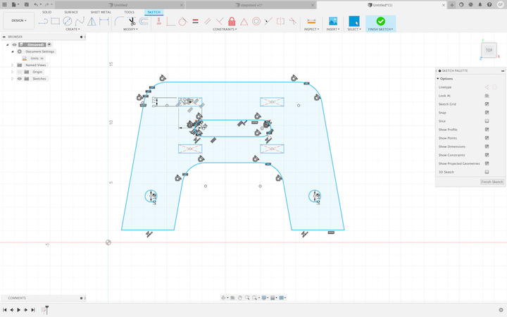
Above is the completed side piece of the stepping stool that will hold the pannel. I parametricly scaled the size of slots for the tabs depending on the width of the wood and set them apart equal distance.
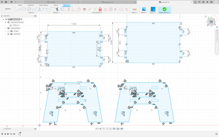
Above is an image of the completed sketch with the pannel. These are each of the parts that will be cut out and how they will look on the bed before being assembled.
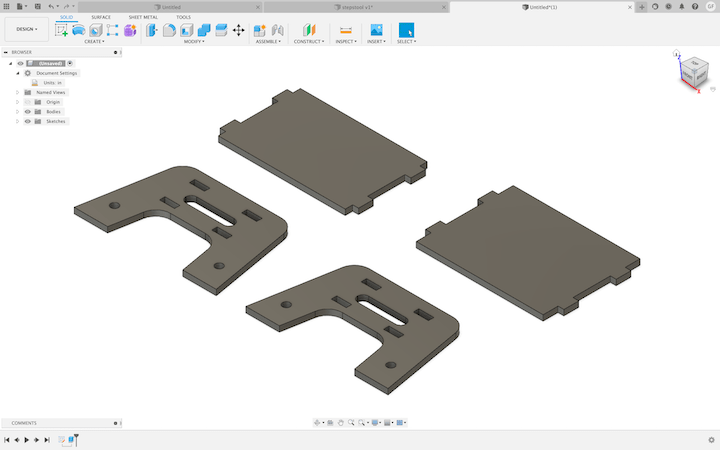
Above is each of the parts of the step stool extruded to the width of the .773 plywood I would be using to make my stool. Each of these parts fits together.
Aspire
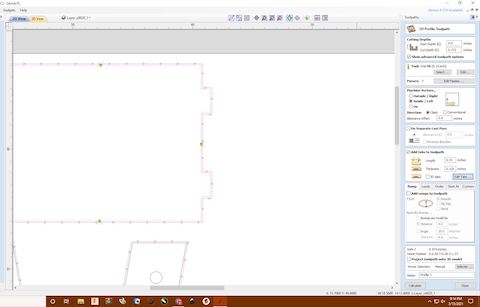
Once I had imported my file into aspire first I had to set the constraints for the machine such as wood thickness and the bed of the shop bot dimension, in my case 96x48. Then I had to move around the different parts to save material. When configuring my step stool to be cut I first had to join curves to make sure I left no open vectors in my Fusion file. Once I had this step done each of the parts were grouped together. I then added dogbones to each of the corners of the inside of the tabs as the ¼ bit I was using is unable to mill 90º interior angles. I set the dogbone size to .125 as it requires the radius of the bit I used. I then had to create the toolpaths themselves. First I selected the outside which would become the outside tool path; this is the outline of the stool. This means the bit will cut the outside line of my file to not lose size. Then a menu popped up and I selected the pocket for my toolpath type. I walked through the steps of interesting values for the tool start position and end position which was 0 and .751. I then changed the number of passes from 7 to 4 to conserve time. I then added tabs spaced around the outline to ensure the file would remain still. Finally once these steps were completed I named the toolpath and clicked calculate. This shows a render of what the machine will cut out and what remains. I repeated this process for the inside parts of each component including the pockets. I followed the same process except for instead of cutting on the outside, I picked inside so the pockets were not made too large and would not fit. I then named this towpath inside. Once calculated I could see the path for the inside rendered and combine it with the outside to see the final design rendering. I then would send this file to the shop bot to cut after individually saving each toolpath.
Dog Bones

This what my dogbone tabs look like for the pocket joints of the stool. They allow the toolbit to cut the tabs while still allowing for a tight fit between the material. I set the width of the dog bone to the radius of my bit which in this case is .125. Since the tool is a circle I have to add dogbones to inside tabs so that it can make the cut and still allow for fitment if I had no dogbones, then the bit would cut the tabs incorrectly and they would not fit.
Tabs
Pictured by the yellow “T” is each tab that will be left by the ShopBot. It auto sets the tabs to be .25 inches wide and are easily removed by a chisel. The tabs are created by the shop bot skipping over some wood that is X in width do that it remains fastened down and connected to the shop bot. I spaced them around the outside of the parts to prevent them from moving on the shop bot and messing up my stool.
Tool Paths
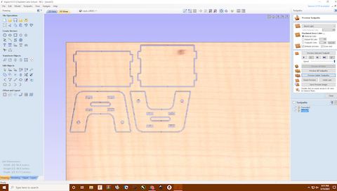
Above is the combined render of both the inside and outside toolpaths for my stool. As you can see the dogbones and tabs left behind. This is what will be produced by the shop bot and then assembled.
Shop Bot & Assembly
To begin the process of using my lab’s shop bot I first read over the Workflow. Once reading over the workflow I was ready to begin cutting out my step stool. First I put the .773 inch plywood on the bed of the Shop bot which fit perfectly. I then screwed it down along the edge to ensure no movement while cutting. I then warmed up the spindle on the shop bot by using the software. Once the spindle was warmed up I zeroed the X and Y axis about an inch away from the screw in the corner. I warm up the spindle to ensure that everything will work as intended as well as this is the process that disperses the lubricant allowing the CNC to run at full speed. I also set the “Z” value or height of the spindle to 3 inches ot start. I moved each axis by typing in the ShopBot software J(designated axis) then the number of inches I wanted it to move. I then opened my file (inside first) and ran a 2d offset to make sure it looked correct. Once I ensured it was right and had equipped my safety gear I switched to no offset, lowered the tool to 1 inch and clicked enter on the keyboard. I was then prompted to start the spindle with the button and then start the job. I watched the spindle lower and my file be cut out. Afterwards I homed the axis to the coordinates I set then repeated the process with the outside file. Once it had been cut, I moved the spindle using the “JY” command to the other end so I could chisel my step stool parts out. The bits that I used are both upcut bits as they allow for maximum material evacuation.
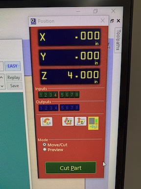
Above are the coordnites that would become the home position for the spindle of the ShopBot. It is important to document these in case of a crash where they are lost as it accounts for the screw in the corner.
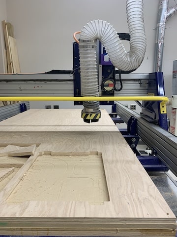
Above is a photo of me homing the spindle. I had to use the command “C2” to zero the points to where I wanted the file to start on. I did not change the position of the spindle however because it needed to remain a couple inches above the wood so I could run the offset cut test and the actual cut itself.
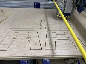
Above is the finished cut of the Stool on the ShopBot. Both the inside and outside files have been ran and the tabs are still connecting it to the plywood.
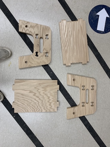
Above is the parts after I chissled them out of the rest of the plywood. I then sanded them down to remove the excess material and the spurring wood. This allowed for better fitment.
A video of the CNC running the outside file of my stepstool. It is being run creating the side pannel of the stool.
Assembly
Once removing the different pieces from the ShopBot I tested the assembly before sanding and ensuring that my tabs lined up and fit inside my pockets. This was an error I encountered on my first variation where the tabs would not fit. Once I was sure I began sanding the tabs down. I then lined them up and used a mallet to knock the tabs on one plate into the pockets. I then followed suit with the other panel. Once I had both panels in, I used the mallet to hit the other side piece into place. I then stood upon my stool in triumph of success. After I knew my stool was successful I used a low grit sandpaper to sand the rough edges and spurs down then followed it up with a smoother sandpaper. One I had everything sanded down I used a .773 inch wooden walnut download to add variation with a different color. I used a table saw to cut the dowel into small pieces for perfect fitment into the holes I made in each piece. Once everything was said and done and sanded I completed the assignment for this week.
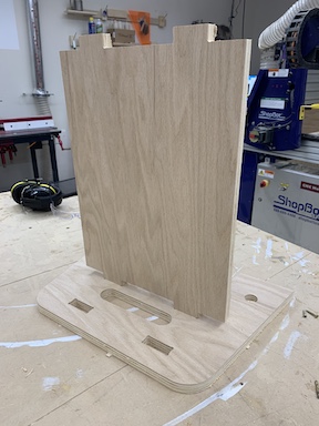
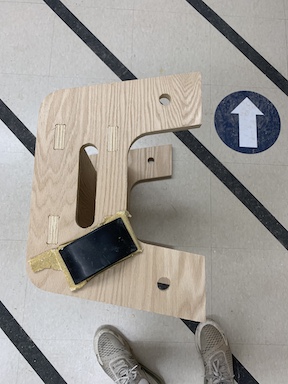
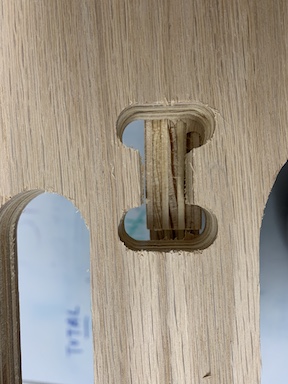
This is an image after I used a mallet to hit down the pannel into the side piece. I was glad to know that they fit properly and that the rest of the stool would as well.
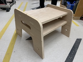
This is the completed assembled stool before sanding everything nicely. I have used the mallet to knock in each joint securly and am going to sand it down to make it look nice.
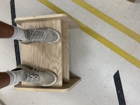
I am checking my stools stability by standing on it in this photo. It was much stronger then I expected and could easily support double my weight.
In this image I am sanding down my stool. I started by using a low grit hand sander to remove the spurrs and rough edges then I go in with a high grit power sander to make it look nice. Finally I used an ultra high grit sandpaper to make my stool very smooth.
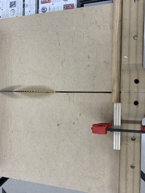
Above is me using our labs table saw to cut the .773 inch pieces of the walnut dowel. The differnce in color added a nice variation to my stool and I think it made it look much nicer. I used the block of wood on the table saw to ensure that each piece was precise.
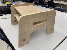
Above is the final step stool after I had finsihed sanding it down and cleaned if off using alcohol. Later on I want to apply a finish to the step stool to really make it look good.
Failures
Over the course of this week’s assignment I encountered a couple errors. When attempting to import my file into Aspire I had an error while generating the tool path where I had over 1000 open vectors. I solved this by using the close vectors tool I found which fixed this problem. I later realized my old design had structural problems and added more pocket tabs instead of using just dowels. Finally I encountered a scaling error where when I brought files into Aspire they would be larger than the ShopBot itself. I solved this by importing the files into Inkscape and then into Aspire which scaled it correctly.
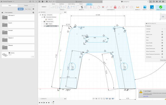
Above is the file that I improved by pocket tabs to better support the stool. I ended up re-doing the design to also allow for my clearence.
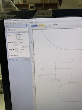
Above is another error I encountered with scaling. The problem was when I measured the dimensions of my tabs it was measuring the farthest two points, in this case across the dog bones which was inaccurate. I fixed this by removing the dogbones before dimensioning and it worked. This allowed me to accurately check the size of my tabs with different wood thicknesses in Aspire.
Above is an error I encountered on my original file. I did not account for the actual width of the wood which was .773 instead accoutered for the supposed .775 which resulted in my tabs being off by over .2 inches. I fixed this by using the scale feature in Aspire by changing the dimensions from .75 to .773 adn for my final to .751 which was the width of the wood I used on the final design.
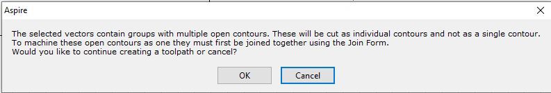
The image above shows an error I encountered very early on where I had open figures. I fixed this error by selecting each entire component and using the join vectors tool in the menu. This grouped together all of my pieces for the stool.