3. Computer controlled cutting
File Downloads
Construction kit and Vinyl Sticker
Assignment
My assignment for this week was to use computer controlled cutting and parametric design to create a laser cut construction kit as well as defining laser cutter terms with our groups. We also were assigned to create a vinyl sticker as well. Since I had become familiar with the vinyl cut process in te past I decided upon challenging myslef to create a layerd sticker. I decided to create the old American flag with 13 stars as It challenged me with lots of small components. For my parametric design I created a rocket ship construction kit as this was fascinating to me to be able to quickly adjust scaling of the kit.
While watching this week’s lecture I learned the different types of computer controlled cutting machines as well as the pros and cons of each. I also learned a little more about the laser cutters as they are the most used computer controlled cutting machine in our lab. I learned about better lab safety such as filtering out all combustion products before opening the cutter bed as well as useful techniques such as offering to avoid having a precise cut be messed up by the laser’s kerf. Below is a chart of the attributes for each cutting machine mentioned in the lecture.
The group assignment for this week was to test our laser tolerances with settings such as kerf, frequency, speed, and focus. I aided the group this week by running the tests on speed using color mapping on our lab’s 3D printer to find the optimal settings. I also defined the terms we were testing that are on our group website found here.
| Machine | Notes |
|---|---|
| Ultrasonic Cutter | Uess Ultrasonic waves to send energy to the blade of a cutter that will bluntly cut through materials. Commonly used with wood and vinyl |
| Vinyl Cutter | Common in most labs. High end models are capable of cutting 3D geometry into Vinyl for complex designs |
| Laser Cutter | Most commmon cutter, has a very wide range of functions and prices. Normally a CO2 laser that reflects off mirrors to cut wood, acrylic, and cardboard |
| Plasma Cutter | Used for cutting metal, expensive and messy process, pushes a jet of hot plasma to cut throuhg conductive metals |
| Water Cutter | Uses a supersonic jet of water and garmet to cut through almsot anything including metal and glass, very high price at 100,000 dollars on average |
| Wire Cutter | Moving of heated wires along X, Y, and Z axes to cut |
| EDM Cutter | Electrical Discharge Machining, a thing metal wire is in de-ionised water to conduct electricity using the heat to cut through metal, very expensive |
Sticker Images
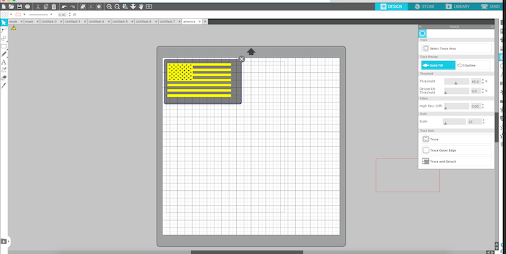
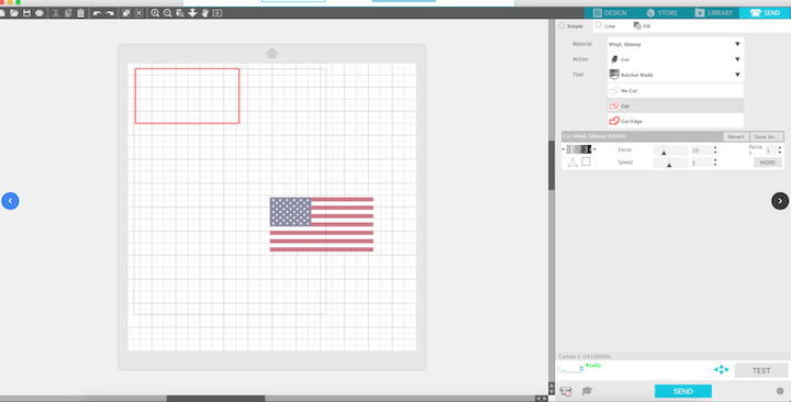
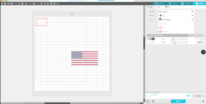
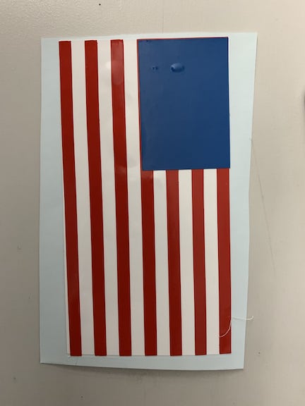
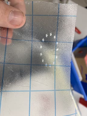
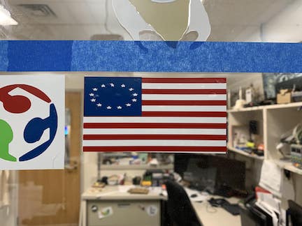
In order to begin to use the silhouette studio vinyl cutter I first had to learn about how to properly operate it and design a sticker. I used the silhouette software on the desktop which allowed me to import images that I would trace to create the layers for my sticker. I selected an american flag image and first traced the stripes. I recorded the size of the flag and created a solid rectangle as well for the red backing. This created my first two layers. I used the outline cut function and selected the entire flag for the trace. I then measured the square on the reference image that the stars would be placed on. I created a smaller rectangle that would become the blue square. Finally I imported the 13 stars. I had to evenly scale them down to fit the box. I then used the trace function to generate a trace and remove the images. Once this was completed I sent the file to our silhouette. Once the silhouette had received the file I attached different pieces of vinyl to a cut mat. I then loaded the cut mat into the machine. I double checked that the blade cut depth was deep enough to cut through the vinyl on the first attempt. I then ran the file. Once each part was complete I removed excess material and used transfer tape to layer the sticker. Once I was satisfied I placed the sticker on our fab lab window and pressed out the air bubbles.
Parametric Design and Construction Kit
For the laser cut segment of the computer controlled cutting week, our class first had to complete a group project. Our group project was to define terms such as kerf, joint clearance, and type. Also we had to figure out the optimal settings for each of these definitions on both wood and cardboard. During the group project I was responsible for defining the different types of laser cutters, documenting all the tests we did on cardboard including deciding what the optimal settings were, and using the color mapping setting of the laser cutter to aid in testing the power settings of the laser cutter. For the individual segment of the laser cutter I had to create a construction kit using parametric design. I had never even heard of parametric design before the lecture we watched so I had to first watch videos to familiarize myself with the concept. I originally began creating different shapes just messing around to see how they would fit together before deciding upon what I would make. I then used the User Parametric function on Fusion to parametrically design the tabs so they could be edited rapidly to change the way my kit fits together. I would be able to input lengths and widths for the tabs now without having to re-sketch them. After messing around I decided I would create a rocket with my construction kit with figures such as circles, rectangles, and triangles.
To complete my assignment with the laser cutter I first created a file in fusion before operating the cutter. I used fusion 360 to create a circular piece, some rectangles, and triangles. I used parametric design to create the slot taps in case of material thickness changes. I then assembled my file in fusion to ensure it fit like I expected. I then exported my file as a .DXF to the printer. Once the file was on the cutter I read over a workflow. I then put the cardboard on the laser cutter and began the setup. I first had to make sure the laser was focused by using the auto focus feature. I changed the setting so it would be optimized for cardboard and then ran the file. I ran the file twice to ensure that it would be fully cut out. Once it was all cut out I assembled it to complete my assignment.
Parametric Laser cut kit
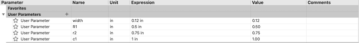
Above are the user parameters I used to allow me to adjust the tab sizes quickly for my construction kit. As you can see in the photo I have parameters set for each of the different tabs as they indent different lengths in each shape. I also have set parameters regarding the tabs width so that they can be adjusted for any sort of different material. At the moment they are sized for 1/8th inch cardboard.
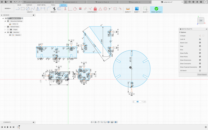 Above are the sketches of figures that I will be using to create my rocketship construction kit. I will use the rectangles and circles to create the cylindrical body of the rocket and the triangles for the fins and nose cone of the rocket. Although I have parameters, Fusion automatically used the constraint feature to make sure all my sketch geometry still was aligned and I additionally used the constraints to line up the tabs to be evenly spaced apart. This sketch will be exported as a DXF to be cut on our labs laser cutter and will be assembled.
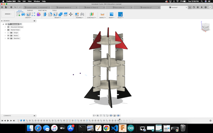 Above is what the kit looks like all assembled in fusion. This shows the joints connecting the circular and rectangular pieces to form the body as well as the triangles forming the nose and fins of the rocket. I also added a nice color to the rocket by the appearance function within fusion. When I cut this design out of cardboard it should line up exactly as it is in fusion.
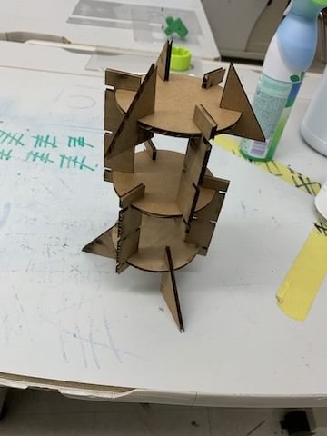
This photo above is the final working assembly of my rocket. This is the design where I got all of my joints to connect properly and allow for the assembly. As you can see in this photo the rocket is free standing and looks almost exactly similar to the rendered design in fusion 360.
Video of Assembly
Failures
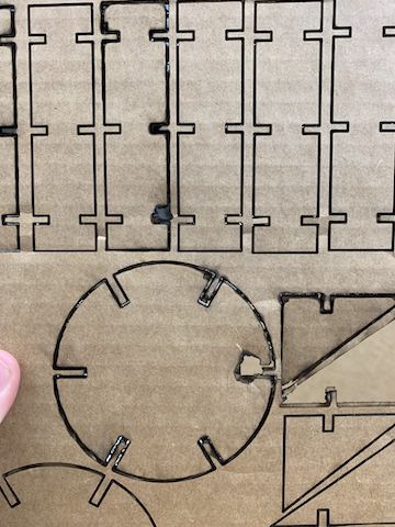
The first image above shows the problem where I was attempting to cut components for my construction kit while the laser itself was out of focus. The laser itself was not focused enough to cut through which caused me to have to run the job over and over again. As I had to run the job multiple times this caused the embers within the cardboard to ignite and cause a fire which I had to extinguish. This ruined the component causing me to have to restart I fixed this by using the auto focus on the laser which allowed for the cut to be precisely cut it the first time
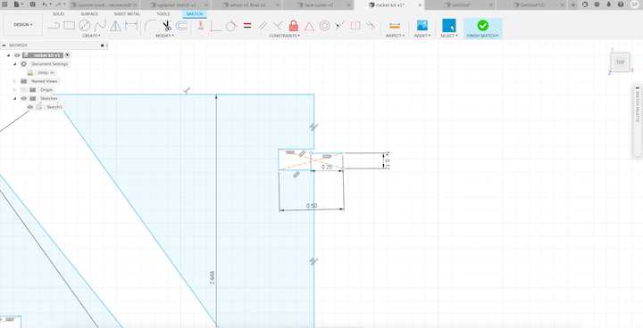
Above is a video of my failed joints. I had created a rectangle and trimmed it so everytime I tried to edit the parameter it would only change the geometry of the tab instead of actually chnaging the width of the tab. This video shows the resulting failed assembly. Also seen in the picture above you can see in my Fusion sketch how the parameters dont line up with the tabs and they were in fact just changing the geometry.
Conclusion
Concluding this week’s assignment I learned alot about what optimizes the settings for the laser cutter and the correct settings to cut cleanly.To design in my file for the construction kit I used parametric design which means I could alter my joint sizes. I had never used this before and it saved me a great deal of time as I messed up my thickness 2 different times. On our vinyl cutters I had used them before but never gone in depth. During this week the construction of a layered sticker gave me perspective on the steps to layer it correctly. I also had to scale different parts to ensure it looked correctly so I was able to weave out excess material. This changed my mind and instead of weaving 50 stars I selected the 13 star pattern.