11. Output devices
This week I worked output devices and try to think about how to connect with my final project.
In the end, I may use the joystick to control the motor, and at the same time, use the switch to control the extended functions on the ROV underwater robot. I learned that the process of controlling the motor with a single chip and corresponding electronic components is relatively complicated, so I will first try to use some simple components to learn output devices to understand the working principle of PWM. First I will try to learn to make Hello.RGB.
Hello.RGB

Next, I will redesign my own Hello.RGB based on the existing data.
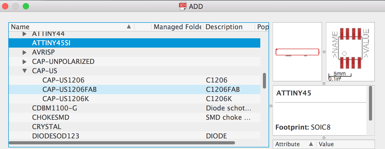
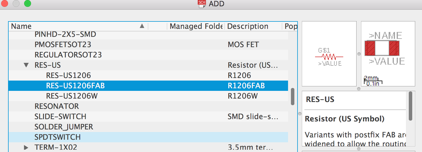
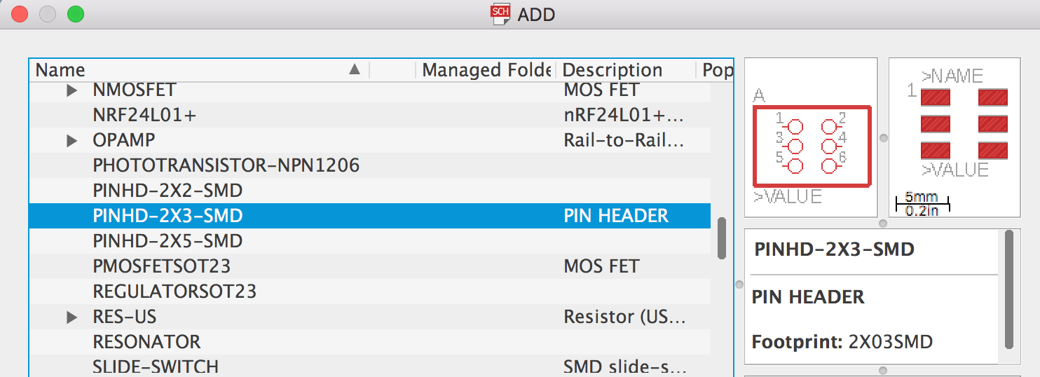
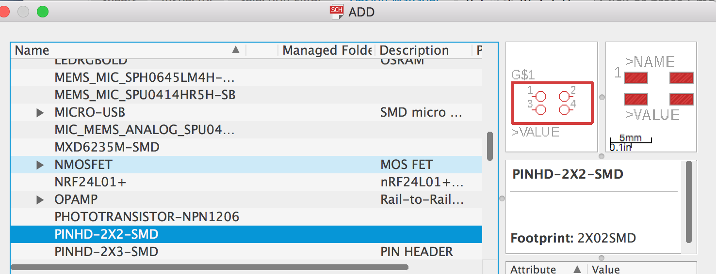
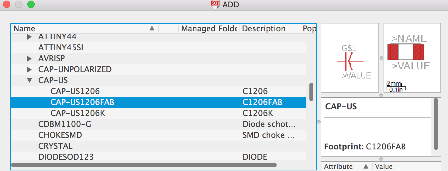
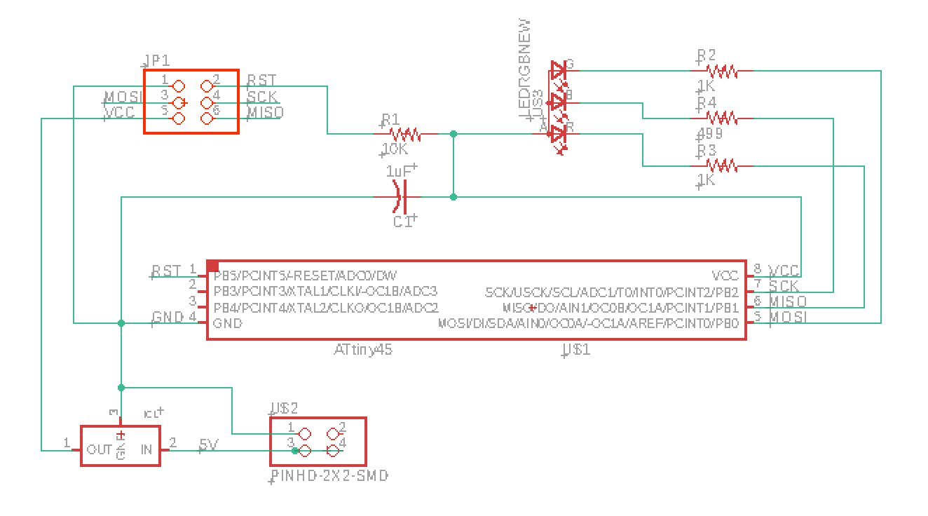
First, I will design the schematic through the Eagel software.
ATTiny45
RES *4
PINHD-2*3
PINHD-2*2
Capacitor
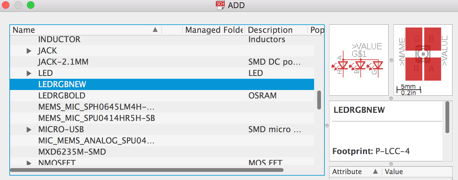
LED-RGB
Regulator
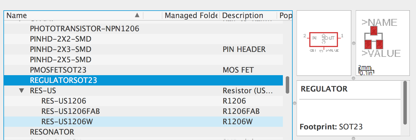


Here I chose the wrong component FET
LM3480IM3X-5.0 SOT-23 100mA 5V should be the right one. Their appearance is too similar between Field effect transistor/transistor/ three-terminal regulator.
ATTiny45-SSU
Capacitor- 1uF
RES1-10k
RES2-1k
RES3-1k
RES4-499
LED RGB
5V Regulator
PINHD-2X3-SMD
PINHD-2X2-SMD


Useful links
Code Example
int led1 = 1; int brightenss = 0; int fadeAmount = 5; int led2 = 2; int led3 = 0;
void setup() { pinMode(led1, OUTPUT); pinMode(led2, OUTPUT); pinMode(led3, OUTPUT); }
void loop() { anglogWrite(led1, brighness); anglogWrite(led2, brighness); anglogWrite(led3, brighness);
brightness = brightness + fadeAmount;
if (brightness == 0 || brightness == 255)
delay(30);