6. Electronics design
This we had learned the “Electronics Design” course. After “Electronics Production”, I’ve learned more about Electronics this week. Actually, this part is what I most want to promote myself. And lots of before students assignments help me much.
Assignment
Group project: + use the test equipment in your lab to observe the operation of a microcontroller circuit board
Individual project: + redraw an echo hello-world board, + add (at least) a button and LED (with current-limiting resistor) + check the design rules, make it, and test it + extra credit: simulate its operation
Echo Hello-World Board
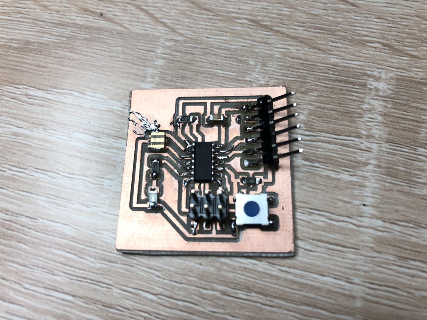
Through the sample of the Echo hello-world board then change the original “Electronics Design” and add (at least) a button and LED (with current-limiting resistor). The sample circuit looks like the below image.
I planed to use Autodesk software EAGLE to redesign the new circuit board. At first, I installed the EAGLE and create a new project “Electronics Design”.
What I found this tutorial
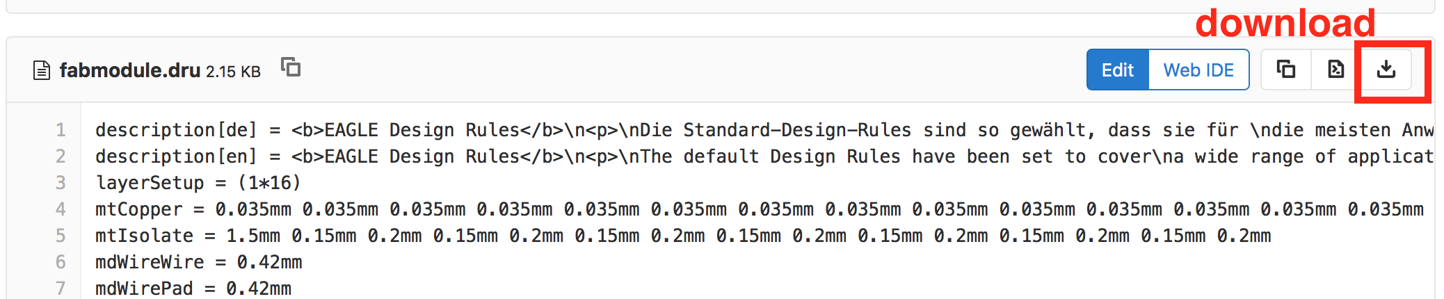
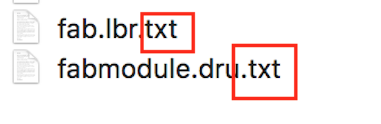
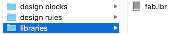
I use Mac for working. Maybe the files you download are named “fabmodule.dru.txt” and “fab.lbr.txt”. Just delete the “.txt”. Next, find the right folder where the above two files should be.
Username > document > EAGEL > design rules

Username > document > EAGEL > libraries
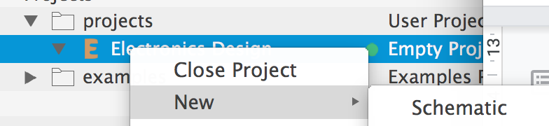
Then, we need to install the fab library in the EAGLE. Under my new project “Electronics Design” create a new schematic.
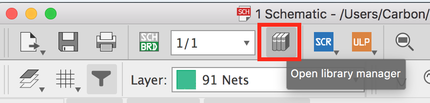
Open at the top line icon is the library manager.
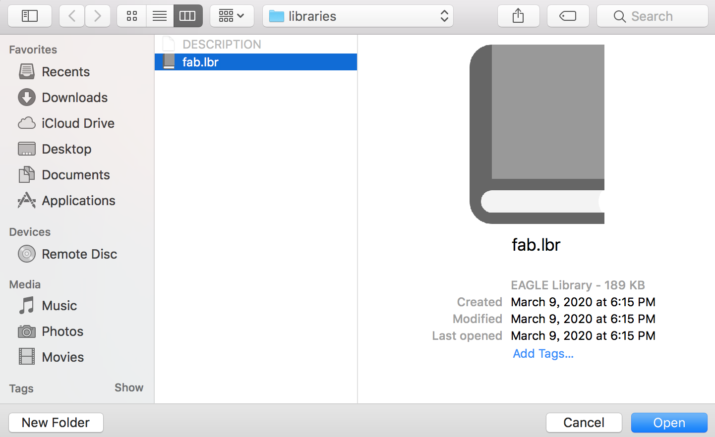
In this dialog under the tap of “In Use” through “Browse” find the “fab.lbr” that we download before and open it.
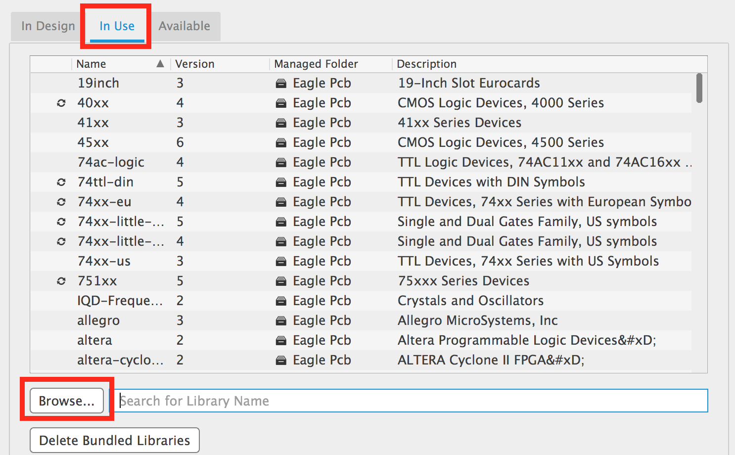
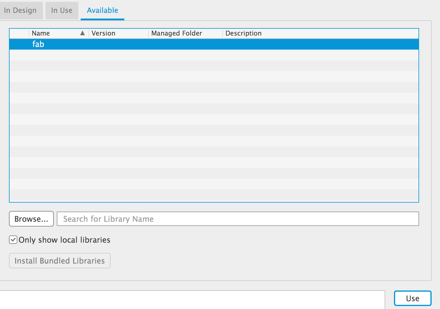
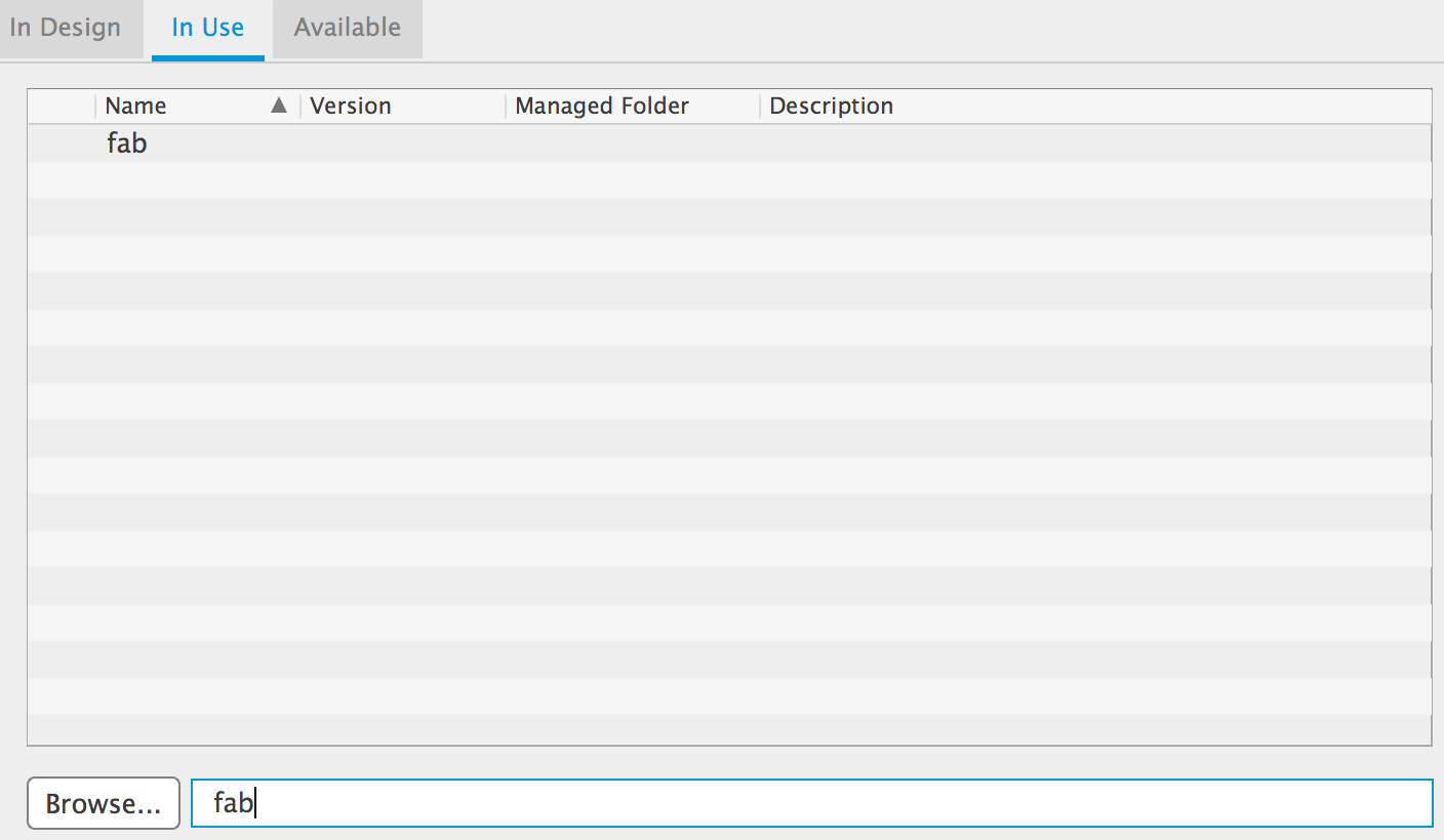
Make sure that the fab.lbr is in the “In Use”. If not you can find it in the tap of “Available”
Then choose the “Use” button and let “fab.lbr” occurs in the tap of “In Use”.
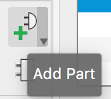
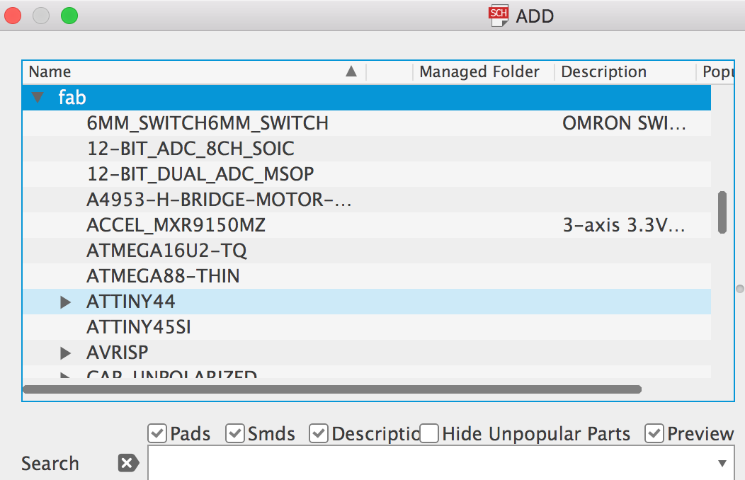
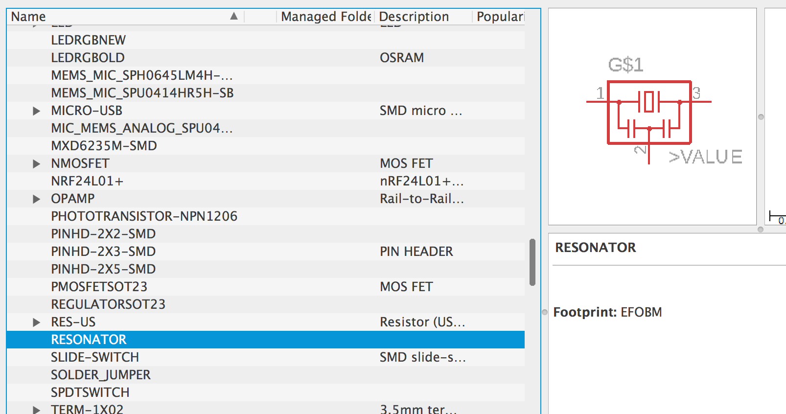
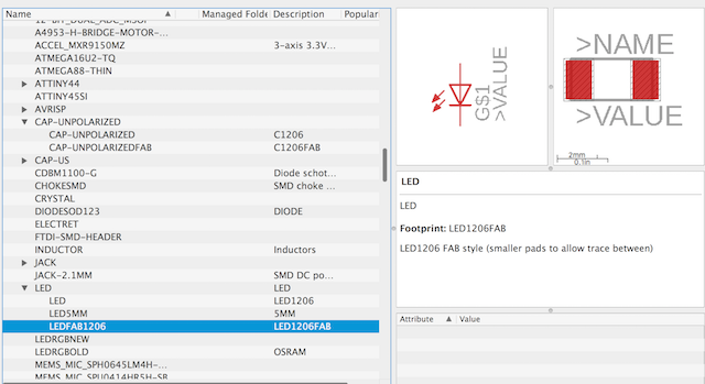
Next, we can start our design and add the Fab electronics components from the Add Part Icon.
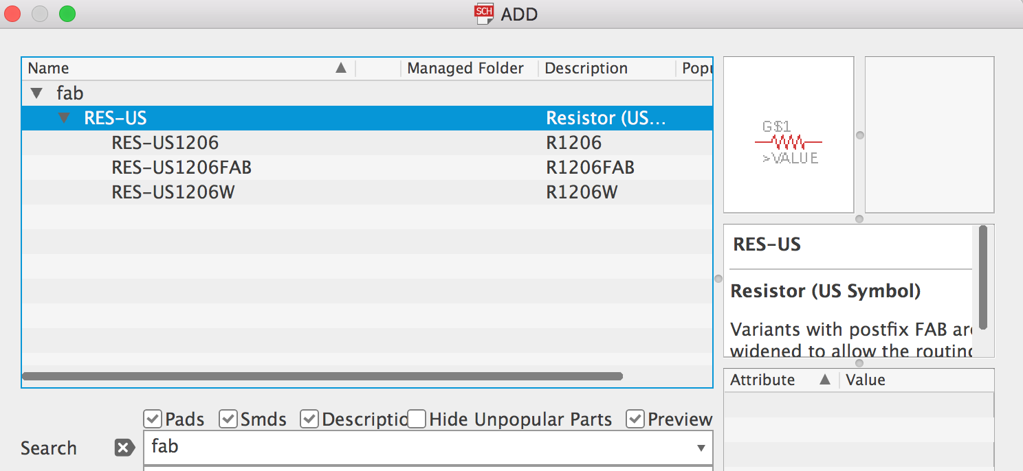
Here is a small issue I met is do not search the name “fab” directly. Because I only find three RES in the library. I don’t the problem why happen that but just find “find” through roller mouse.
Components
After we finished adding the fab.lbr we could start electronics design literally. We should know all of the components that we need.
Here is the original “Echo hello-world board” list and one more button and LED.
+ ATtiny44 microcontroller x 1
+ Crystal 20MHz x 1
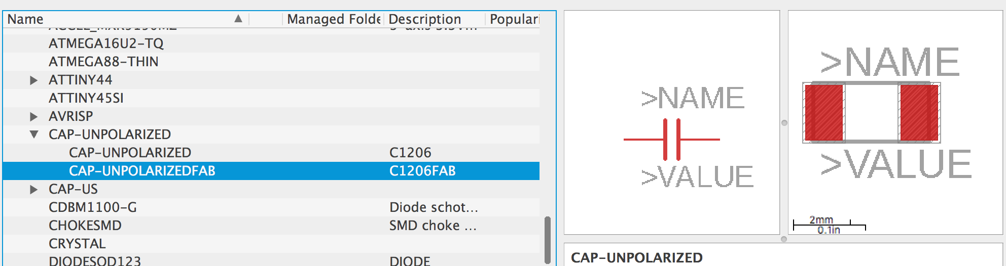
+ Capacitor 1 uF x 1
+ Resistor 499 Ohm x 2
+ Resistor 10K Ohm x 1
+ LED x 1
+ SMD Buttons x 1
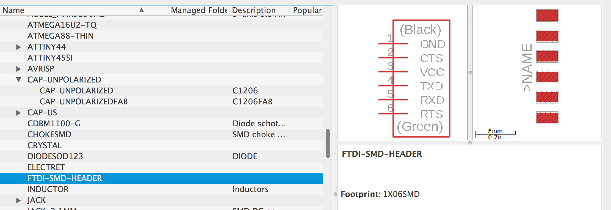
+ 6 pin FTDI x 1
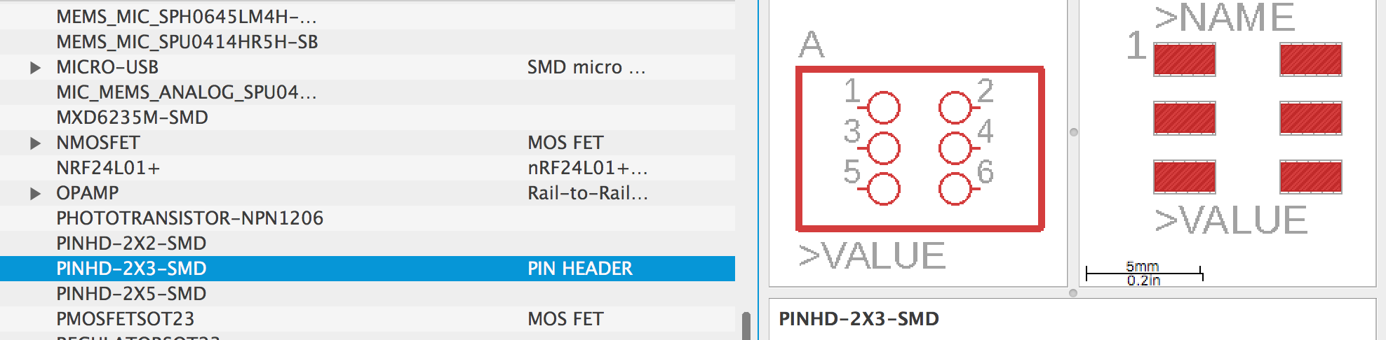
+ 6 pin header x 1
Add all of the parts one by one.
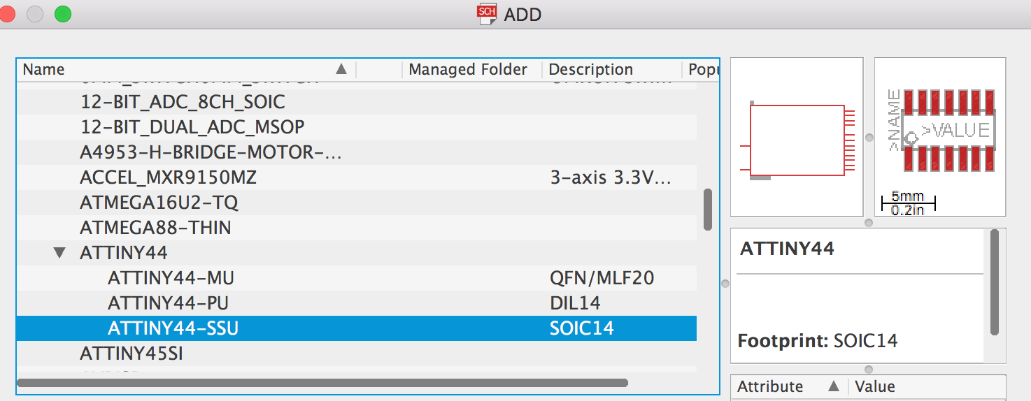
ATtiny44 microcontroller (SSU)
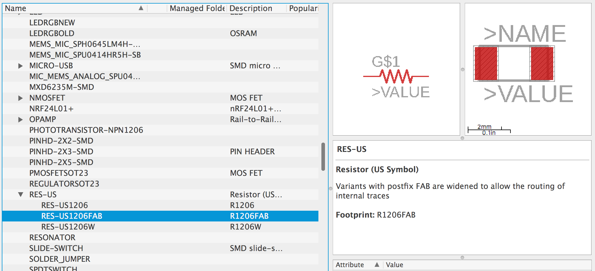
Resistor(FAB)
Crystal 20MHz
Capacitor(FAB)
6 pin FTDI
6 pin header
LED(FAB)
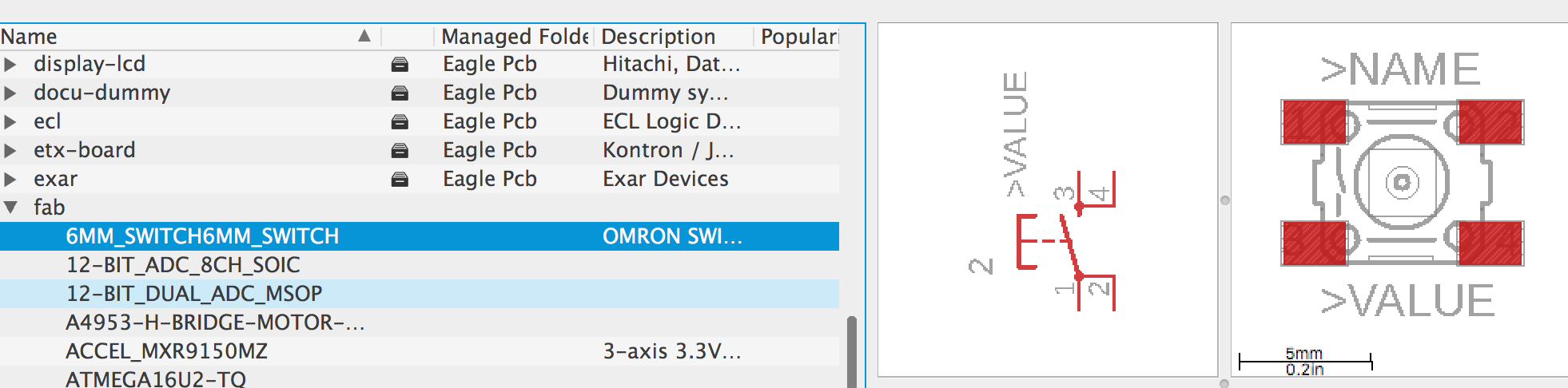
Button
Schematic
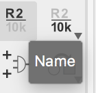
Now I’ve added all of the components. Then I need to change their names and wire them.
We can use this command “Net” to connect every pin among components.
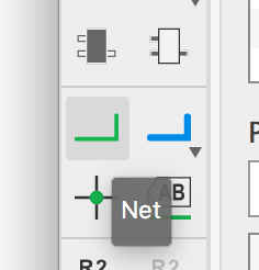
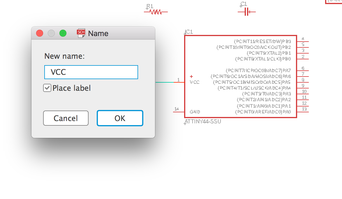
But as you see there are many componets on the screen. For clearly to observe it. I used another way to connect different pin. Firstly make a new wire connect the pin and then name the wire what you want to connect. For example, there are many pins need to attach to VCC(+5V). So I just need to name all the related wires to “VCC”.
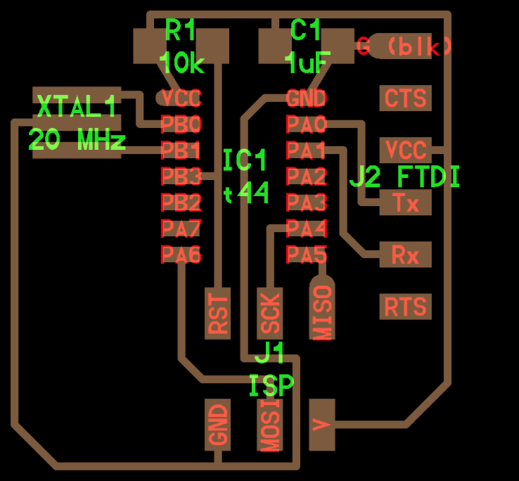
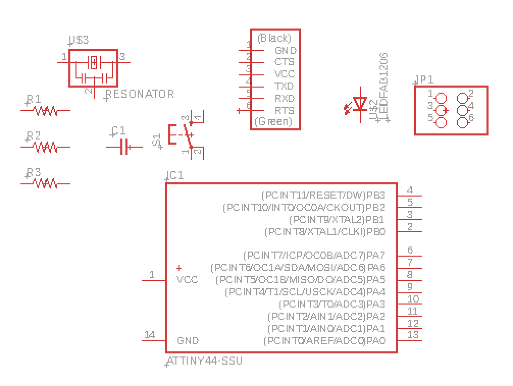
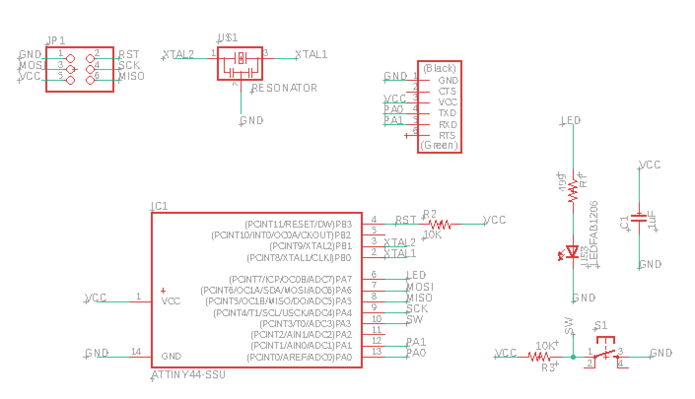
At last, I finished my board of the schematic image.
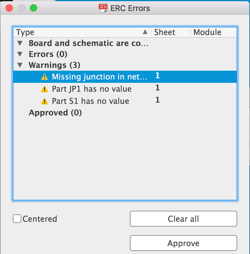
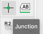
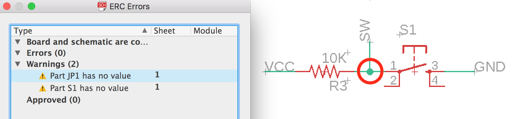
When I finished the schematic file, I checked the ERC Errors. Here found one error is “Missing junction in net connection”. Then I used the “Junction” command to joint these wires.
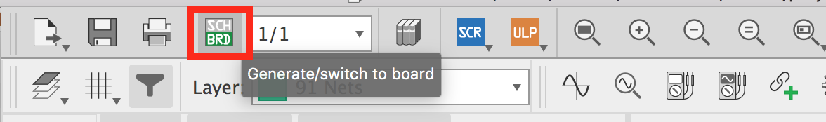
Next is to generate the schematic to board.
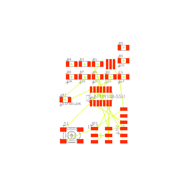
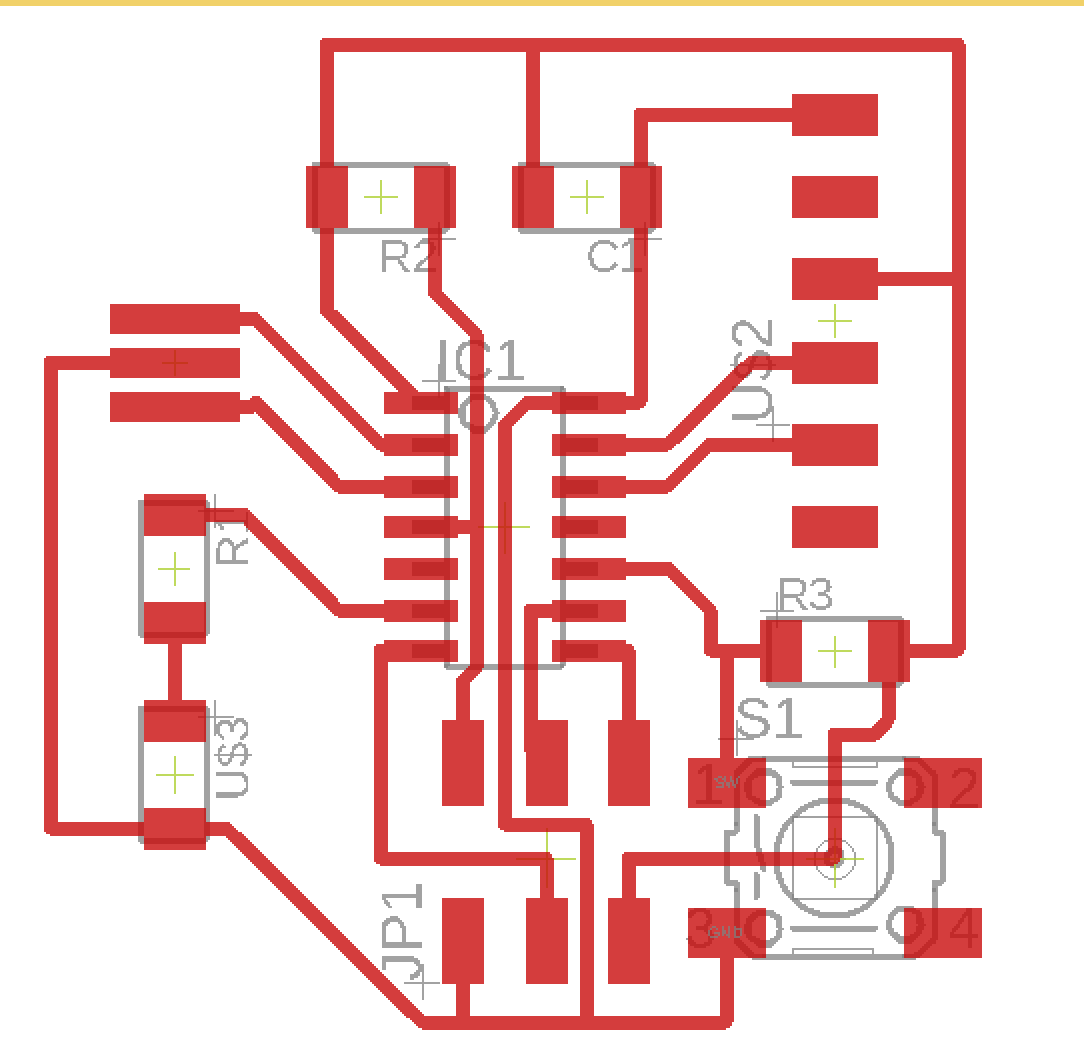
You will find what is full of mass wires. So I need to replace every part and let all the wire could be seen clearly. In the below image I added some more resistors we may use them as jumpers later. If not we could remove extra ones.
And use the command “Route Airwrie” to make the specific wire.
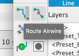
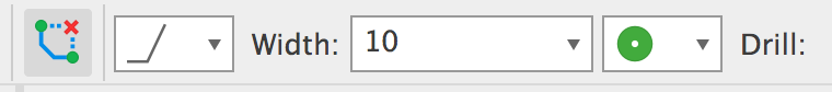
Here could change the parameter about the Route Airwrie, like the shape and width.
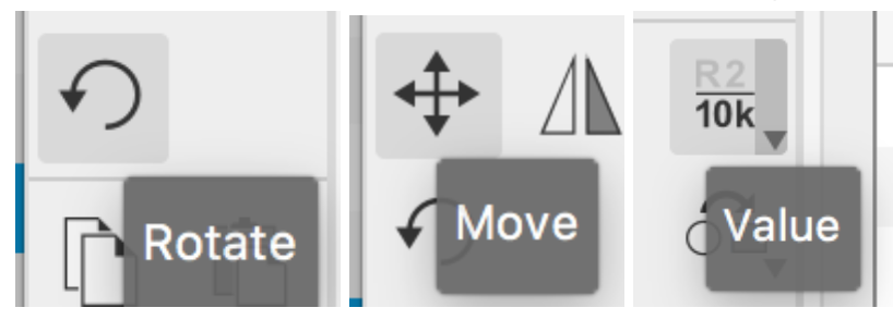
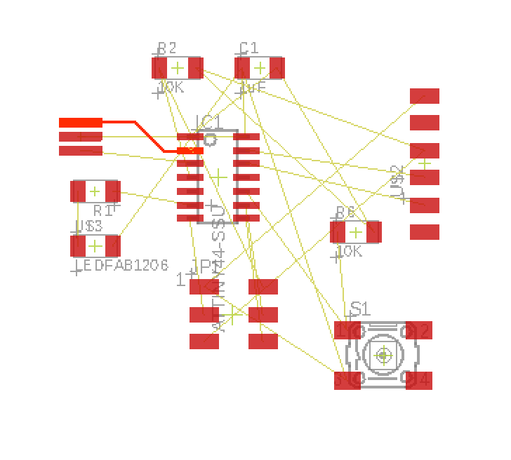
This part is really important that it depends on how reasonable that you placed every componets. I used the “Move” and “Rotate” command during this part. Because this time we make one side PCB board. So all of the wires couldn’t make the crossing. If we could avoid that we may use a resistor as a jumper to solve the problem.
Finally, I made it. It takes me a few hours.
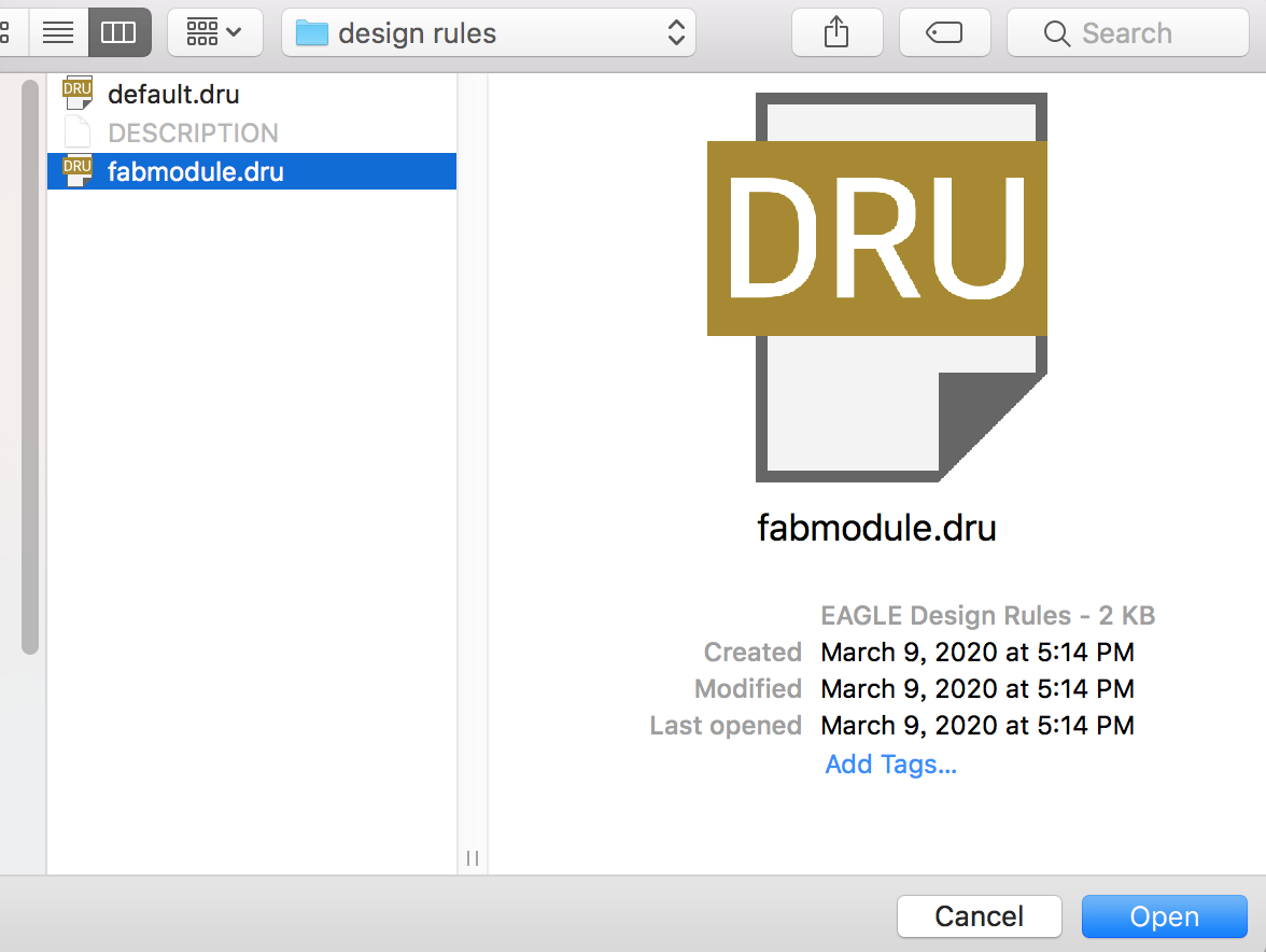
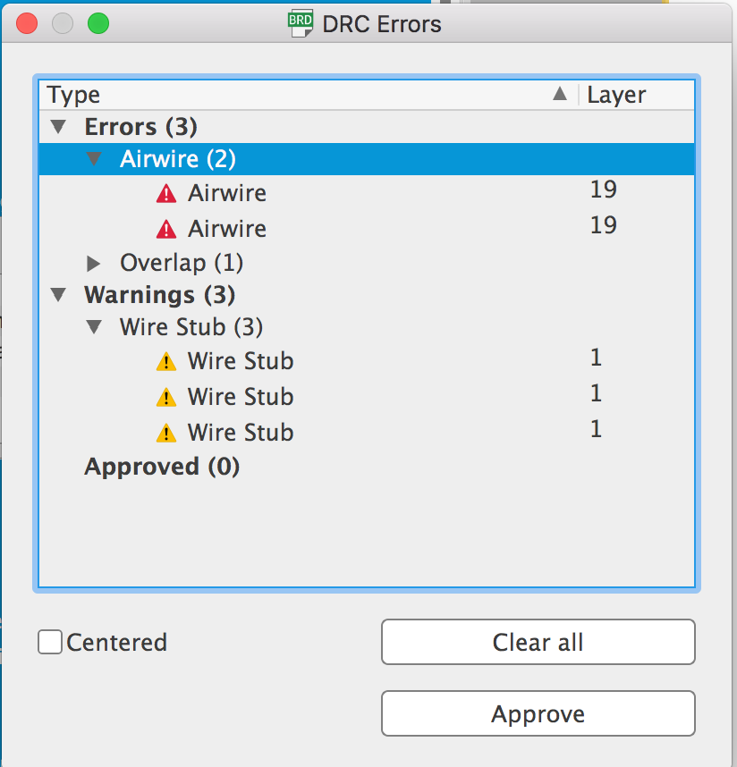
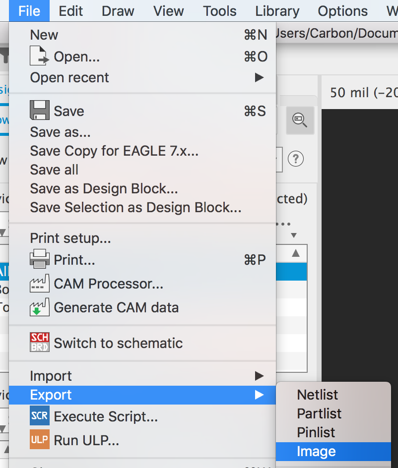
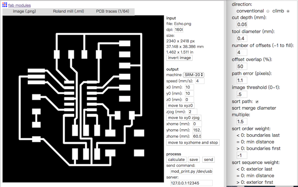
Using the fab module rules to check if there are errors.

Load the file that I downloaded before.

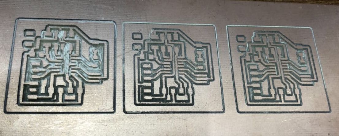
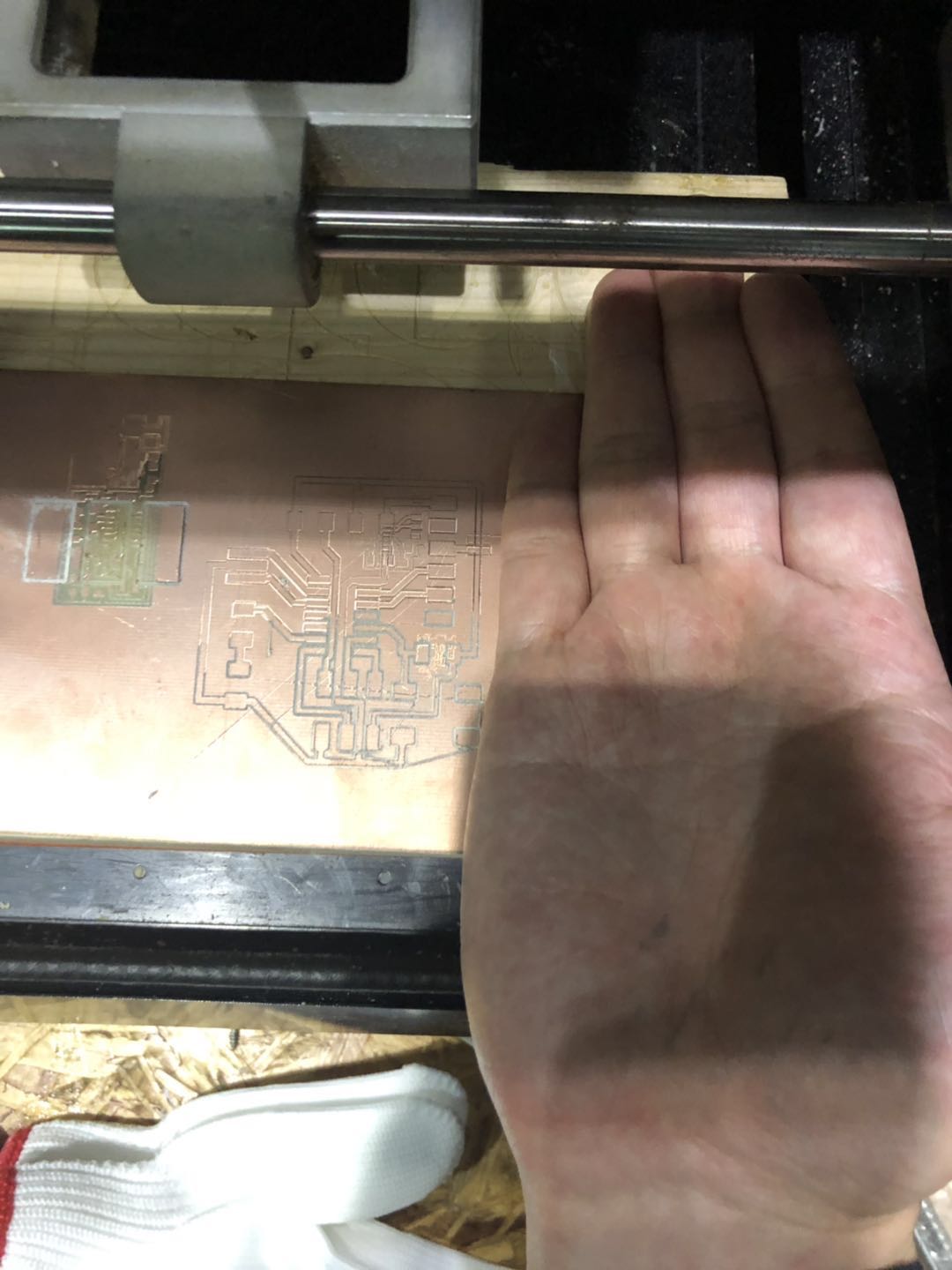
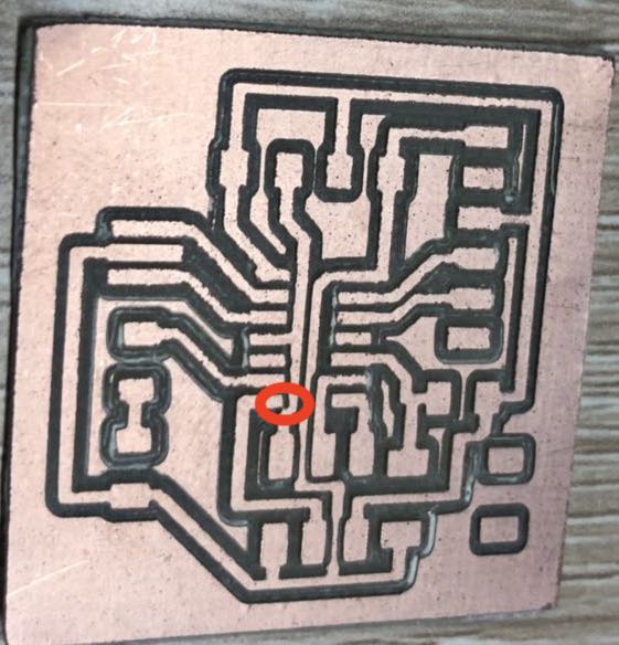
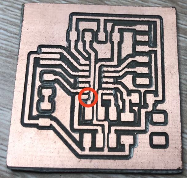
Traces & Outline
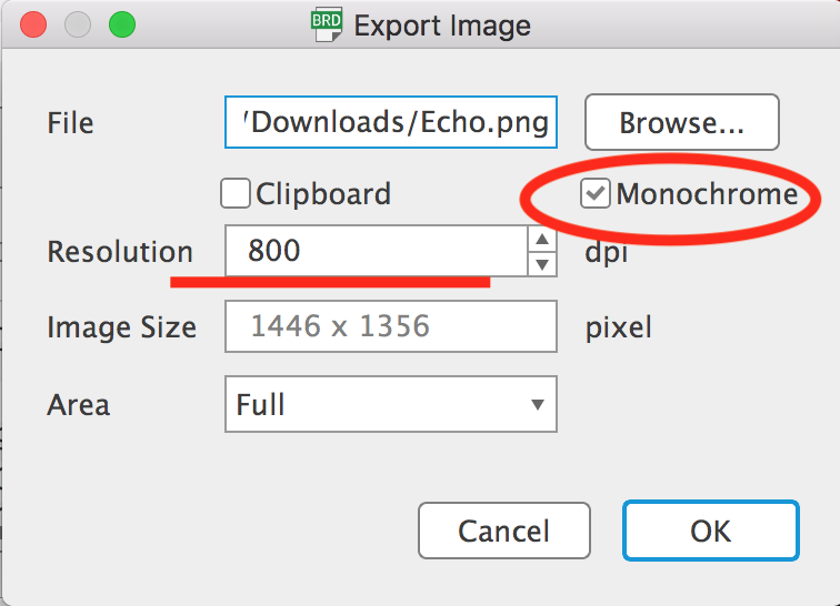
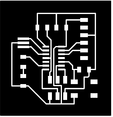

PCB