5.3D Scanning and Printing
This is the 5th week of the Fabacademy course that we are going to work on 3D design.
Assignments
The group assignment is testing the design rules for your 3D printer. The individual assignment: A: Design and 3D print an object. B: Using 3D scan an object and optionally print it.
3D Pringting
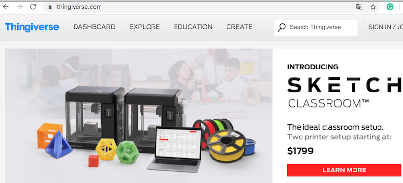
Firstly I explored many modules on the Internet from this website Thingiverse. This is a very useful website where you can find a lot of 2D or 3D modules and could also inspire ourselves and reduce the development time with the open-source documents.
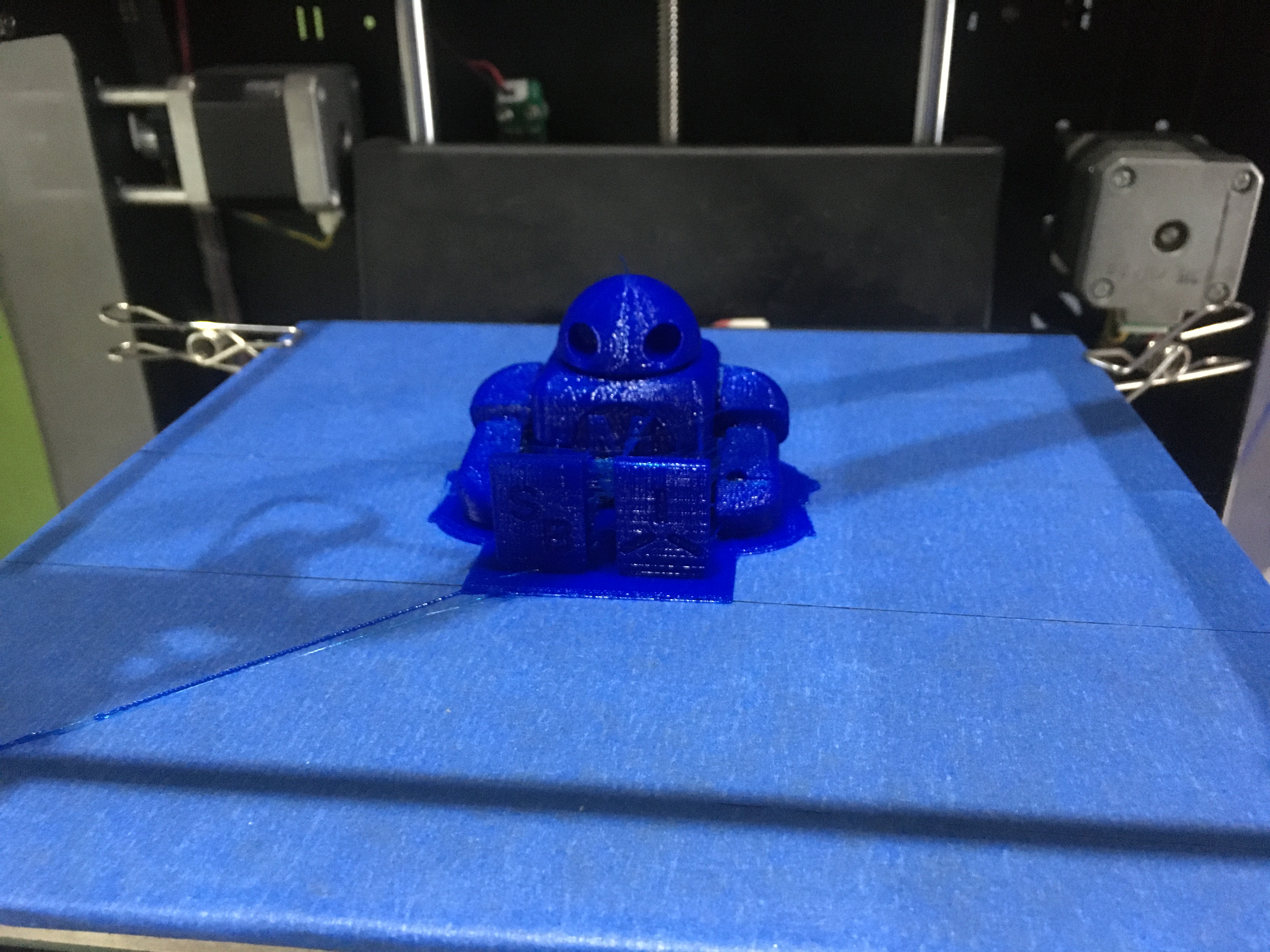
Now let’s going to make a real product through Thingiverse. Like what I found is a Maker Faire robot then download the file
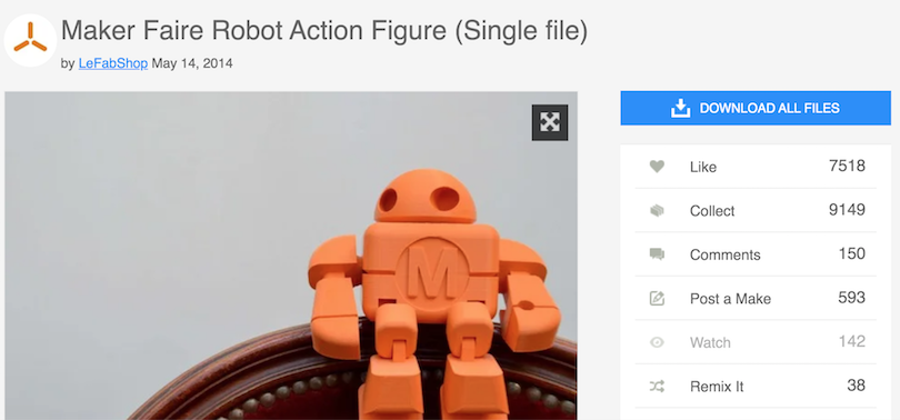
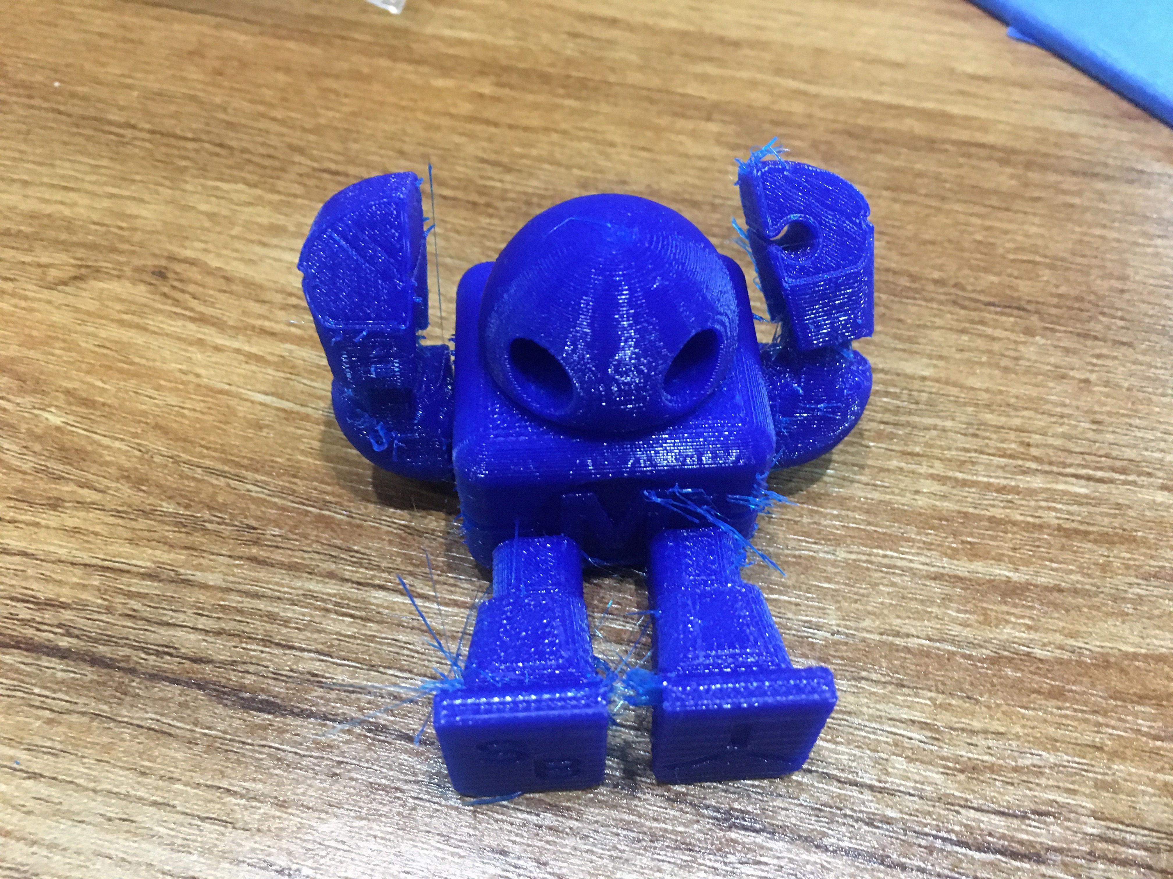
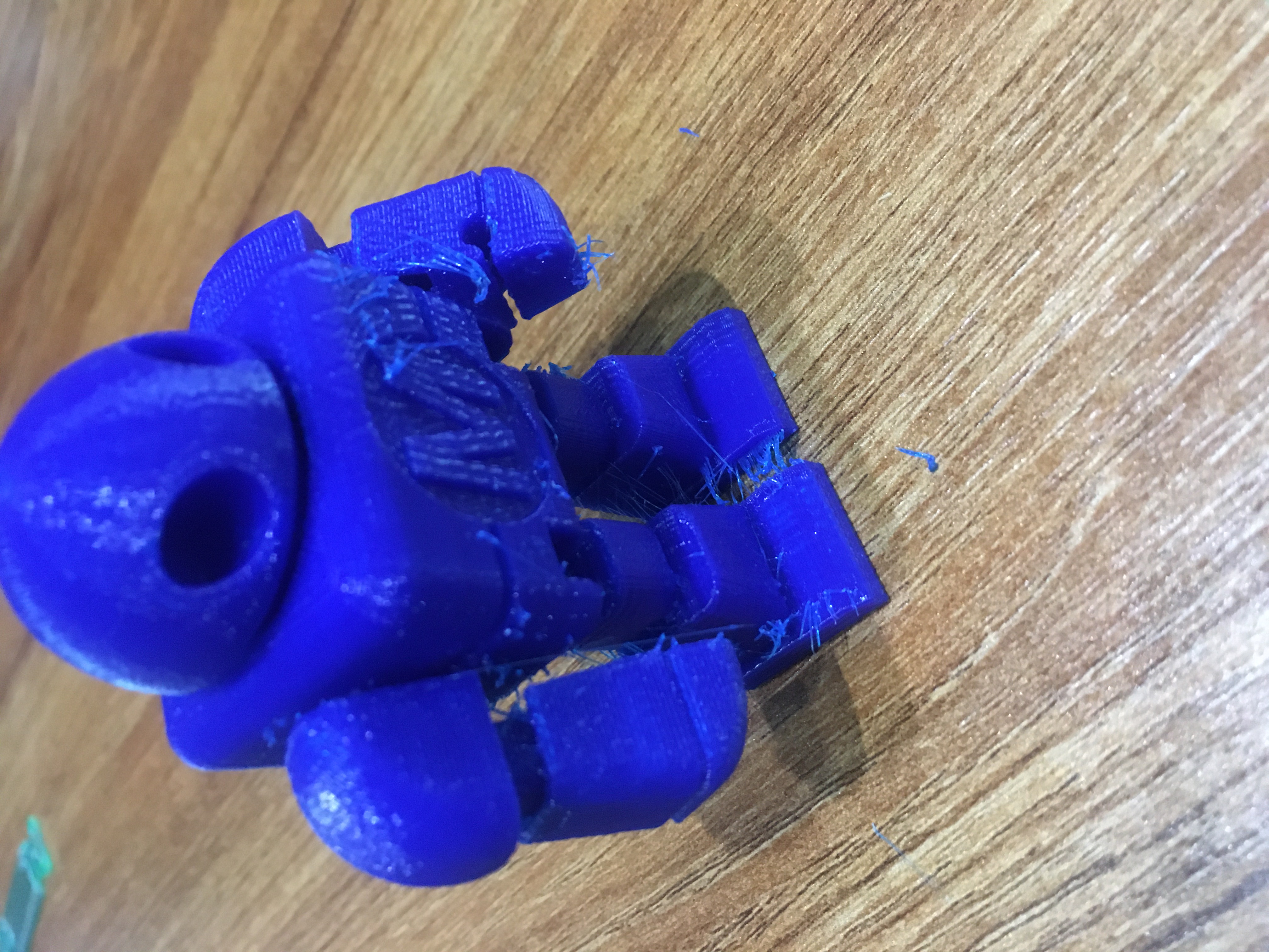
You will found that this file is interesting the robot is created by one part but after printed you will see it’s arms and legs could move a little. This point is useful for my further projects thoughts.
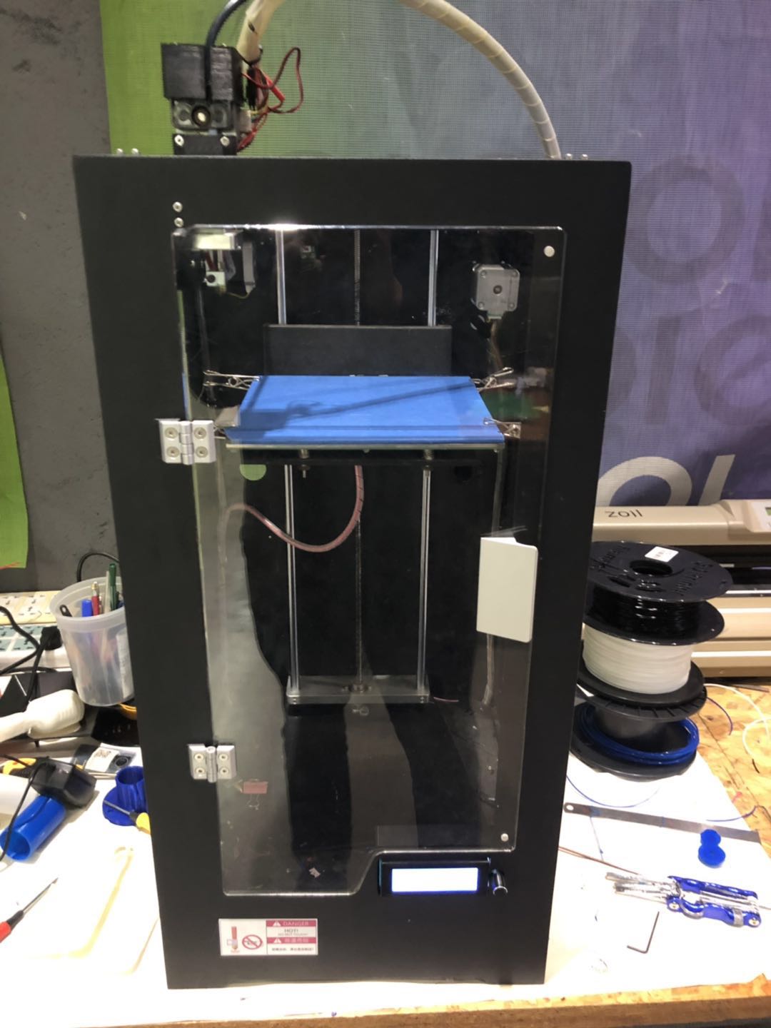
First of all I what I used is a Chinese version 3D printer. It is a FAM type 3D printer that can process PLA, ABS or some silica gel material.
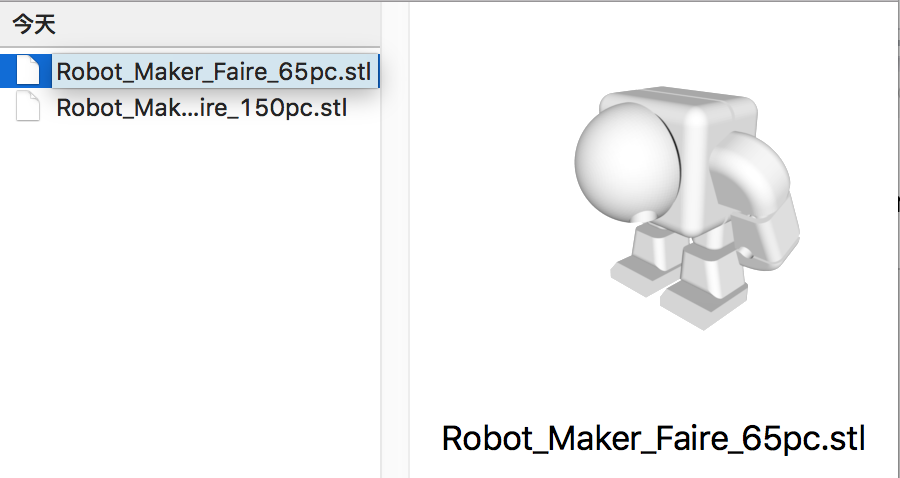
Next, we found an STL file through the software “Cura” to process it.
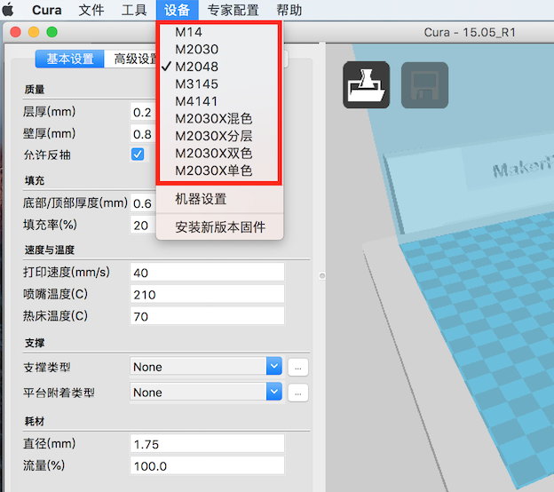
Choose the certain 3D printer equipment that we use.
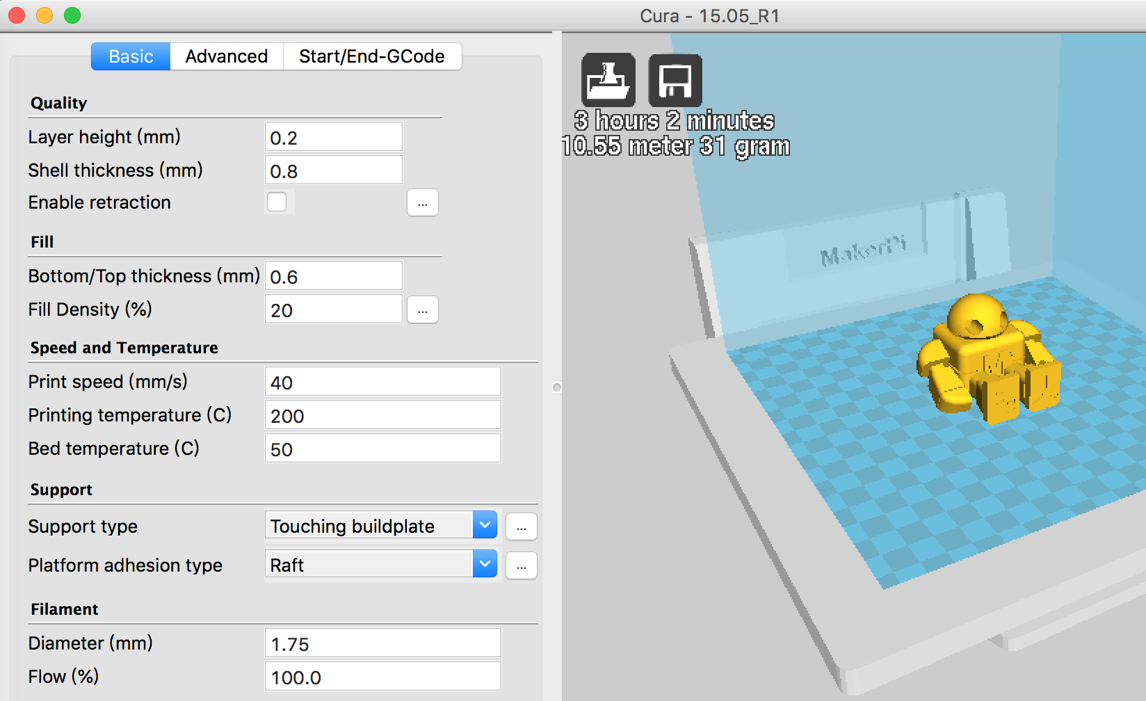
Load the STL file and set the parameter like below. Include the quality, fill, speed, temperature, support, filament.
I choose PLA as the material so I need to set the filament 1.75mm diameter. And the temperature is also important as 180-210℃. If you want to use ABS the temperature should be around 230℃.
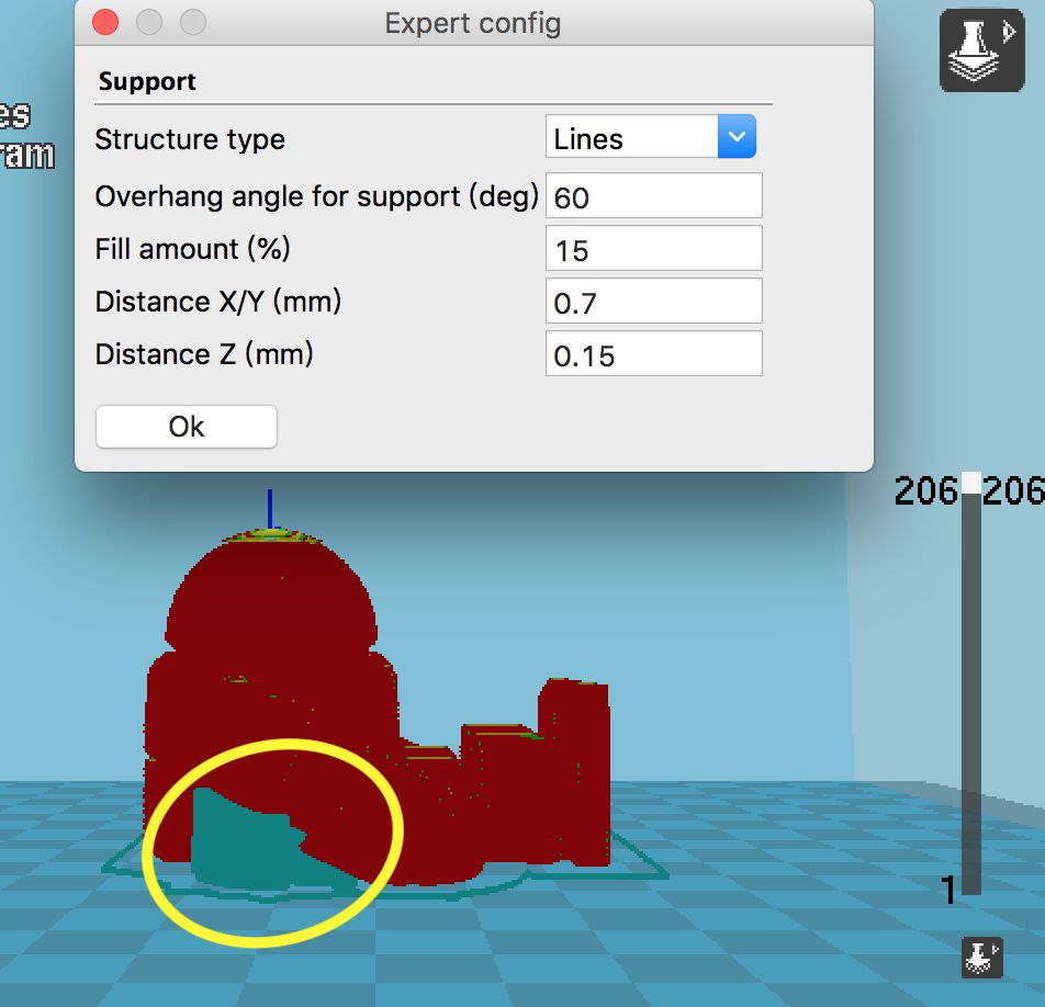
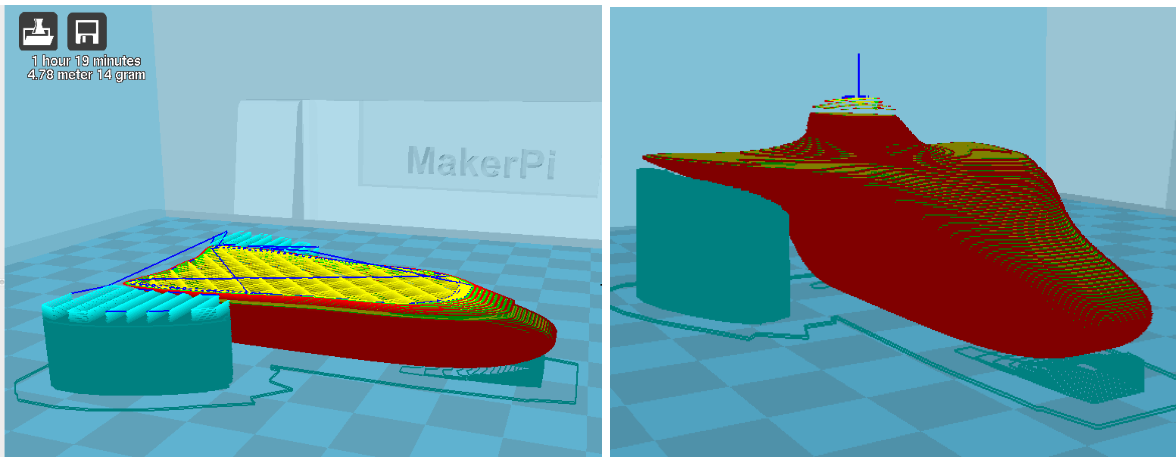
Another point is the support. Like what I showed below in the yellow circle area. The green part is the support for the robot arms. And we could change the detail in the dialog.
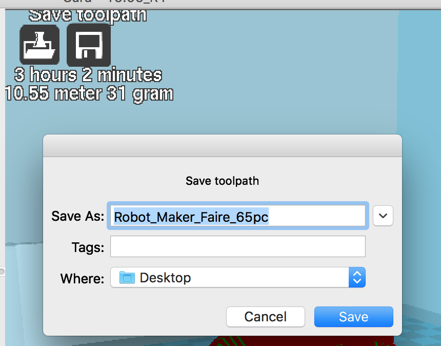
At last, save the g-code file then keep it in an SD card and plug it into a 3D printer.
Then through the 3D printer operating panel choose the file that you want to create.
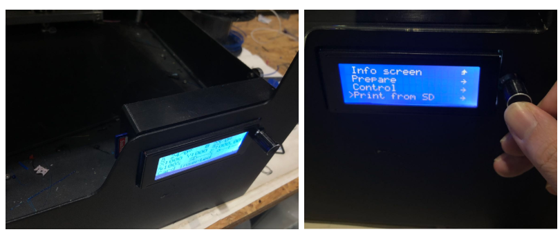
Next is to wait 3 hours for the printing.
Printing Video
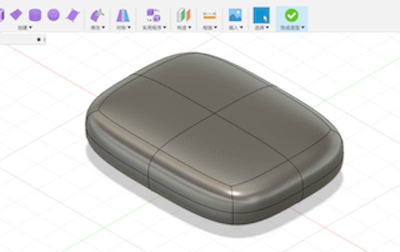
Design and Print my original ROV project
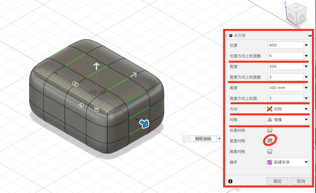
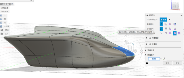
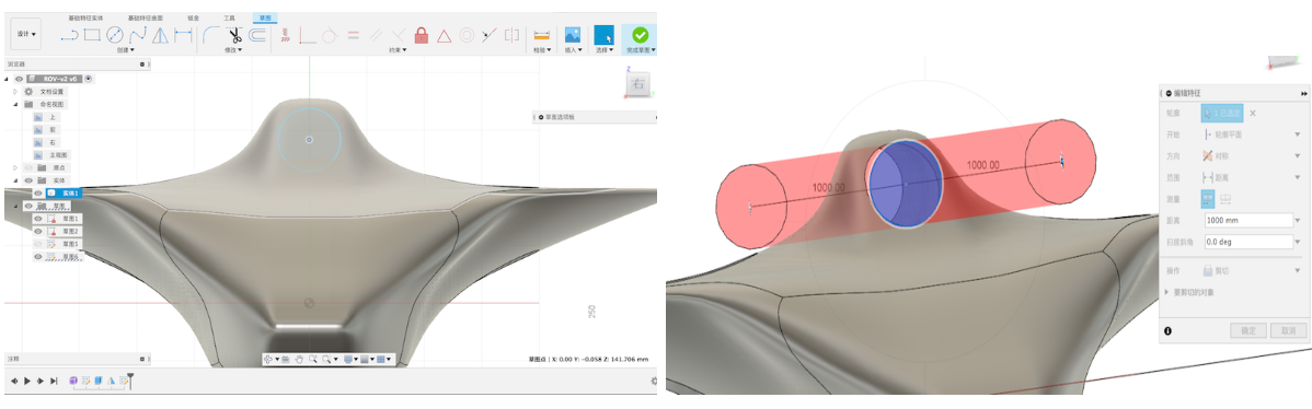
Using the command “Create Form” to make a box and setting the creatin diameter.
The important parameters are width faces/height faces/symmetry(mirror)/width symmetry.
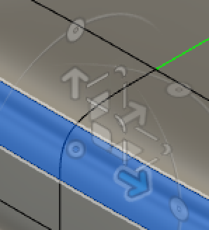
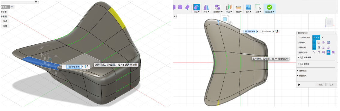
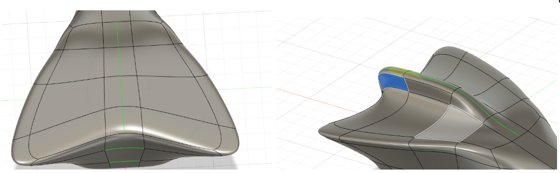
Under the “Modify” there is a command “Edit Form”. Through this tool to change the form shape which parts you choose.
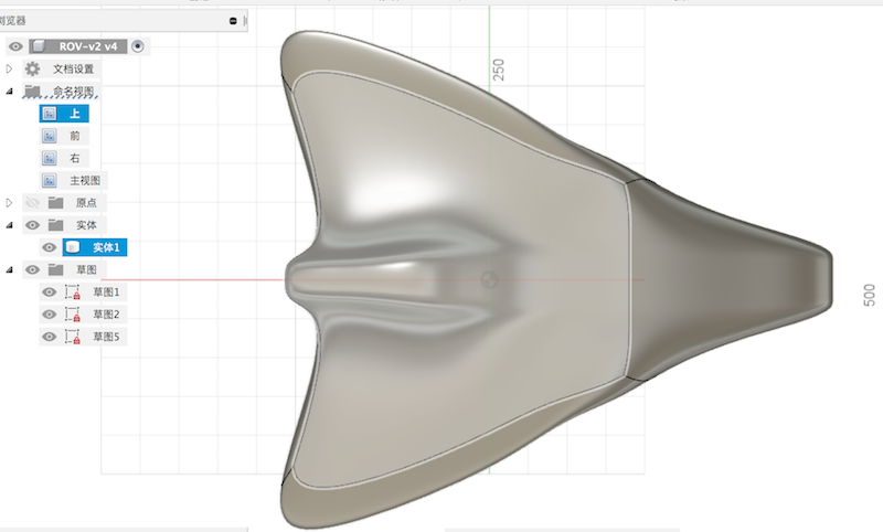
Next step I’m going to make 3 holes for this ROV’s motors.
Create a new sketch for a circle whose diameter is 100mm.
Extrude the circle at 300mm.
Using the mirror command the create the same object to the center.
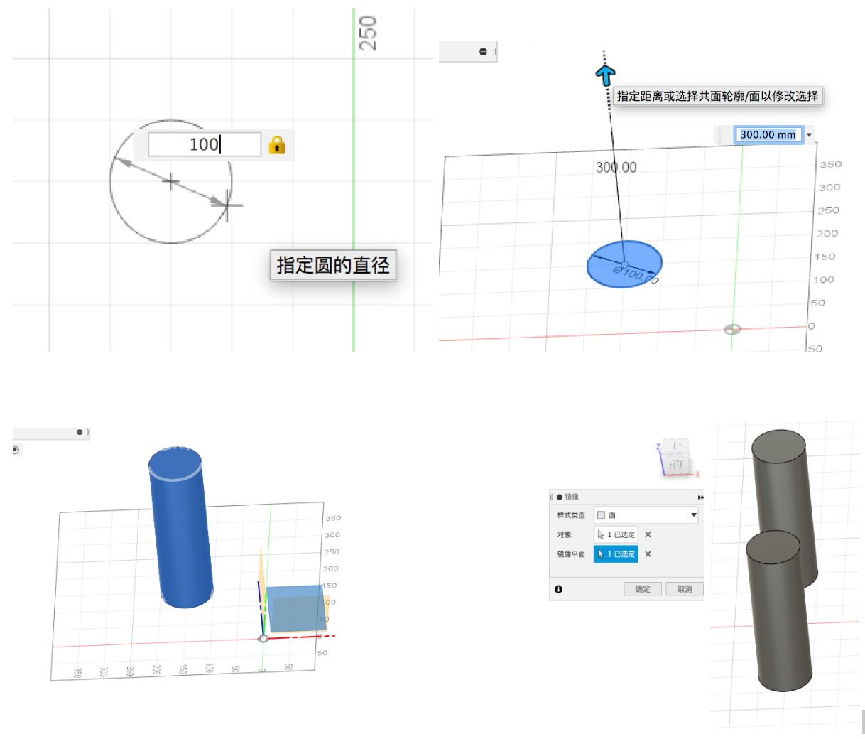
Change the operation command to “cut”. Then we will create two symmetric holes on the ROV main body.
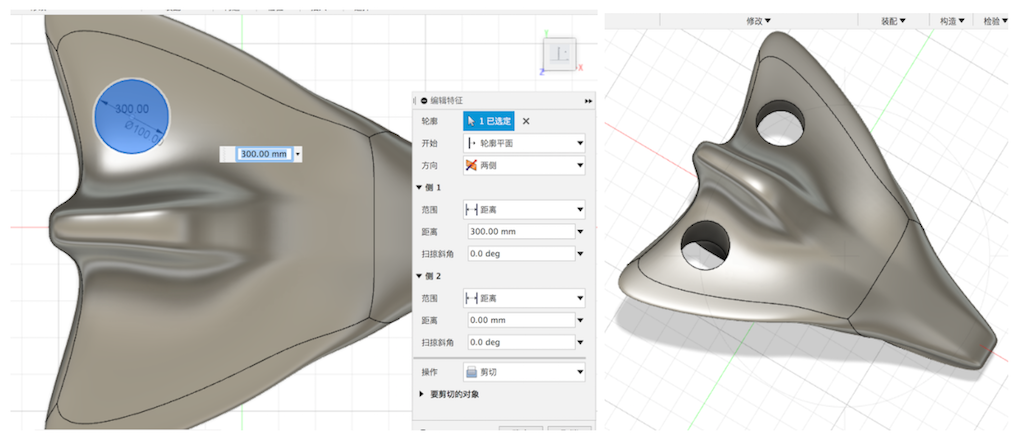
Doing the same job to the top of the object from the front view.At last, we made three holes for motors.
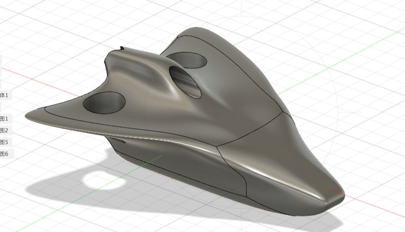
Save the document to STL file.
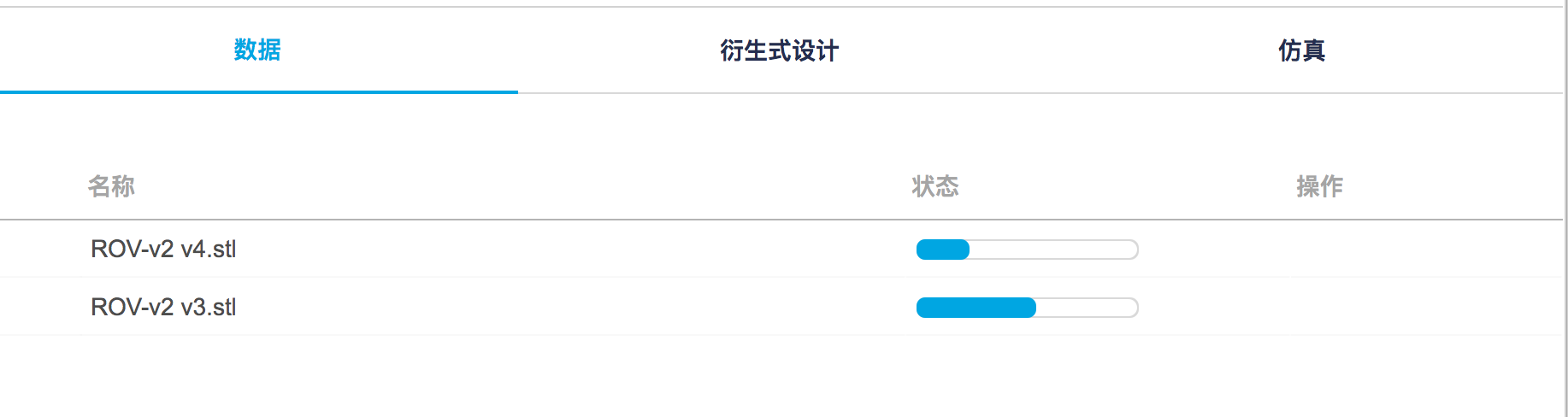
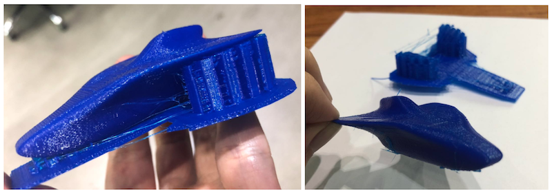
Then I just printed it like the before operation. This week due to the time I just printed the first version module without the motor holes. Next, I will do much work on the prototype of the ROV. Change the ROV’s shape to more reasonable for the water and gravity.
3D Scaninng
After that, I’m going to work on 3D scanning. Actually, there is no 3D scanner here in our lab. I used one 3D scanner in our corporate lab in Guangzhou. Due to the Coronavirus-19 in China, transportation is not very convenient so I couldn’t go there using their equipment. But could show a short video that I made before.
What I found this week as a plan B is studying a 3D scanning software for a cellphone called Qlone.
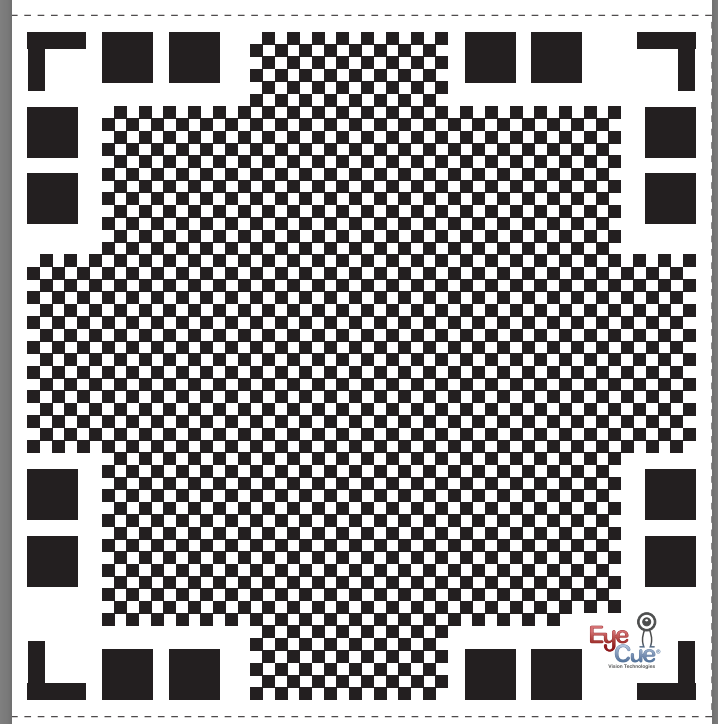
Before the scanning, we need to download the Qlone map, then put the map under the object that you want to scan. We can scale the map match to our product size.
What I’m done is in the next videos.
As you see the module’s quality is not very well. I thought the problem depends on how stable that you operate your phone. That should be quite smooth. Some other issues I suppose that link to camera and light.