7. Computer-Controlled Machining
This week I’m going to design some projects that are made of wood and use the CNC machine to make it. Before this week’s project, I’m supposed that I need to do some exercises. This way I can better complete the tasks so that I do not make some mistakes during the design process.
Assignment
Group assignment
+ test runout, alignment, speeds, feeds, and toolpaths for your machine
Individual assignment
+ make (design+mill+assemble) something big
Due to the problem to the CNC-Shopbot in our laboratory, I have no way to actually operate the CNC equipment. I have tried to solve the corresponding problems with my instructor, but in the end, we have not been able to repair the shopbot, so I cannot produce the related assignments for the time being.
Exercises for design A
At first, I want to try to make some samples of combine parts.
Although some of these exercises are very simple, but during the design process, I practiced a lot for the software using skills.
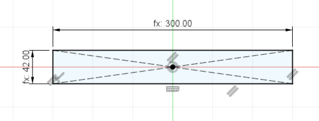
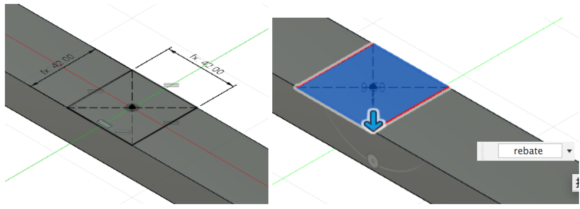
In this exercise, I will try to design a “crossing” groove connection to join two pieces of wood together.
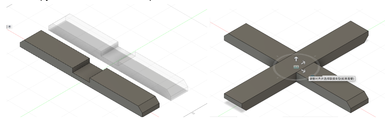
Next, I tried to make another “crossing” sample. I created one part then copy it and paste the other one.
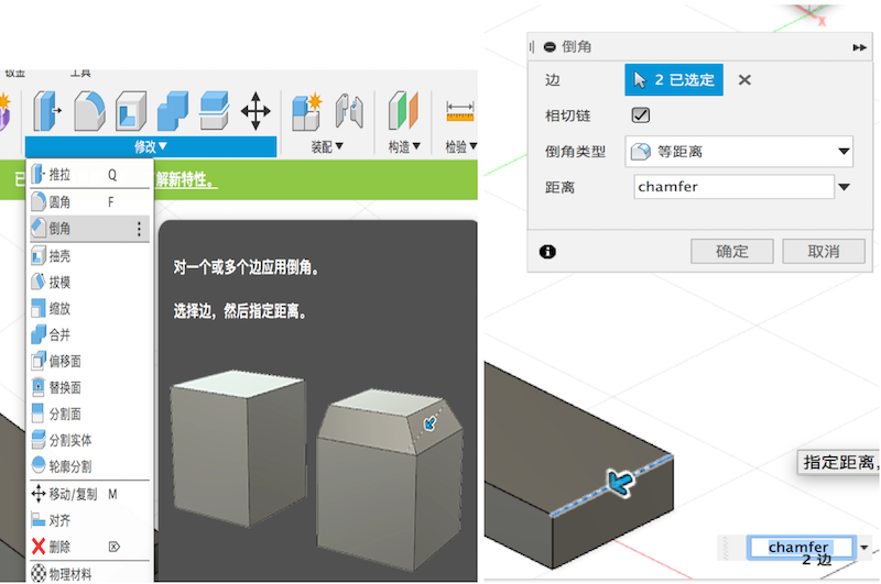
And I tried to make a chamfer for these parts.
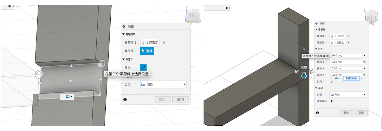
Then copy it and make two same parts. And use the “Joint” command to connect them.
Exercises for design B
Next, I made one more difficult project. I found some tutorials from youtube and learned how to make a computer stand.
This time I will use the “parameter” command could help me to change the design size easily.
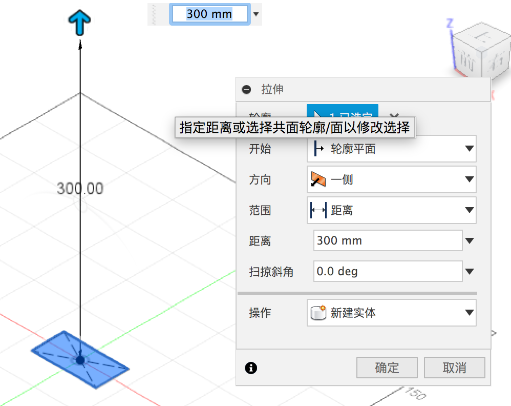
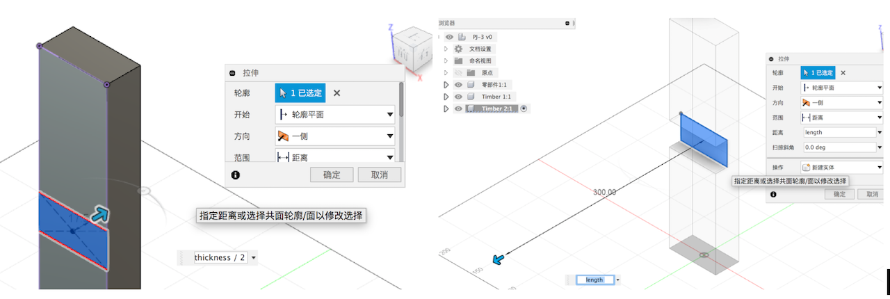
Firstly, make a stand leg’s original sketch. Use the line to draw the right view outline of the leg. And set the length size and the relative angle.
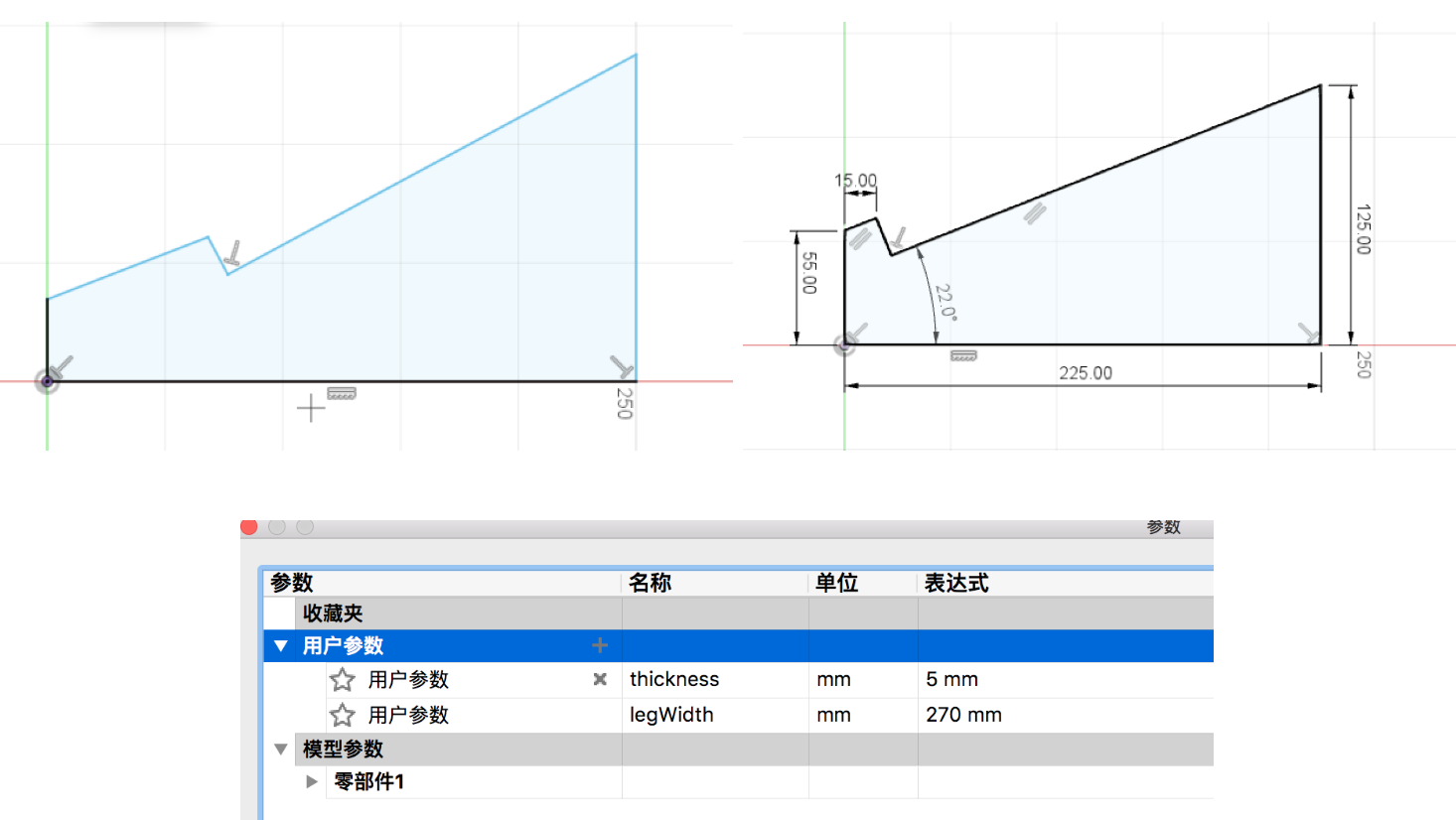
Extrude this leg sketch and make the every angle fillet. Because we must not want to be scratched by its angle and sides during using it.
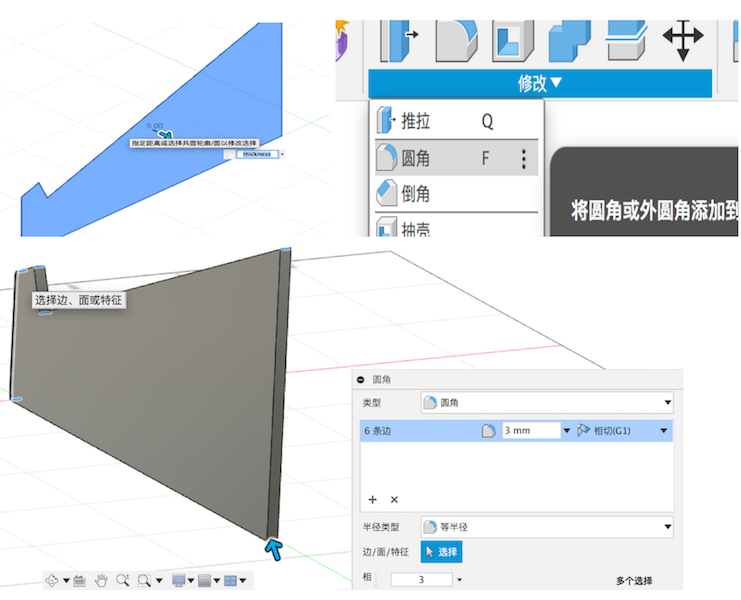
Then copy the leg and let them as a right distance away from each other. Great I’ve finished the base of the design. I will use these objects as a reference to complete the next work.
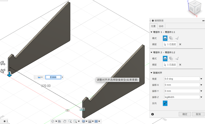
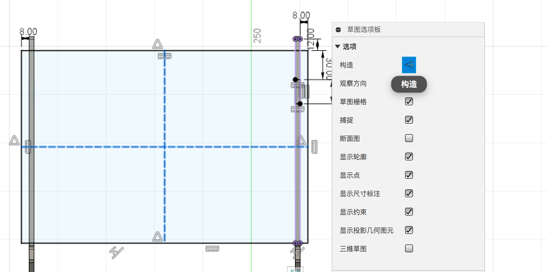
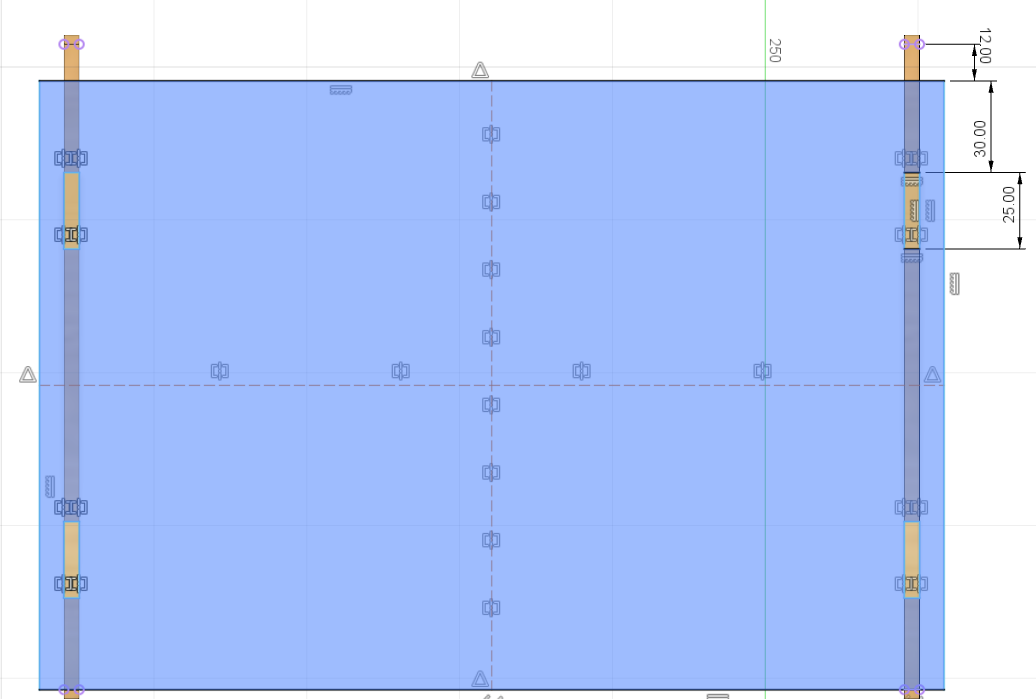
Create a new plane for the top part. And draw a rectangle and set the sides.
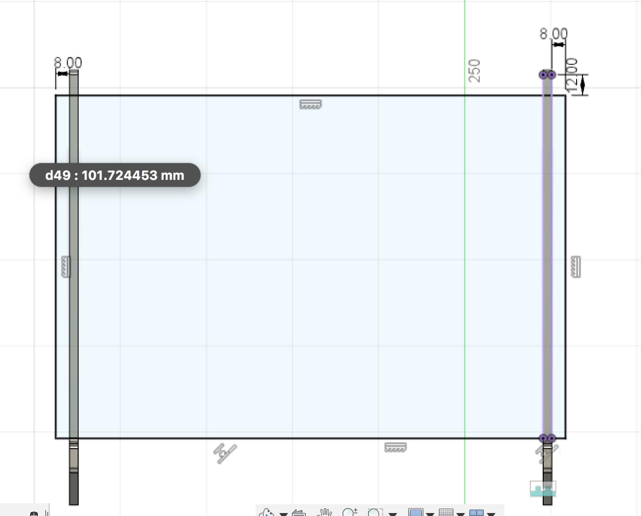
I deigned one small rectangle for the top as a joint hole combines with the legs.
And use the mirror command to create three more similar holes on the top part.
Extrude the top sketch at the thickness.
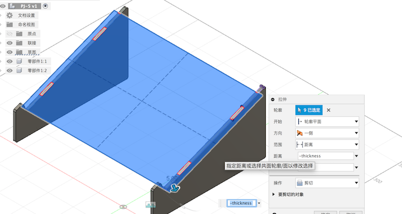
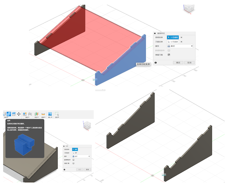
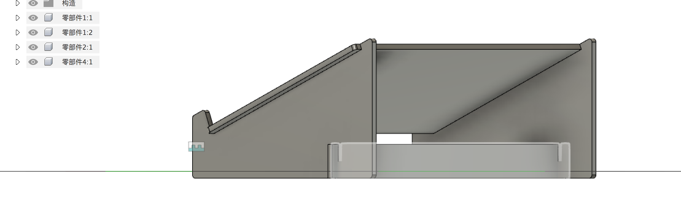
Through the “combine” command to cut the legs objects. Set the legs as the target and the top part is the cut tool. Thus we will get the leg parts which include the joint construction like the below images show.
Now I have completed half of the work. Next, I was going to design the bottom support structure.
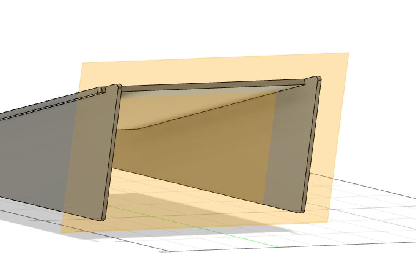
Make a new plane for the bottom parts. Refer to vertical legs plane. These design rules are very similar to the top parts.
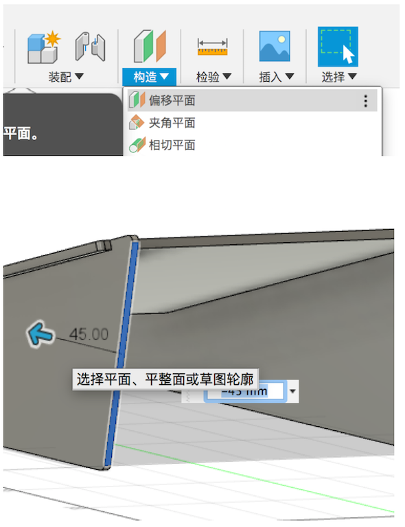
Offset the plane to the right place.
In this step, I used the “project/include” command. When we need to position the plane, this command is very important.
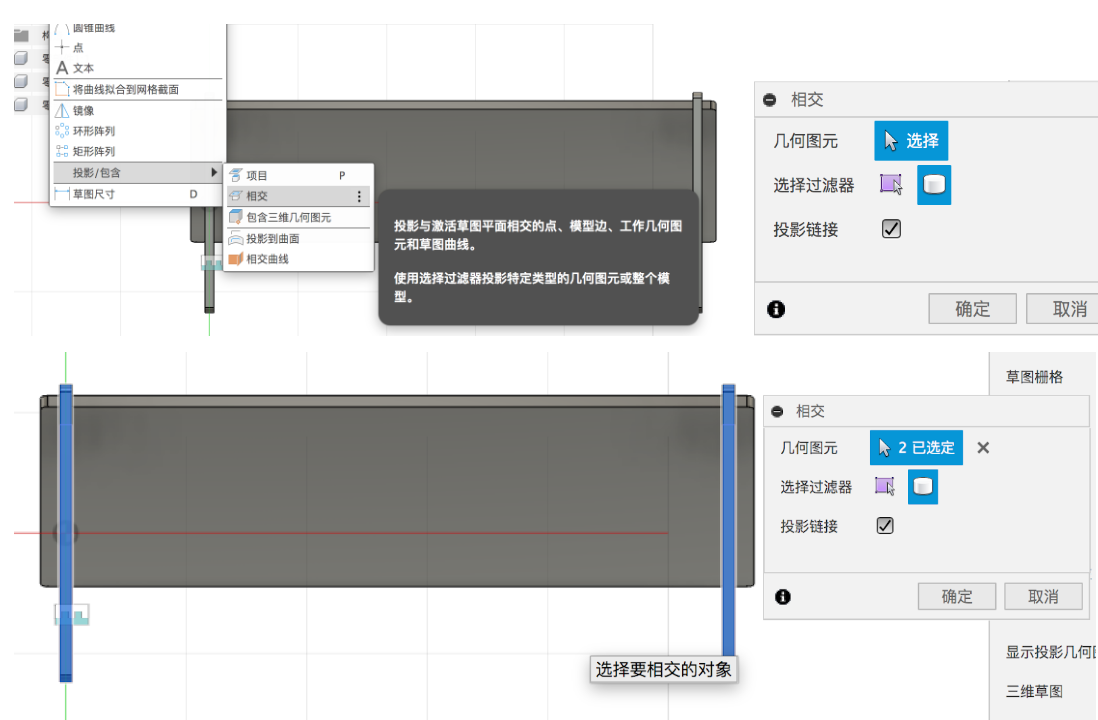
Create the new support sketch on this plane.
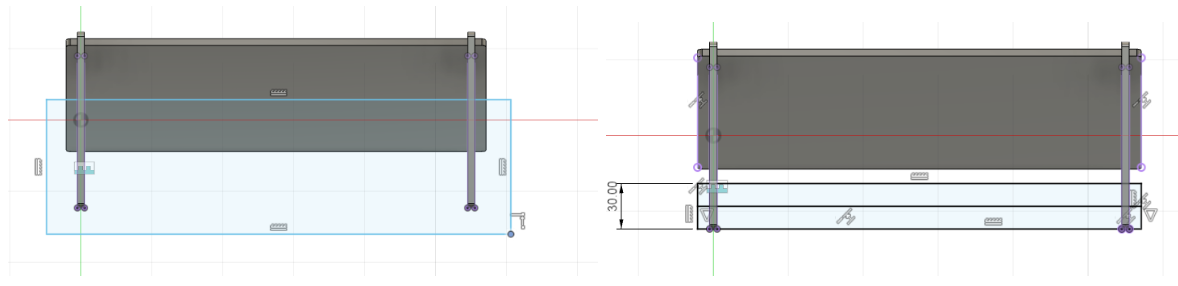
Extrude the support sketch at the thickness.
To find the middle plane between the legs and use the mirror command to copy the support part that I’ve made. Then I’ve got two support parts.
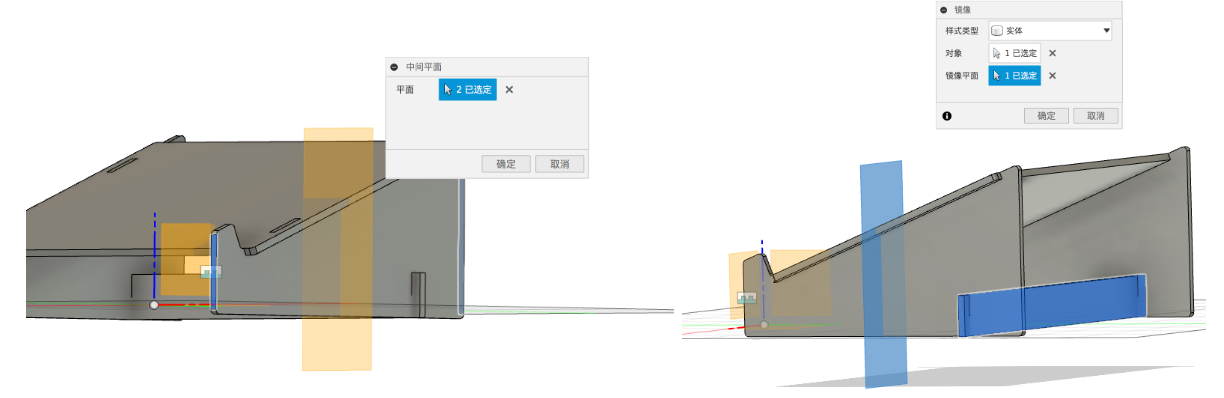
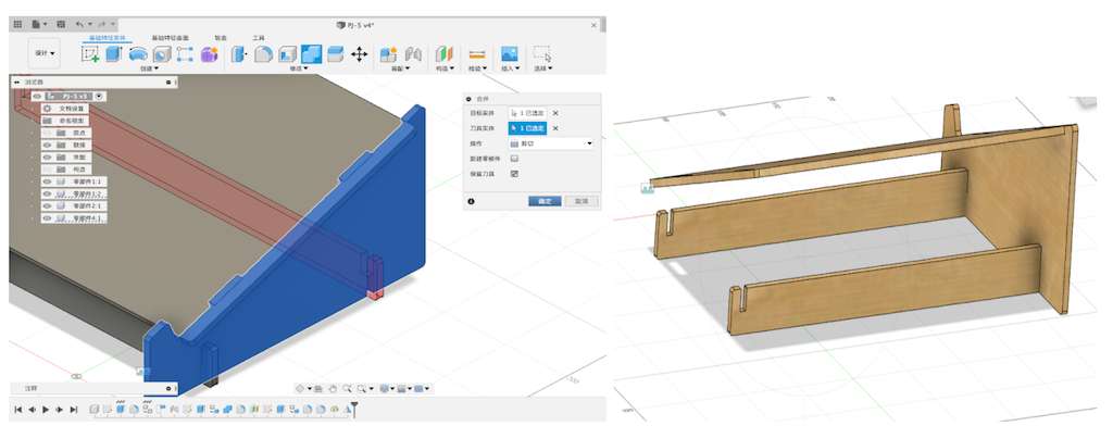
Create a joint shape using “combine” command. And we could add the appearance to the object.
Asssingment design
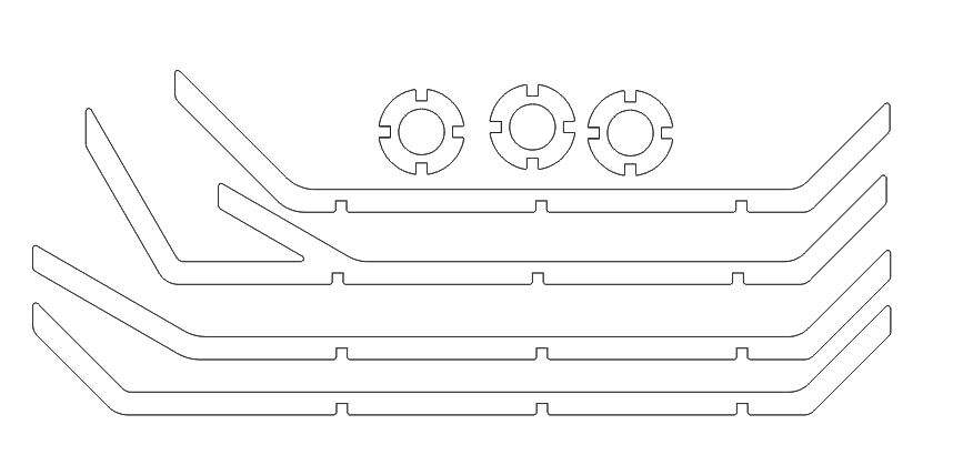
At last, I designed the week assignment that something big. I was going to make a tree hanger with 18mm or 19mm thickness wood. I planed to make four parts as the “tree body” and make three center joint objects to fix the whole hanger.
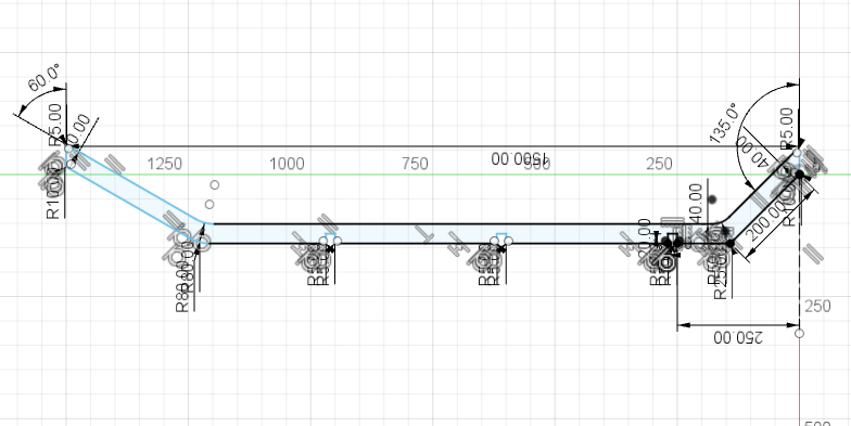
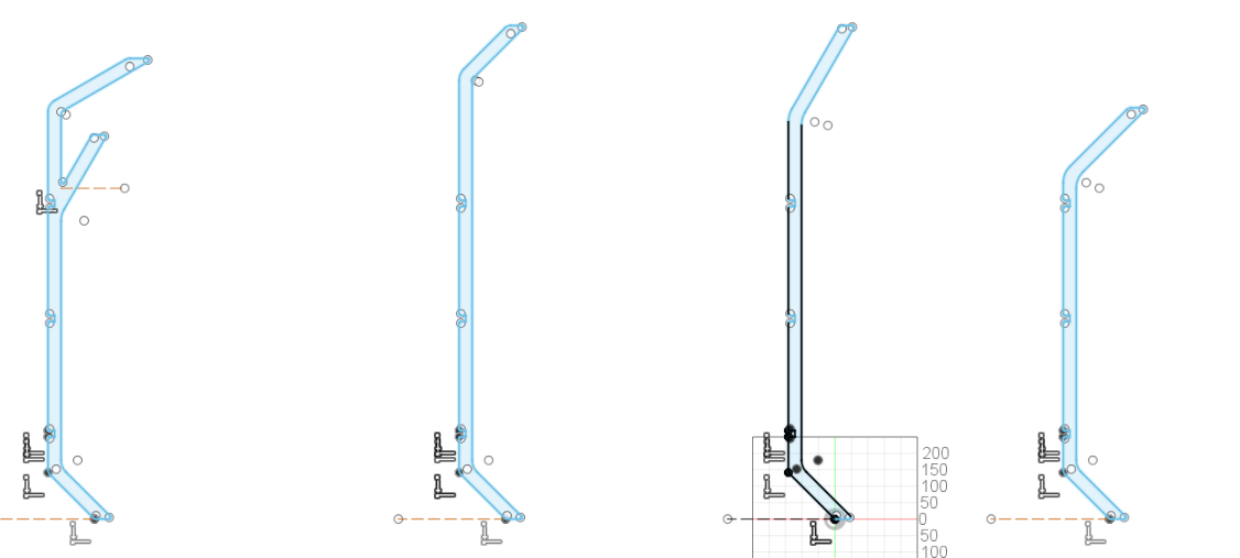
My idea is to make one of the body parts. And copy three more sketched their bottom of the sketch be the same. Just change the top parts of them. Change the height and the angle and to draw them like a tree.
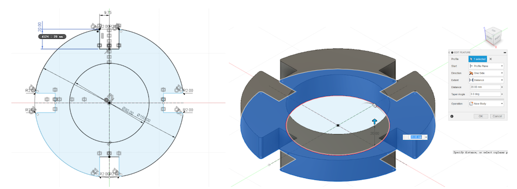
Next, I made the center joint objects. Actually what I thought the three objects are the same design. So I just need to make one sketch. The shape should be like a ring but include four grooves. Thus the center joint parts were able to be combined with the body parts.
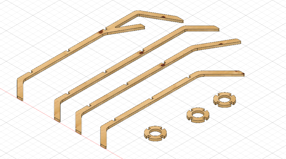
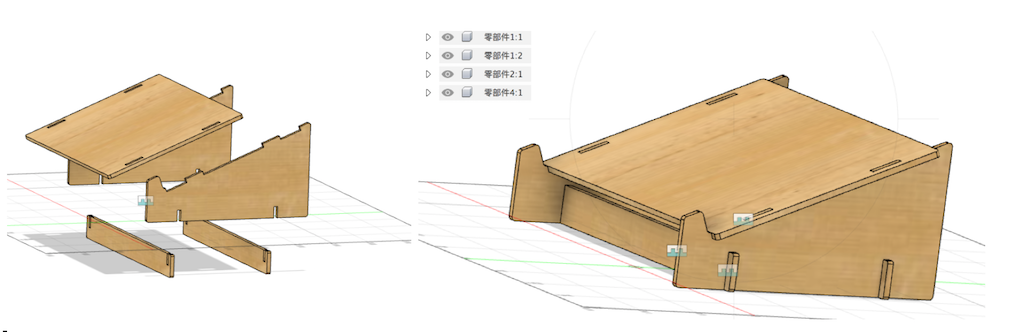
Finally, I finished all the parts design. Then I will assemble to the tree hanger.
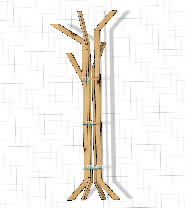
I’ve exported the design file to DXF. I really want to make them to the physical project.