Assignment 10 - Embedded Networking and Communications
The Group Assignment for this week is to send a message between two projects.
The group assignment is done by Ting Kok Eng, Noel Kristian, Yeo Gau Siong and Lucas Lim.
The task is to send a message between 2 projects. 2 projects according to Fab Academy 2020 Assignments and Assessment webpage, is defined as between any combination of boards, computers and/or mobile devices. After discussion, our group has decided to explore a few common networking and communication protocols such as:
- I2C (inter integrated circuit)
- SPI (serial peripheral interface)
- UART (universal asynchronous receiver transmitter) and
- BLuetooth
As for the individual assignment, all of us have tried using the I2C protocol, hence of the group assignment, the team decided to focus on UART, SPI and Bluetooth communication protocols.
1. Introduction
To understand more about communications between electronic devices, the team did some internet searches and this article published by the Electronics and Communication Engineering department of the Siddharth Institute of Engineering and Technology is particularly easy to understand. The team's learning from this article is summarised below
Communication Protocols
Just like communications between humans, for electronic devices to communicate with each other, both sides need to speak the same language. In electronics, these languages are termed communication protocols. A Protocol is a set of rules agreed by both the sender and receiver on:
- How the data is packed?
- How many bits constitute a character?
- When does the data transmission begins and ends?
Examples of communication protocols are SPI, I2C, UART, USB, ethernet, Bluetooth and Wifi.
SPI, I2C, and UART are much slower compared to the rest, however, they are much simpler and require lesser hardware and system resources, which make them ideal for communication between microcontrollers and sensors where high speed data transfers are usually not required.
Parallel & Serial Transmission
Data communications can be classified as Parallel and Serial as shown in the image below.
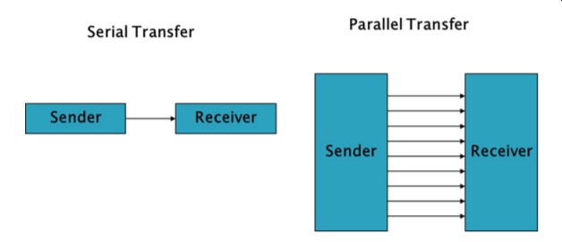
Parallel Communication
In parallel communication, all the bits of data are transmitted simultaneously on separate communication lines. Transmission is fast however parallel coomunication is costly as because to transmit n bit, n wires or lines are required. For this reason, they are usually use for shorter distance transmission such as in printers and hardddisks.
Serial Communication
For serial communication, the data bits are transmitted serially bit by bit on single communication lines. They are hence less costly and can be used for long distance transmission such as in telephone communications. Serial communication uses two methods:
- Asynchronous transmission
- Synchronous transmission
Synchronous & Asynchronous Transmission
In synchronous communication, data is transmitting and receiving in a continuous stream at a constant rate. Synchronous communication requires the clock of the transmitting device and the receiving device to be synchronized. In most of the systems, transmission and reception of data occurs with same frequency. Examples of synchronous communication are: I2C, SPI etc. In the case of asynchronous communication, the transmission of data requires no clock signal and data transfer occurs intermittently rather than in a steady stream. Handshake signals between the transmitter and receiver are hence important in asynchronous communications. Examples of asynchronous communication are UART and USB.
Baud Rate Concepts
Data transfer rate in serial communication is measured in terms of bits per second (bps) also known as Baud Rate. Baud Rate and bps can be used inter changeably with respect to UART. Generally baud rates of SCI are 1200, 2400, 4800, 9600, 19,200 etc. To transfer 250,000 bits at a baud rate of 9600, the time required is 250000/9600 = 26.04 seconds (27 seconds).
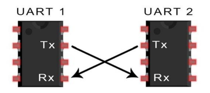
UART Protocol
In UART communication, two UARTs communicate directly with each other. The transmitting UART converts parallel data into serial form, transmits it in serial to the receiving UART, which then converts the serial data back into parallel data for the receiving device. Only two wires are needed to transmit data between two UARTs. Data flows from the Tx pin of the transmitting UART to the Rx pin of the receiving UART: UARTs transmit data asynchronously, which means that there is no clock signal to synchronize the output of bits from the transmitting UART to the sampling of bits by the receiving UART. Instead of a clock signal, the transmitting UART adds start and stop bits to the data packet being transferred. These bits define the beginning and end of the data packet so the receiving UART knows when to start reading the bits. When the receiving UART detects a start bit, it starts to read the incoming bits at a specific baud rate. Both UARTs must operate at about the same baud rates differring by not more than 10% before the timing of bits gets too far off.
Hands-on with UART communication protocol
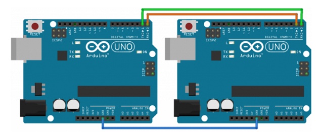
In this part, 2 arduino uno boards will be used where the UART serial communication will be used. One arduino board will act as a sender that will transmit data and the other board will act as a receiver to receive the data.
The circuit connection is shown in the below figures:
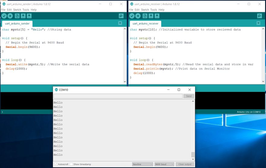
There are 2 arduino sketch codes. The first one is for the sender board. In the sender code we first initialize a string with data "Hello". In setup, the Serial Monitor is begun at 9600 Baud. In the loop, send the data to receiver board using Serial.write.
to download the sender Arduino sketch code
For the receiver Arduino Board code, we first initialize a blank string to store serial received data. In the setup, the serial monitor is begun at 9600 Baud. In the loop, the received data from sender Arduino is read and stored using Serial.readBytes.
to download the receiver Arduino sketch code
After uploading the sender code to the sender board and receiver code to the receiver board, then we can connect the 2 boards as per circuit connection above. The sender board will transmit "Hello" through its TX pin and this will be received by the receiver board via its RX pin. On the receiver board COM port (Serial Monitor in IDE), the "Hello" will be shown.
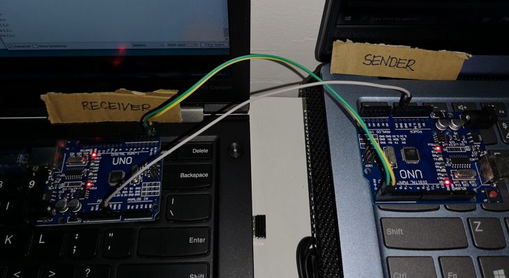
Below is the short video when the 2 boards communicates via UART.
The board on the right is the sender, while the board on the left is the receiver. You can see that the TX and RX led on both boards were blinking throughout and the serial monitor for the receiver board showed the "Hello" message sent by sender board.
SPI Protocol
SPI is a common communication protocol used by many devices such as SD card modules, RFID card reader modules, and 2.4 GHz wireless transmitter/receivers. The benefit of SPI is the fact that data can be transferred without interruption. Any number of bits can be sent or received in a continuous stream. With I2C and UART, data is sent in packets, limited to a specific number of bits. Start and stop conditions define the beginning and end of each packet, so the data is interrupted during transmission. Devices communicating via SPI are in a master-slave relationship. The master is the controlling device, while the slave takes instruction from the master. The simplest configuration of SPI is a single master, single slave system, but one master can control more than one slave. While UART need two wires, for SPI, 4 wires are required, namely:
- MOSI (Master Output/Slave Input) - Line for the master to send data to the slave
- MISO (Master Input/Slave Output) - Line for the slave to send data to the master
- SCLK (Clock) - Line for the clock signal
- SS/CS (Slave Select/Chip Select) - Line for the master to select which slave to send data to
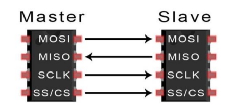
One-to-One
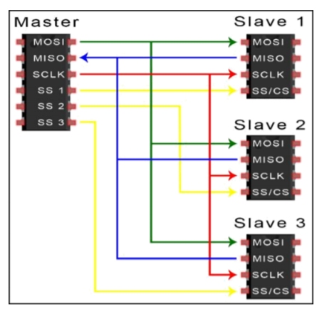
One-to-Many
Compared to I2C, SPI does not need complicated slave addressing system, the data transfer rate is also faster as data can be sent and received at the same time via dedicated MISO and MOSI lines. However, as SPI does not require start and stop bits (unlike in UART), there is no acknowledgement that the data has been successfully received (unlike I2C) nor any form of error checking like the parity bit in UART.
Hands-on with SPI communication protocol
The SPI pins on the Arduino UNO boards are 10 to 13 and also the ISCP header located at the right as shown in the image below (in the red box)
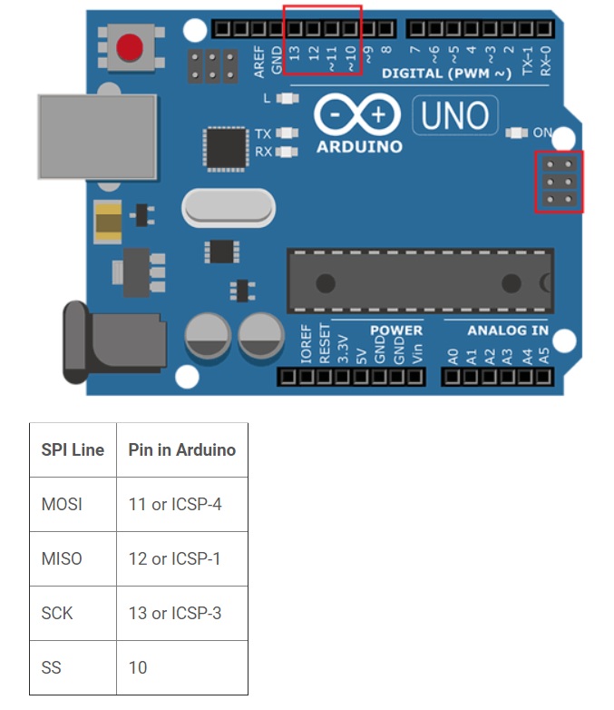
Image from Circuitdigest.com
Just like I2C, to use SPI in Arduino IDE, the dedicated library SPI.h must be added at the beginning of the Sketch program. To initialize the SPI bus, the SPI.begin command must be added at the void setup section to set the data direction properly.
The next SPI specific syntax is the SPI.setClockDivider(divider) command that is used to set the SPI clock divider relative to the system clock. The available dividers are as follows:
- SPI_CLOCK_DIV2
- SPI_CLOCK_DIV4
- SPI_CLOCK_DIV8
- SPI_CLOCK_DIV16
- SPI_CLOCK_DIV32
- SPI_CLOCK_DIV64
- SPI_CLOCK_DIV128
SPI.attachInterrupt(handler) is used when a slave device receives data from the master and the SPI.transfer(val) command is used to simultaneous send and receive the data between master and slave.
There are several tutorials on this topic available on the internet. The lesson by Robert Paz, titled Hands On Arduino 5B: Arduino to Arduino SPI Comm. is particularly clearly and easy to understand. For the hands-on test, the team tried the example by Robert Paz as well as the example on cirrcuitdigest.com but somehow for both examples, the team cannot get the setup to function as shown in the tutorials. The Sketch programs and the syntax used are consistent with the many tutorials that the team read and also all the programs can be compiled and uploaded onto the UNO boards. We suspected maybe one or both of the UNO boards is/are damaged. We tried another example on Arduino-er.blogspot.com and managed to get the setup working, ruling out that the UNO boards are damaged. For this example, the Sketch program is vastly different from most of the tutorials available. For example, the SPI.setClockDivider(divider) command is not used, and data direction registers (e,g, DDRB) are used for the Slave program instead on using the SPI.h library. As the team is very new to programming languages, we decided to move on and revisit this issue when schedule permits.
The master and slave Sketch programs for the working example are as below:
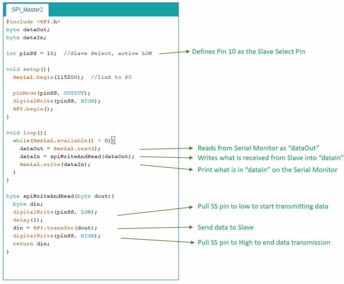
Sketch program for Master Device
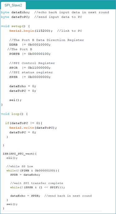
Sketch program for Slave Device
In this example, any data receives by the Master Arduino from Serial (PC keyboard input) will be sent to Slave Arduino using SPI. The Slave Arduino will echo what it receives and sends back to the Master Arduino which will display it on the serial monitor(PC). The result is shown in the video below:
to download the sketch file for master deviceto download the sketch file for slave device
Bluetooth
Bluetooth is a short-range communication technology that is widely used in smartphones and many other fixed as well as mobile devices, for data transfer and building personal area networks. It operates in the 2.4GHz ISM frequency band and uses frequency hopping spread spectrum technique. Bluetooth is a packet-based protocol with a master-slave structure. One master may communicate with upto 7 slaves in a piconet. Two or more piconets can be connected to form a bigger network, called a scatternet.
Bluetooth is widely used in applications like handsfree headset, phone-to-phone data transfer, cable-free connection between PC and I/O modules like mouse, keyboard, printer etc. Bluetooth in its new avatar as Bluetooth Low Energy (BLE), is expected to be a key technology in near future for wearable devices that will connect to the IoT, probably through the smartphones and other such options.
Bluetooth BLE is meant to provide low-cost and low-power consumption while maintaining the same range as Bluetooth.
Hands-on with Bluetooth communication protocol
For the hands-on part, the demostration found on Evothings.com was referred to. A GUI app running on Android mobile phone is developed. The app allows the phone to send commands via Bluetooth to an Arduino UNO, which is connected to a bluetooth module (AT-09 BLE module), to turn on or off a LED.
The software used are:
- Evothings Workbench; this is a desktop application for running apps on mobile devices
- Evothings Viewer app; this is ideal for developing IoT mobile apps as it is easy to use
- Audrino IDE
The hardware used are:
- 1 x AT-09 Bluetooth BLE module
- 1 x Arduino Uno
- 1 x Red LED
- 1 x 220 ohm resistor
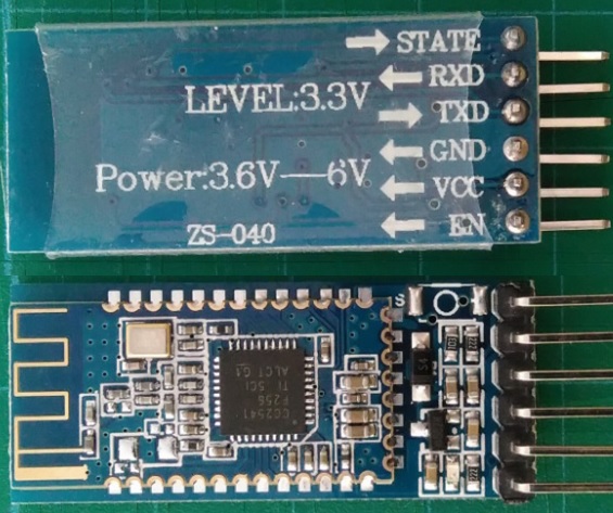
Back & Front view of AT-09 BLE module
Connecting the circuit
- Connect 3.3V of Arduino to the VCC of AT-09
- Connect GND of Arduino to the GND of AT-09
- Connect D8 of Arduino to RX of AT-09
- Connect D7 of Arduino to TX of AT-09
- Connect D13 of Arduino to the Anode of LED along with a 220 ohm resistor
- Connect the opposite end of the resistor to GND of Arduino
- Connect the cathode of LED with the GND of Arduino
- Connect the USB between Arduino to a computer
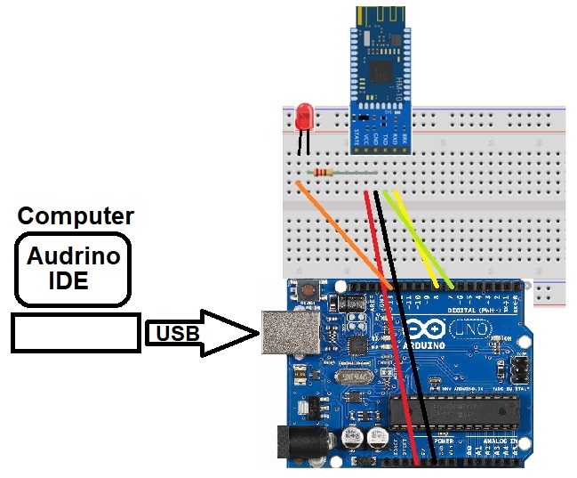
Wire Connection
Sketch Program
For this activity, the Arduino Sketch program written by Hammad Tariq was used. The program was downloaded from his Github repository and shown below:
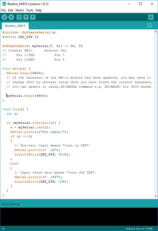
Hammad's Sketch Program
Install Evothings Softwares
Evothing Workbench is to be installed on the PC and can be downloaded from Evothings.com. This software enables the PC to communicate with the mobile phone via Bluetooth. Installation is straightforward following the onscreen instructions such as getting to get a Cloud key to complete the installation. For the mobile phone, the Evothings Viewer app can be downloaded from the Appstore (iOS, Android)
Establish Connections
To link the phone to the PC, simply get a connection key from the Evothings Workbench by clicking on the Get Key button and input into the Evothings Viewer app. The PC and the mobile phone can now be connected by tapping the connect button on the mobile App.
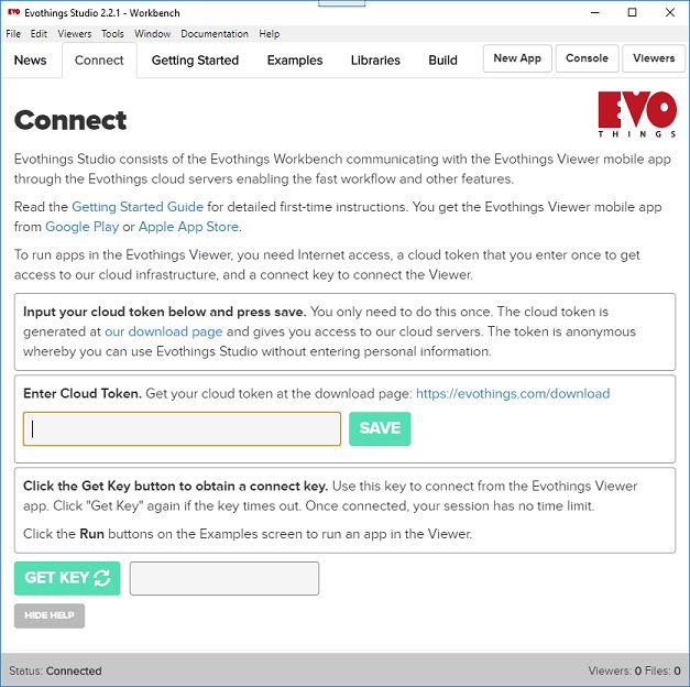
Get Connection Key from the PC
To check that connection between the mobile phone and the PC is established, the Hello World example is run by going to the Examples tab and click the Run button. One thing great about Evothing Workbench is that the index.html files for all the examples can be modified or customised to suit the users' needs.

Coonection Established
To establish connection between the Arduino (via the bluetooth module) and the mobile, the Bluetooth BLE module must first be identified. This can be done by running the BLE Scan program found under the Examples tab.
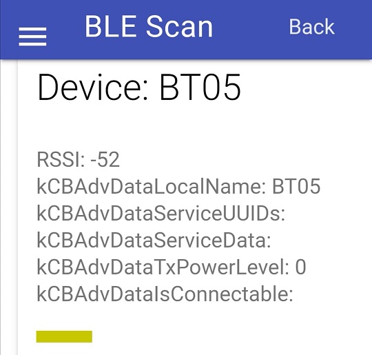
BLE module is identified as BT05
Customising Mobile App
For the mobile phone GUI, the mobile app is written by Hammad Tariq is downloaded from his Github respository. After downloading, the index.html from the hm10-arduino-ble example is dragged and dropped into the My Apps tab on Evothings Workbench.
Running this example will open an app on the mobile. This app code is written to be used with Evothings Studio and using this example app code, one can easily control an LED with the mobile phone via the AT-09 Bluetooth BLE module connected to Arduino UNO. It is important to Open the Index.html file with a code editor (ATOM for this case), to check that under the app.connect function() section that BT05 is specified.
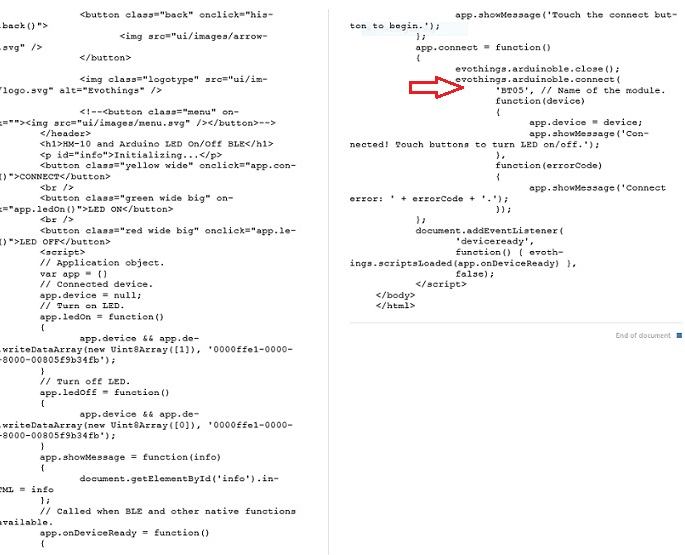
Section of the code showing "BT-05" is connected
After checking, the example can be run from the PC. This will load the example on the mobile phone Evothings Viewer app. To establish Bluetooth connection the Connect button is first pressed. Once connected, the ON/OFF buttons can be used to toggle the LED On/Off. The video below shows the operating of the app
to download the sketch file for Bluetooth communication