Assignment 1
This website contains the documentation and write-up for Group Assignment 1 - Computer Controlled Cutting.
For the
characterization, 3 different materials namely, corrugated
cardboard, clear acrylic and plywood were used.
a squares each measuring 25.0 mm by 25.0 mm were first
created on CorelDraw X8.
The line colors
for the four squares were set as Red, Green, Blue and
Magenta and the line thickness was as “hairline” to enable
the cutting mode. Using
4 line colors allow 4 different combinations of Power, Speed
and Frequency (PPI) to be set so that each square can be cut
with a different set of parameters. This will hasten the
characterization process substantially.

Corrugated Cardboard
The
first material used was a 3.5 mm thick corrugated cardboard.
A group of four squares were cut and the specimens were
examined carefully for cut marks on both sides of the
materials. Based on the results obtained, the parameters
were adjusted and a new group of 4 squares are cut.

4 groups of 4 were run.The first three groups of
parameters did not managed to cut the squares. For the
fourth group, the last 2 settings were able to produce
nice clean cut-out on the cardboard.
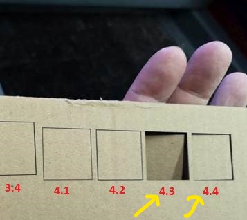
The settings and
results are tabulated as follows:
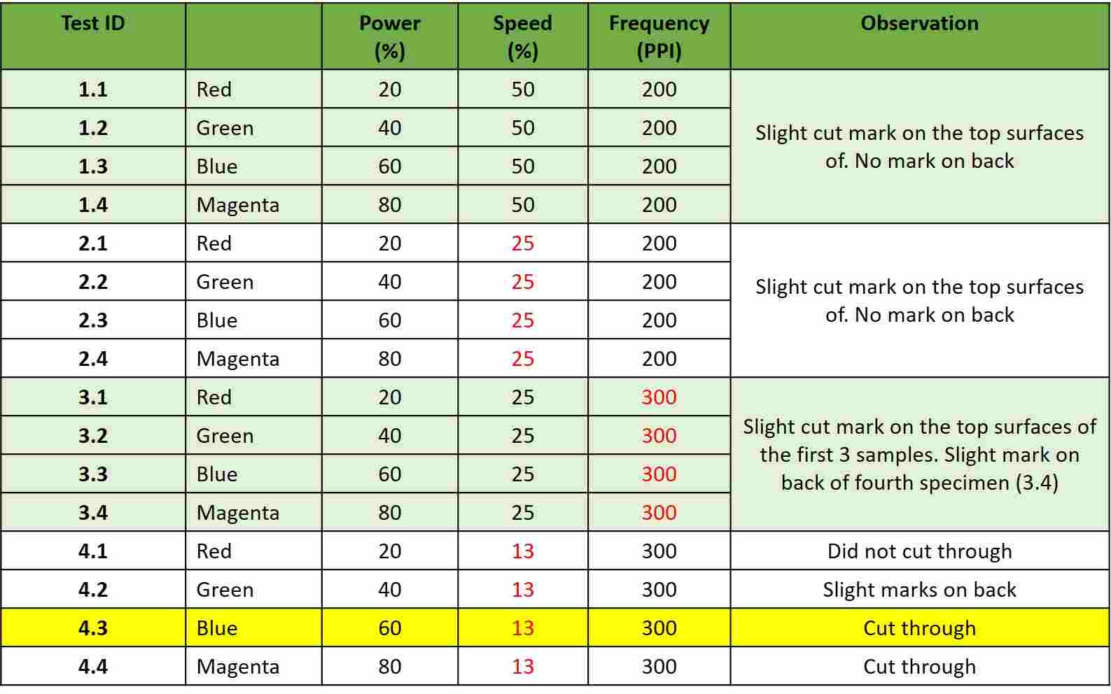
Table 1: Test Details and Results for
3.5 mm Corrugated Cardboard
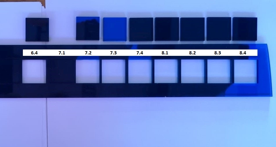
Clear Blue Acrylic
The next material
tested was a 2.9 mm clear blue acrylic sheet. Similar test
method as above was adopted. A total of 16 squares were also
cut in groups of 4 and the settings as well as results are
tabulated as follows:
Table
2: Test Details and Results for 2.9 mm Clear Blue Acrylic
Sheet

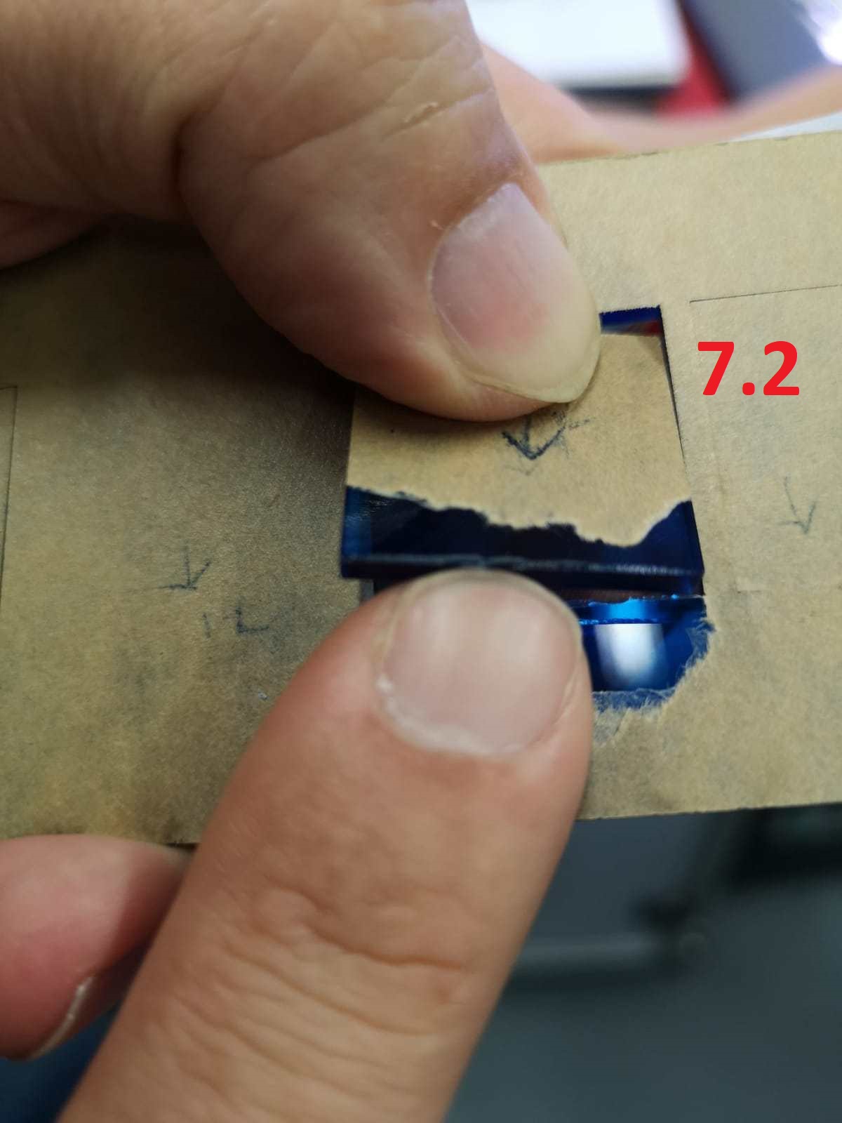
For the third set onward, the laser can
partially (see image below) or wholly cut through the
acrylic sheet.
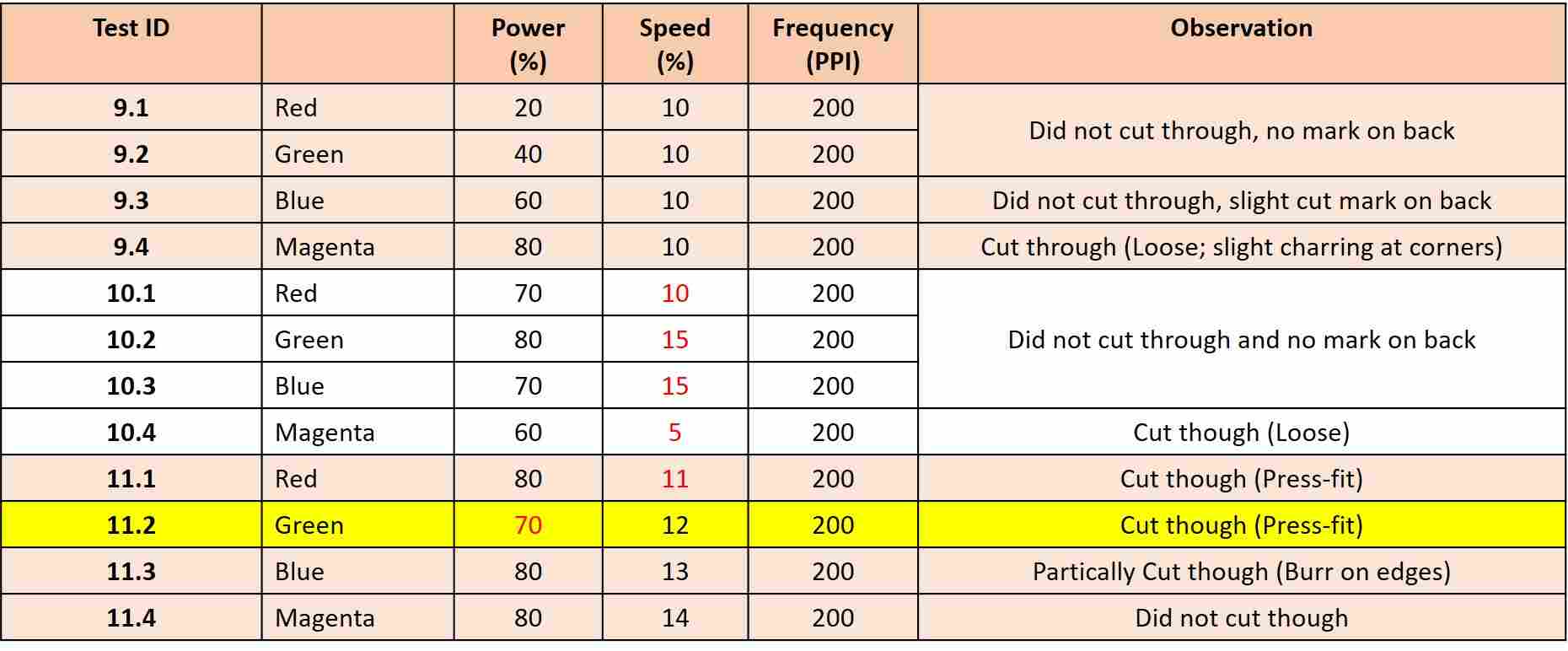
Plywood
The third material tested was a 2.4 mm plywood sheet. A total of 12 squares were cut in groups of 4 and the results are tabulated as follows. For Plywood, there are several specimens exhibiting partially cut. Uneven material thickness is believed to be the cause.
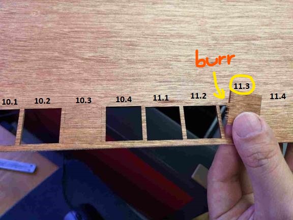
Table 3: Test Details and Results
for 2.4 mm Plywood
The summary of
the optimum settings for the three materials are as below:

After completing
the characterization, the next step is to determine the
kerf for each material.
Table
4: Kerfs for different materials

(All dimensions
in mm)
During
the measurement, we observed that the thickness of the
corrugated cardboard is very inconsistent, as such, the
team decided to use plywood (2.4 mm thickness) for our
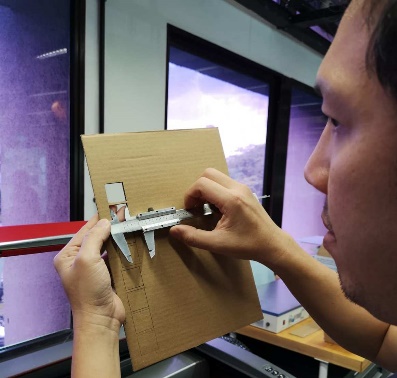
construction kit. We decided to make a test gauge to
determine the best fit. The test gauge was a comb,
where the cut-off width is varied from the thickness of
material and gradually decreases by 0.05 mm. When the
cut-off was set at 2.3 mm (shown in the below picture),
the plywood (2.4 mm thickness) can fit tightly into the
cut-off part, hence the kerf is 0.5 x (2.40-2.30) = 0.05
mm. The result showed that the kerf is actually 0.05 mm,
quite different from our test finding earlier of 0.01 mm
and 0.02 mm. We used 0.05 mm for our parametric press-fit
construction kit and the results were tight fit.

We decided to
use a kerf of 0.05mm for our laser cutting.