Assignment 8 - Output Devices
The Group Assignment for this week is to measure the power consumption of an output device.
The group assignment is done by Ting Kok Eng, Noel Kristian and Yeo Gau Siong. As SP Fablab is closed due to Covid-19, we have no access to any power supply, hence we decided to measure the power consumption from a simple DC motor powered by an USB cable. 2 multimeters were used to measure currents and voltages.
DC power measurement is simple as the equation is simply
In AC systems, multiplying Voltage by Current gives the apparent power. To get true or real power, a power factor (PF) must be introduced and the equation becomes:
In Week 6 Electronics Design, we learnt about current and voltage measurement. Ammeter must be connected in series with the load while voltmeter is connected in parallel with the load, which in our case is a DC motor.
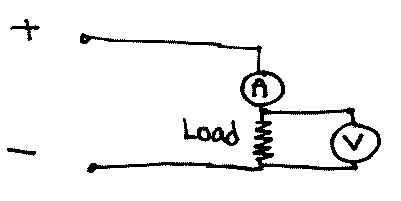
With this connection, we are able to get both the volatge across the load as well as the current going through the load. From the video, the voltage is 5.05V while the current is about 28.3mA (or 0.0283A). Hence the power consumption of this simple DC motor is 0.143 watt (W).
Internal Resistance of the multimeter
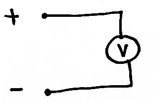
The internal resistance of the multimeter is typically in the MΩ range. Hence to measure the internal resistance of the meter, an external resistance of comparable resistance must be used. The voltage across the supply source is first measured. In our case, this is 5.05V from an USB port. (refer to image below)
Next, a resistor is connected in series to the multimeter and connected to the supply source. (refer to image below). As the external resistor is of comparable resistance as the multimeter, a voltage drop will be observed. For this study, a MΩ range resistor is not available thus a LDR placed inside a dark box was used instead. The LDR registered a resistance of 9.55 MΩ. The volatge across the USB cable is 5.05V. When the LDR (still inside the dark box) is connected in series to the multimeter as in the image below, the voltage dropped to 3.28V.
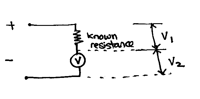
3.28V is V2 (refer to image above. Since the supply voltage is fixed at 5.05V, therefore V1 is 1.77V. The current flowing through the LDR is hence (using I=V/R) 0.185 μA. This current also flows through the multimeter, hence the internal resistance of the multimeter is (using R = V/I) 17.7 MΩ