Assignment 5
Week 7 is on Computer-Controlled Machining. There are 2 assignments; group and individual. The group assignment is documented here
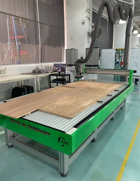
Versatil 2500
The Versatil 2500 large-format CNC milling machine has a working area of 2.5m x 1.25m x 17cm
(A) Terminologies
Before embarking on the group assignment, a basic understanding of some of the common terms used in CNC milling must first be acquired. Through asking our coaches and the colleagues at SP Fablab, the group compiled a glossary of terms that we feel is important as below:
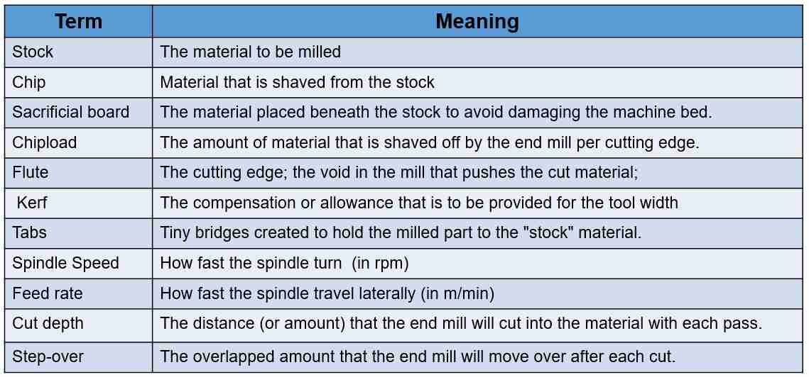
Glossary of terms
(B) Safety
Before we are allowed to operate the machine independently, the team has to attend a safety briefing and demonstration of the machine operation by our coach. The safety pointers and precautions are summarized in the table below
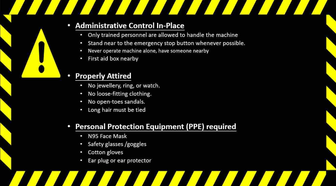
Safety Precautions for handling the CNC machine
(C) Operating Versatil 2500
Versatil 2500 is a CNC (Computer Numerical Control) Milling machine meaning cutting tool will follow a tool path that is preloaded into the machine. Hence before the machine can cut, the tool path file (*.tap) must first be generated and loaded. There are several ways to do this. One way is to import a vector drawing in dxf format into a CAM software such as VCarve to generate the tool path file. Another way is to use the CAM software within Fusion 360 to produce the tool path file. The team tried both methods but unanimously agreed that VCarve Pro is much more intuititive and easier to use.
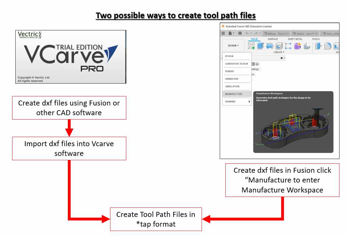
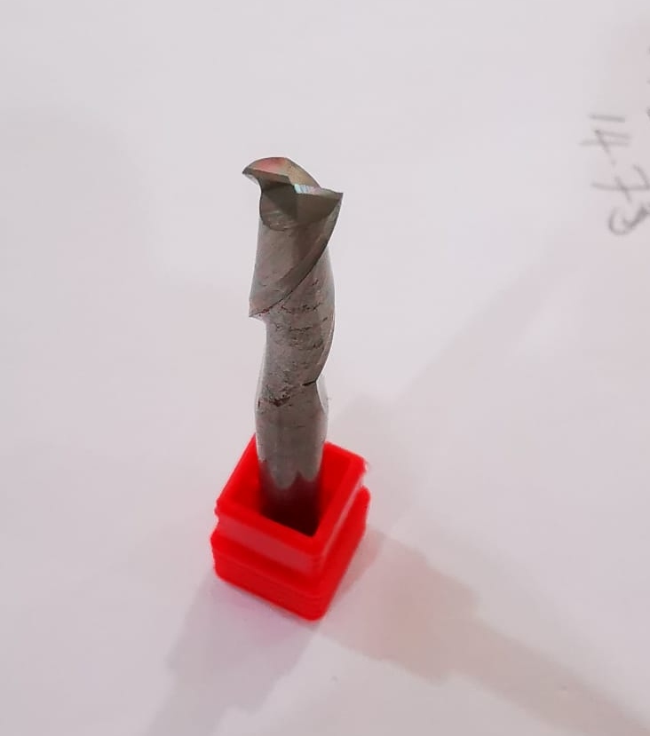
The group hence decided to use VCarve Pro for the group as well as for the individual assignment. Two studies were performed with a 6mm diameter, two-flute, flat end mill cutting tool. The two test were:
- Spindle Speed and Feedrate Relationship
- Kerf and dogbone
(1) Spindle Speed and Feedrate Relationship
Before doing the spindle speed and feedrate test, the group interviewed Mr Walter, our trainer and "CNC man", who gladly explained to us the default settings for the machine as well as the limits of the machine. He adjusted the spindle speed first to 10,000 rpm and then 1550 rpm for us to observe the machine operation at the lower and upper spindle speed limits respectively. At 10,000 rpm, a low, dragging sound was heard will at 15500 rpm, a high pitch noise is produced even through the machine is not cutting anything.
The team hence decided to test 2 spindle speeds. For the feedrate, formula according to NS tool was used:
Feedrate = Number of flutes x Spindle Speed X Chipload.
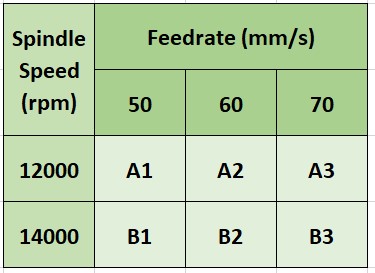
The chipload for this end mill is as recommended by end mill manufacturer, Onsrud, is between 0.001 to 0.01 inches. The team chose midpoint values of 0.005, 0.006 and 0.007 inches. Using these values and the formula, the feedrates were calculated. For simplicity, the calculated feedrates were rounded to the nearest number, after converting to mm/s, of 50, 60 and 70 mm/s. The test details are shown in the table below:
This is the result that the team obtained
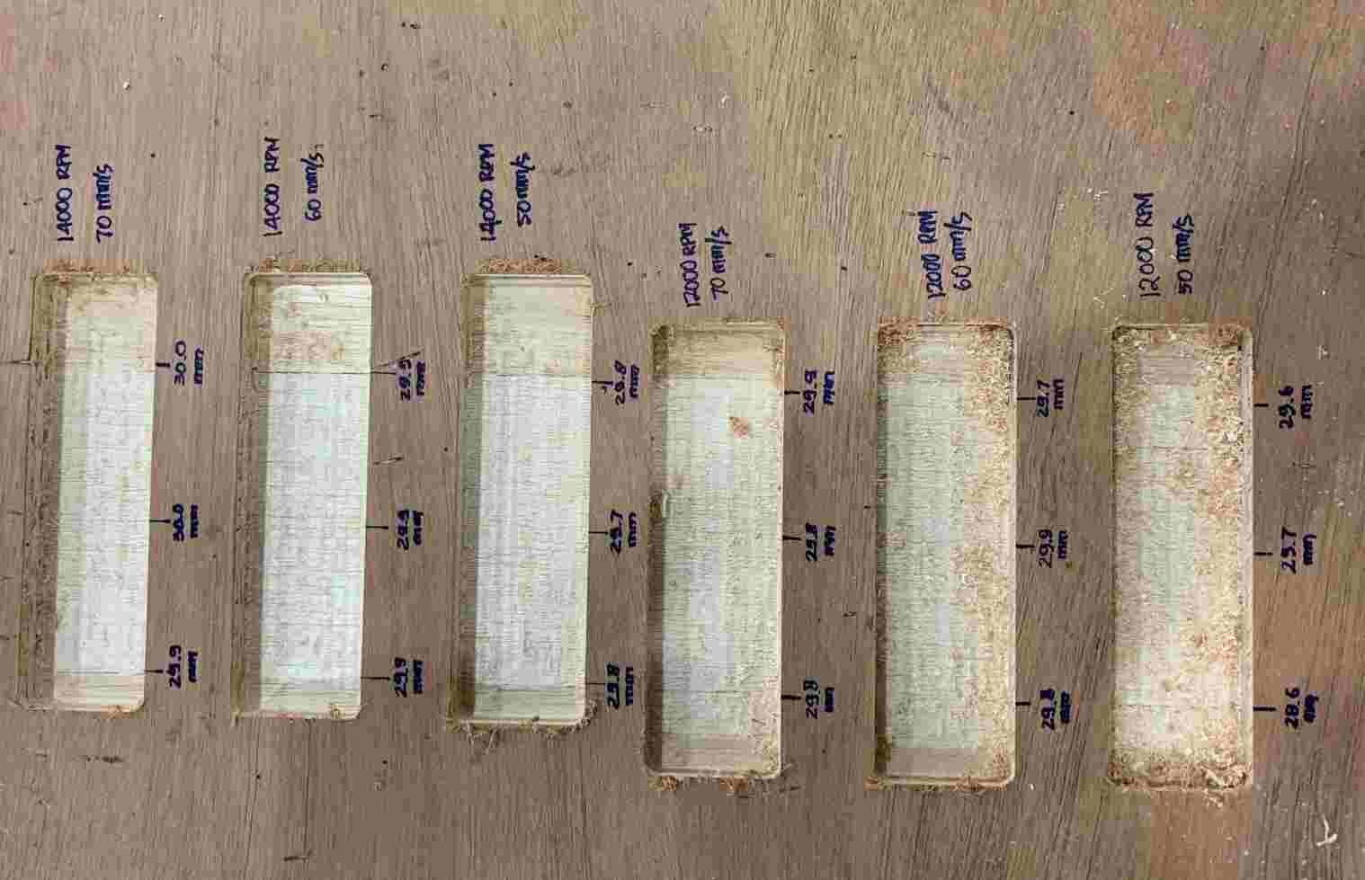
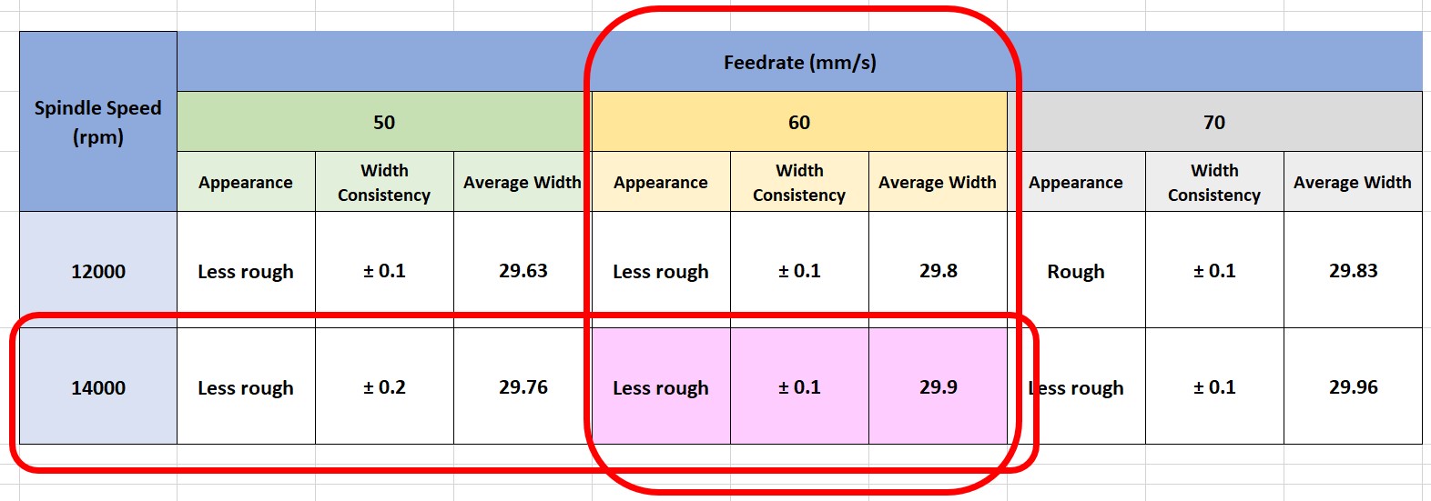
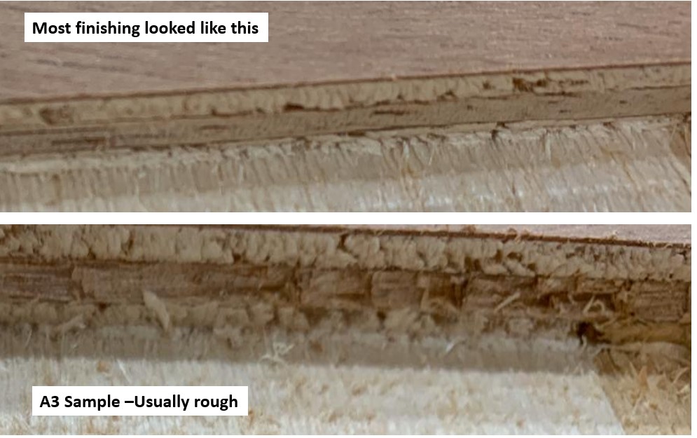
About the surface finishing, the team finds it difficult to rank the finishing for the 6 samples. The sample A3 however, is usually rough.
From this study, the team decided to select a feedrate of 60 mm/s and a spindle speed of 14000 rpm as the optimum setting for our fruther testing and personal assignments.
(2) Kerf and dogbone
Although the ESAB Knowledge Centre defines kerf for CNC shape cutting as the width of material that the process removes as the cutting tool cuts through the plate. The team agreed to use the same definiton as in laser cutting where kerf as the differences between the drawings and the actual produced parts. To determine this, a board with holes of different widths were cut.

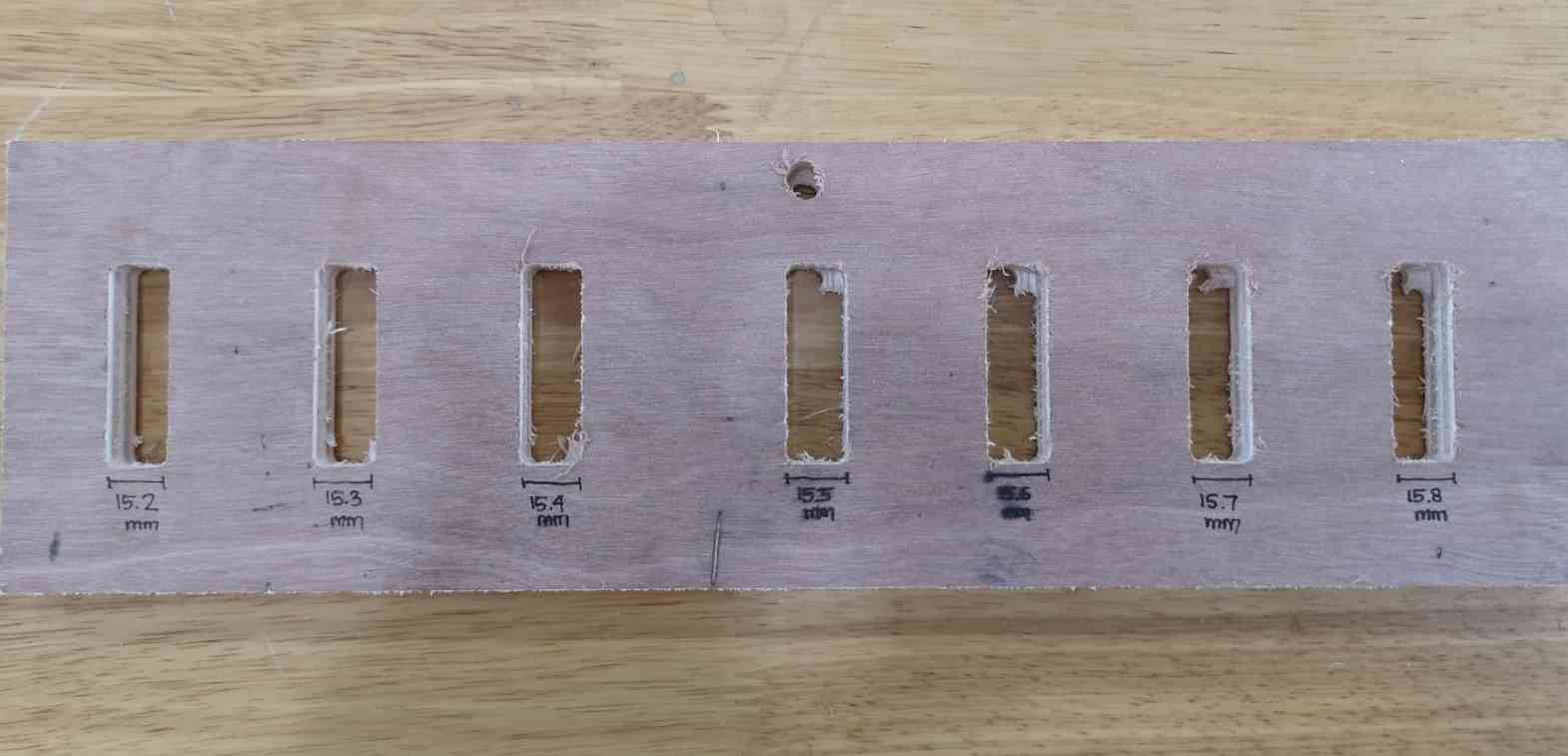
An insert pin was cut from the same stock to determine the kerf. The stock is 15.0 mm thick.

It was found that the pin best fit the 15.2mm slot, meaning the kerf is 0.1mm
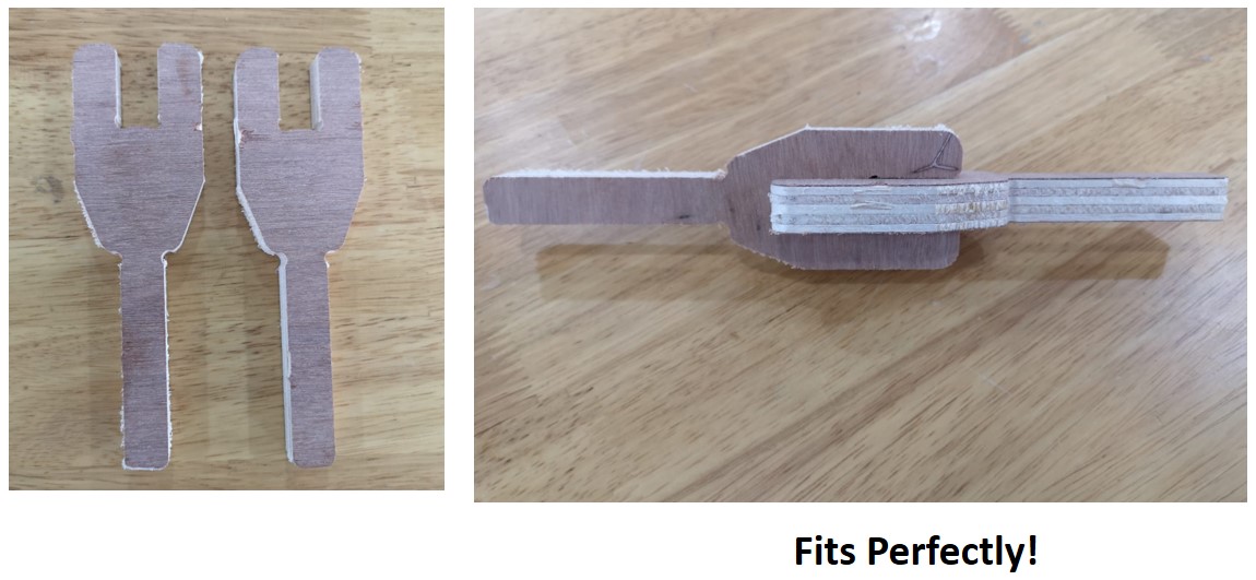
To verify this finding, the team milled 2 interlocking forks. The slots are drawn 15.2mm wide and the two fits perfectly!