Assignment 3
Week 5 is on 3D Printing and Scanning. There are 3 assignments; namely:
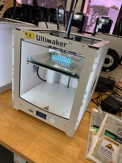
This website contains the documentation and write-up for the Group Assignment to characterize our Ultimaker 2+ 3D printer.
Characterization Process
Step 1: Downloading and Preparing the Test files
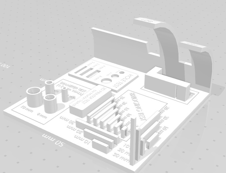
The team decided to use separate files for individual test parameters instead for using the all-in-one model such as the one shown below as this would give each member greater ownership and opportunity to participate.
The test files were downloaded from the FabAcademy.org. A total of 8 files in STL formats were downloaded. They are listed as follows:
- Clearance.stl
- Unsupported Angle.stl
- Bridging.stl
- Wall thickness.stl
- Dimensions.stl
- Anisotropy.stl
- Surface finish
- Infill.stl
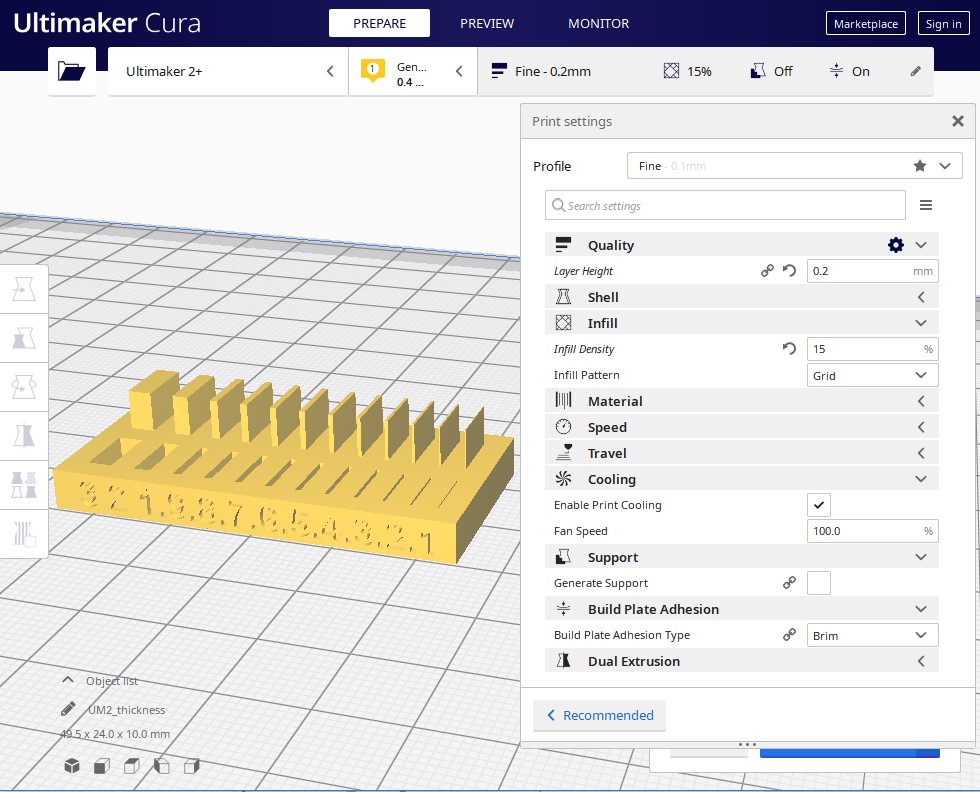
After downloading the slicer software Cura 4.5 was then used to create the gcode files that are readable by the 3D printer. At this point, the print quality must first be set before generating the gcode files. For all the test models, a quality of 0.2mm (layer height) was first used to print. For some selected models, reprints were carried out using 0.1mm.
Step 2: Preparing the 3D printer
Before printing these files, the print bed must first be leveled or calibrated. This is done by adjusting the gap between the printer head and the print bed. A piece of paper is used to adjust the printer head gap. Th gap must be such that slight resistance is felt when moving the paper
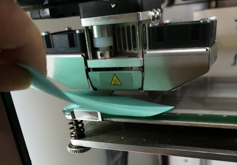
If the calibration is not done correctly, the impact on the print job can be disastrous!
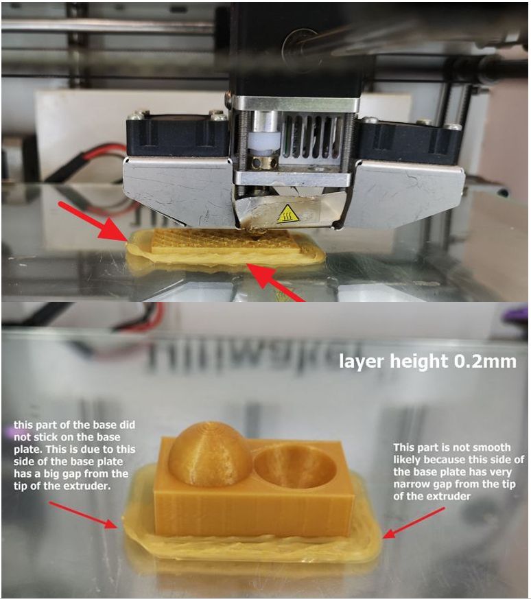
If one side of the base plate is too far from the tip and the other side is too near from the tip, the initial layer height will warp/bend like shown below.
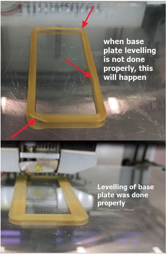
If all side of the base plate is too far from the tip, hence starting from the initial layer, warp/bend can be seen on all of them as shown in the picture below. But if the base plate levelling is done properly, the result will be fantastic.
Step 3: Analyzing the printed test specimens
(A) Thickness & Gap
This test is to determine the minimum thickness as well as the gap that the 3D printer is capable of producing. The STL file is processed using Cura 4.5. Layer height of 0.1mm and 0.2mm were tried.
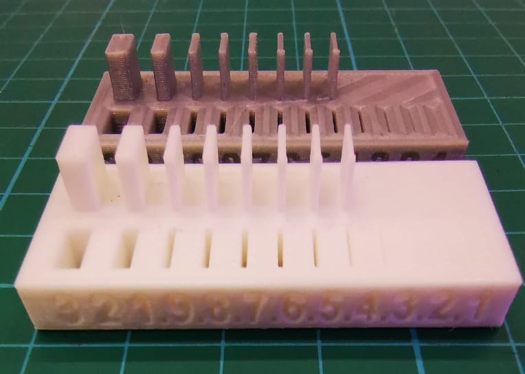
From the printed model, the minimum thickness of the fins is 0.5mm and the minimum slot hole 0.1mm. While printing time is almost doubled when the layer height is reduced from 0.2mm to 0.1mm, there is no apparent difference in the thickness and gap between both prints.
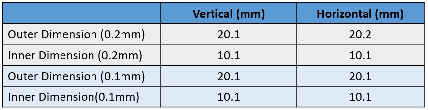
(B) Dimensions (Print Accuracy)
The objective of this test is to determine the print accuracy of the printer. A hollow cube with outer dimensions of 20mm and inner dimensions of 10mm.
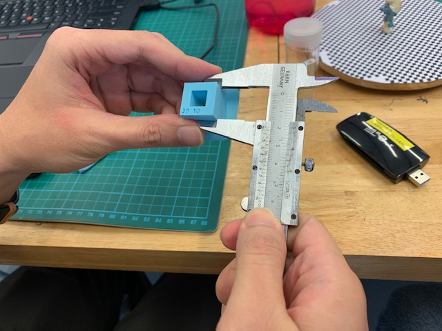
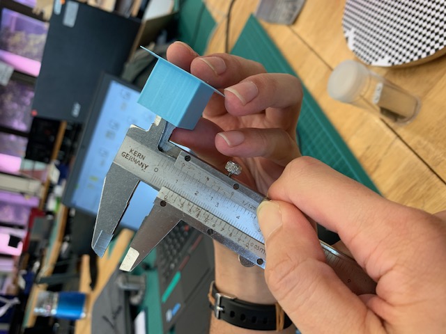
The print accuracy is generally very consistent for both horizontal and vertical direction. There is also no different when layer height of 0.1mm and 0.2mm were used.
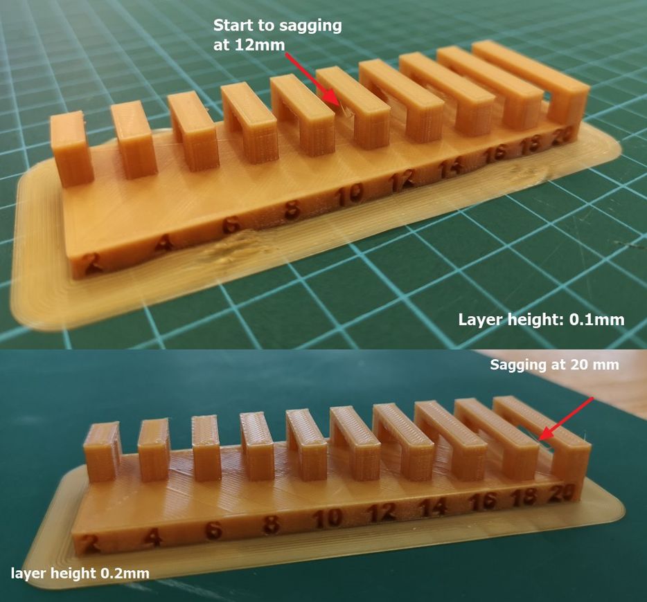
(C) Bridging
Bridging test is to evaluate the ability of the 3D printer to print a FLAT, HORIZONTAL part of the model MID AIR without the use of any support. In this testing, layer height of 0.1 mm and layer height of 0.2 mm were compared. It can be seen for the 0.1 mm, sagging is observed starting from the 12 mm gap, while for the 0.2 mm sagging is observed on the 20 mm. This indicate that the smaller the layer height, the easier the bridge to sag.
(D) Overhang Angle
Overhang is any part of a print that extends outward, beyond the previous layer, without any direct support. Knowing the overhang angle can help the designer decides when supports are required and when they can be avoided.
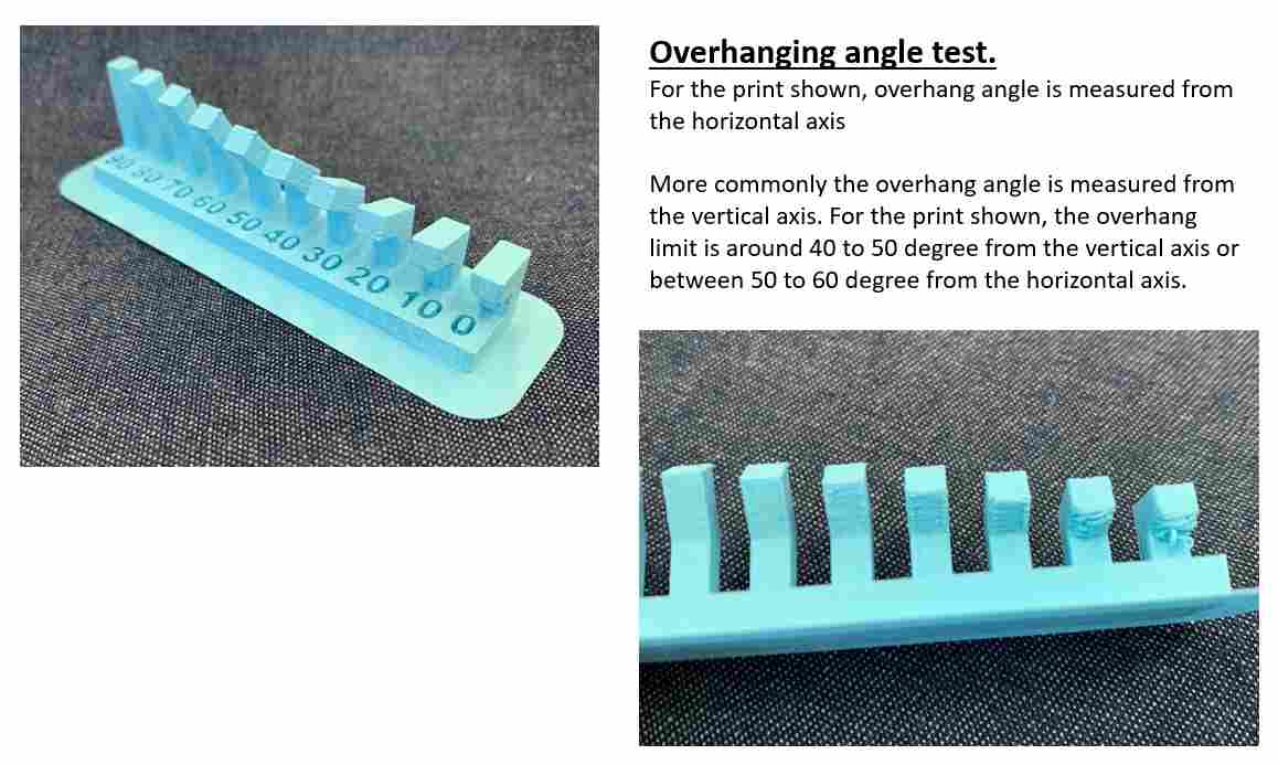
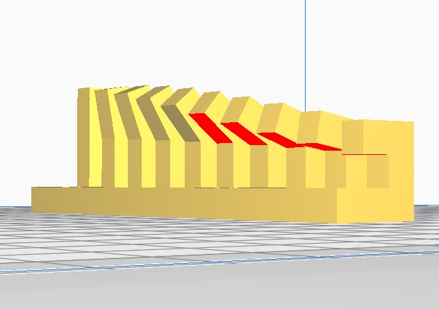
The overhang angle can also be determined without carrying out the test, the Cura software is able to accurately determine the angle at which defect would start to appear.
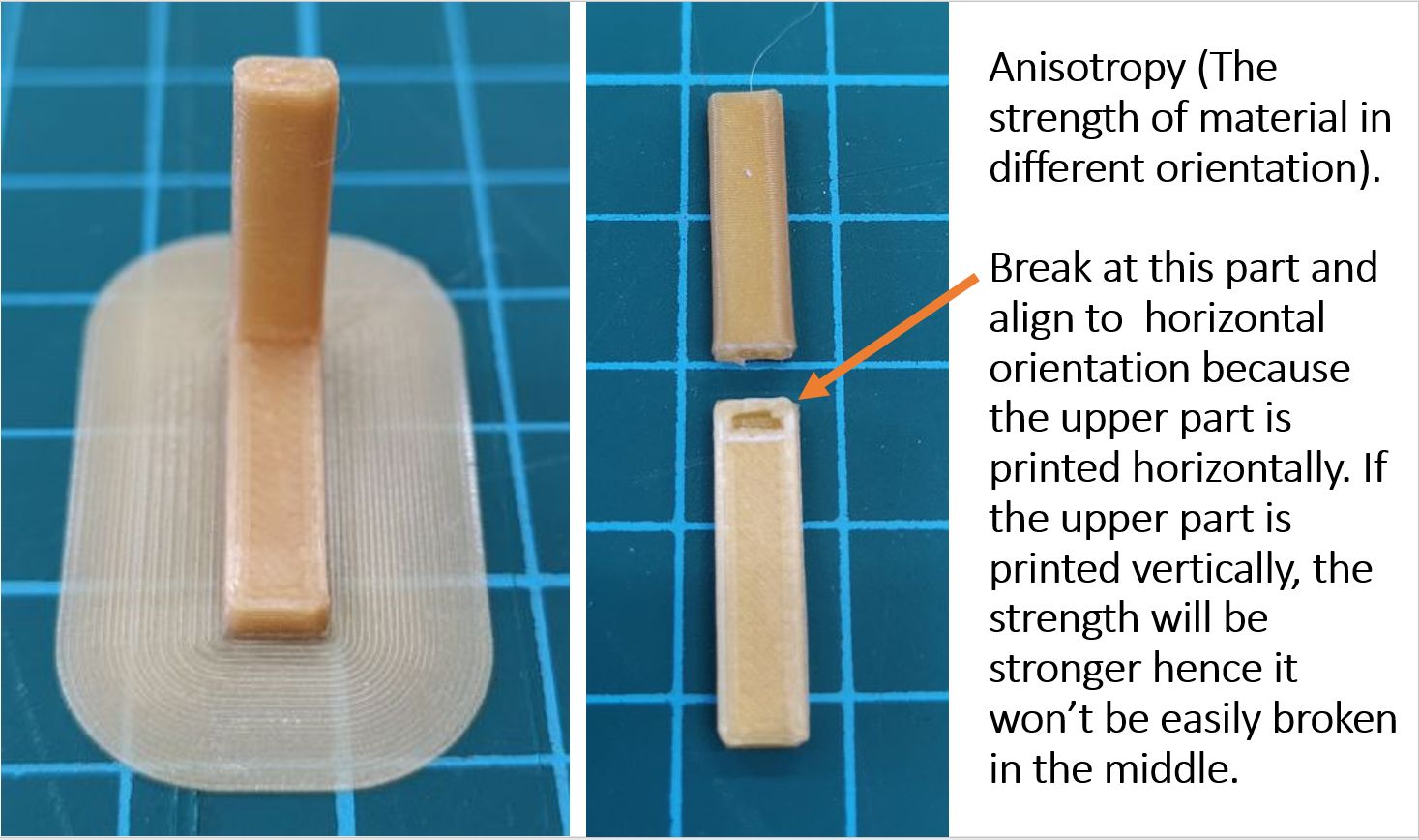
(E) Anisotropy
The importance of print orientation to the final quality and functionality of a 3D printed part is often overlook. Some 3D printed parts have inherently anisotropic properties, meaning they are much stronger in certain direction. In this test print, the upper part has a horizontal printing orientation, while the bottom part (base) has a zig-zag printing orientation.
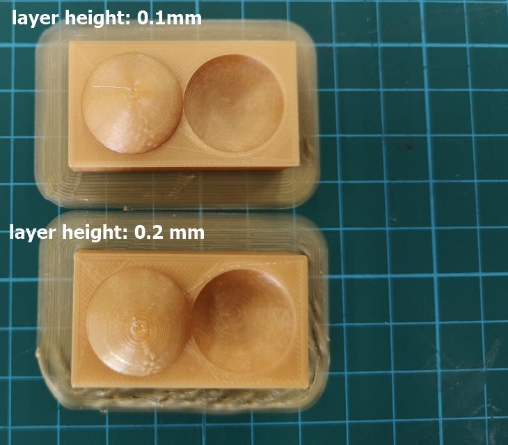
(F) Finishing
Surface finishing of 3D printed part is very important. In this testing, the effect of layer height on the surface finishing is evaluated. Layer height of 0.2 mm and layer height of 0.1 mm were compared. As can be seen below, the surface finishing is quite similar, hence between 0.2 mm and 0.1 mm layer height, the surface finishing is quite similar..
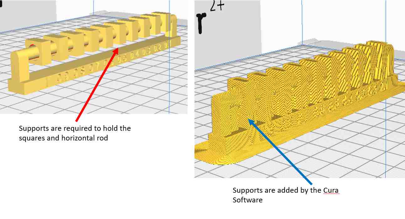
(G) Clearance
Clearance is of great importance when parts have to fit or slide together after printing. To evaluate this, the clearance.stl was first downloaded and used. This model, however, needs several supports for the holed square blocks as well as horizontal bar. These supports are difficult to clear and would hence interfere with the accuracy of clearance test.
An alternative design for the clearance test is a need. The Tolerance Test file V3.stlwas downloaded from Ultimaker 2+ reference site and used.
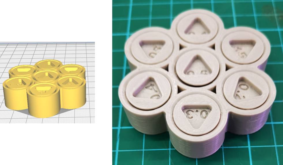
Using a layer thickness of 0.2mm, the minimum clearance using this design is 0.2mm. A value of 0.3mm was obtained when the first design was used indicating that design can affect the determination of the clearance.
(H) Infill Density
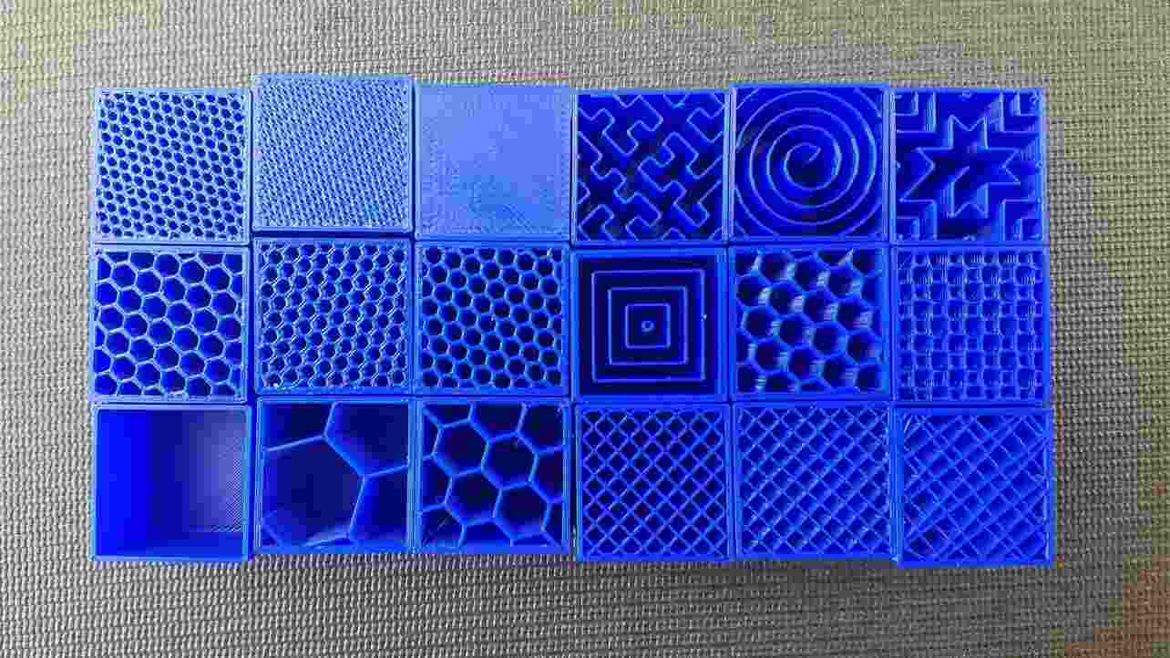
Strictly speaking, Infill density is NOT a machine characteristic but rather a setting on the machine. Infill density is the amount of filament printed inside the object and this directly related to the strength, weight of the print as well as the duration of the printing process. Different 3D print infill types, or infill patterns, can affect the object's final strength without changing the print's weight or filament used.
In this test, the rigidity (compressive load bearing ability) is evaluated using the infill.stl file from FabAcademy.org website.
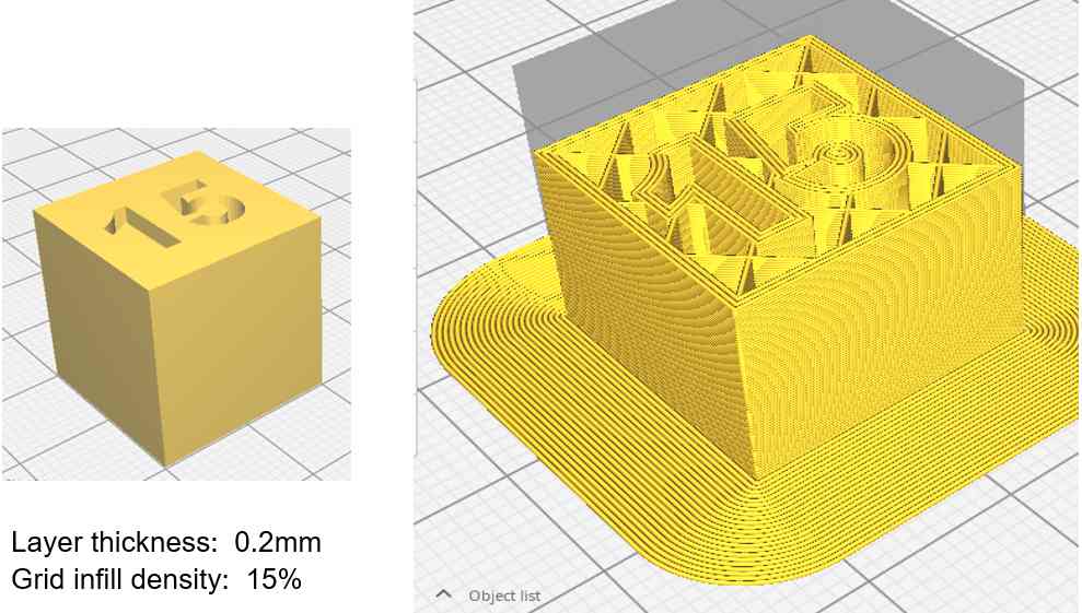
Compressive load was applied on this 20mm cube with an infill density of 15%. It was found that even with 24 kg load, there is no deformation, crack or other sign of failure.
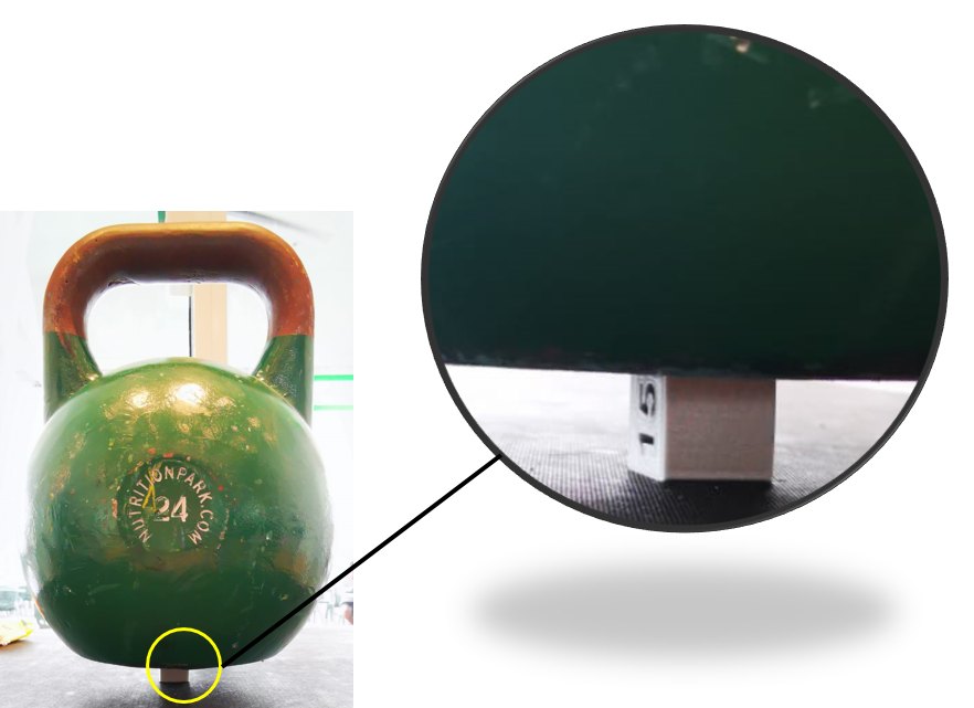
Another test was performed on the same 3D print but with only 7.5% infill density. Despite reducing the infill density by 50%, there is no problem when the 24kg weight is applied. Hence to reduce printing time the infill density can be reduced. Besides changing the infill density, the infill design is also known to affect the load bearing ability. Due to time constraint, the team did not managed to test other infill designs. Some interesting infill designs are available from All3DP.com website