Assignment 4
Week 6 is on Electronics Design. There are 2 assignments; namely:
This website contains the documentation and write-up for the Group Assignment
(A) Using the Multimeter
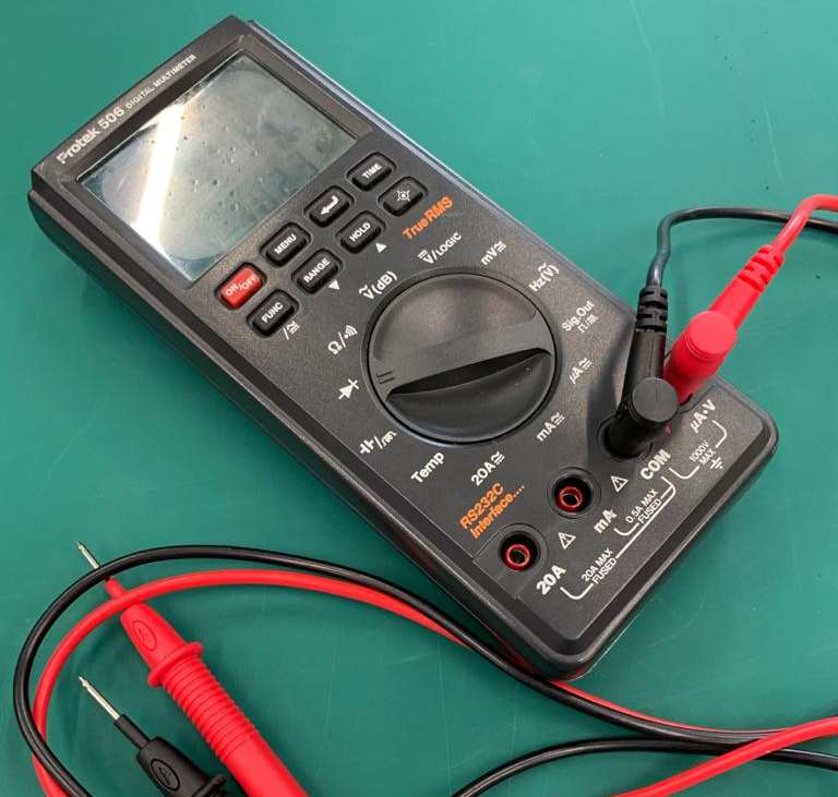
This handy piece of equipment is used for measuring voltage, current, resistance and continuity.
- To measure Voltage
- Plug the black probe into COM and the red probe into μA.V.
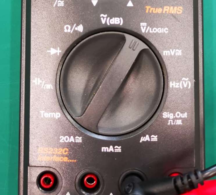
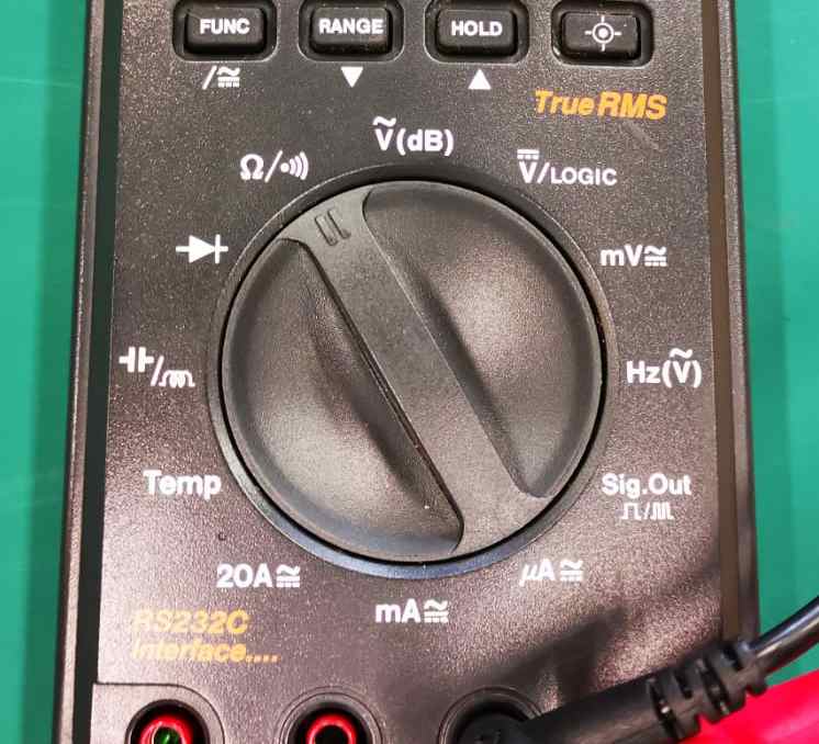
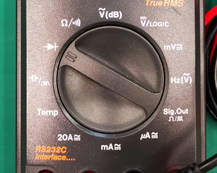
- Set the multimeter to "V/LOGIC".
- Connect the black probe to the negative terminal or '-' and the red probe to the positive terminal or '+'.
Measuring voltage
- To measure Resistance
- The black and red probes are plugged into COM and μA.V as in for voltage measurement.
- Set the multimeter to Ω.
- Connect the 2 probes to the two ends of the resistor (polarity is not important here) and apply slight pressure. The resistance will be displayed
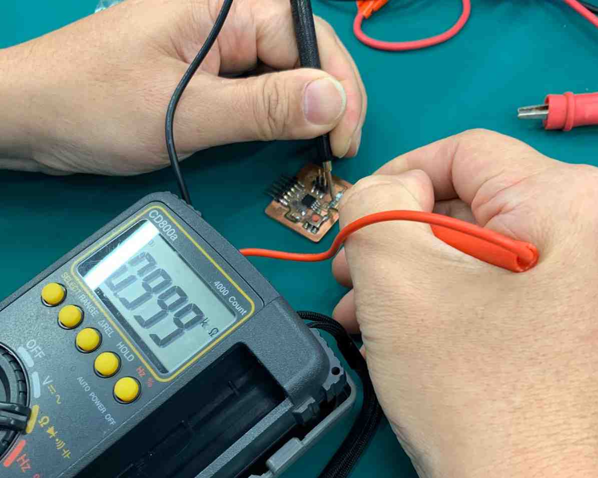
Measuring a 1kΩ resistor
- To measure Current
- Remove the solder from the jumper
- Solder jumper wires to each end of the jumper
- Plug a red crocodile clip to mA
- Plug a black crocodile clip to COM
- Set the dial of the multimeter to the milliampere current setting.
Note: Overloading the current can result in a blown fuse rather than just an overload display - Connect the crocodile clips to the jumper wires
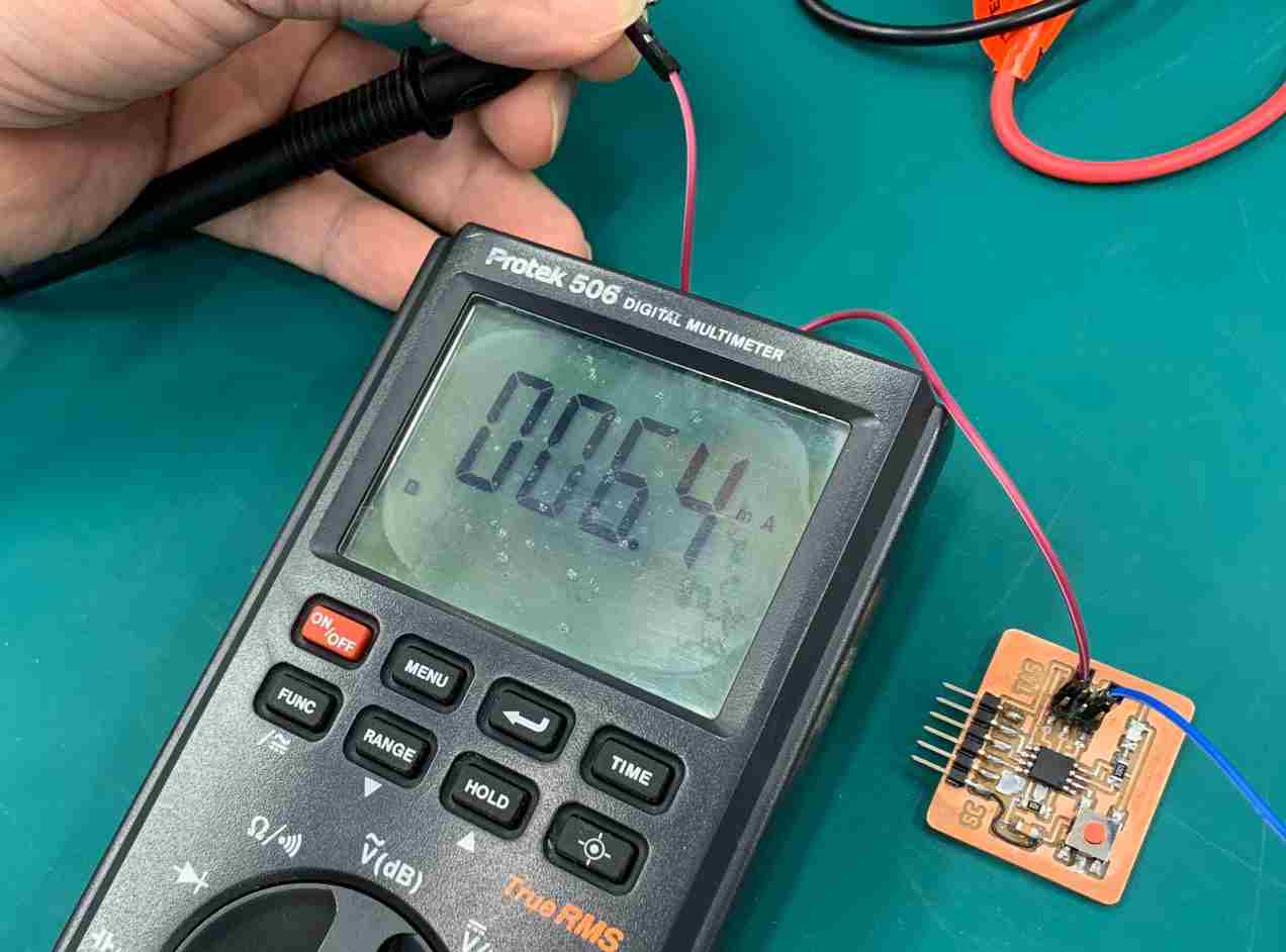
- The current will be displayed
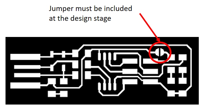
- After measurement, the jumper wire must be removed and the jumper re-soldered closed
Current measurement for electronic circuit board is not common, even so for surface mount circuit boards. To measure current, the flow of current must be physically interrupted and the multimeter must be connected in-line. Hence to physically interrupt the circuit, trace must be broken so that jumper wires can be connected! Current measurement for SMD must hence be forward-planned (refer to image)
- To check Continuity
- Set the multimeter to 'Continuity' mode. This is usually displayed as a diode symbol with propagation waves around it.
- The black and red probes are plugged into COM and μA.V as in for voltage measurement.
- Slightly press the 2 probes on the two points to be checked. Listen for any tone emitted
Continuity testing is actually testing the resistance between two points. If the resistance is low (less than a few Ωs), then the two points are connected electrically (a tone is emitted). If resistance is high, the circuit is open, and no tone is emitted.
This test helps ensure that connections are made correctly between two points. It also helps to detect if two points are shorted.
(A) Using the Oscilloscope
The oscilloscope is an instrument for graphing an electrical signal as it varies over time. Most scopes produce a two-dimensional graph with time on the x-axis and voltage on the y-axis. Although the panel is intimidating-looking, the operation is actually quite simple once the user is familiar with the knobs and buttons. The user notes on Sparkfun.com is especially useful in getting a head start with the oscilloscope.
Click Here for Sparkfun Tutorial on using an Oscilloscope
For this assignment, the oscilloscope is used to observe the signal from a Hello Board. A ATtiny45 Hello_World board was provided by our coach. This is the same board that we have to build for our individual assignment.
The program loaded in this board is a blinking program that allows the button as well as the LED to be tested. When powered, the LED will light up indefinitely when the button is pressed once. On pressing the button a second time, the LED will blink slowly, at an interval of 500 milliseconds. When pressed a third time, the LED will brink rapidly at an interval of 150 milliseconds.
To observe the operation, the board must first be powered before the signal output can be tapped to the oscilloscope. There are several ways to do this and the easiest is simply to draw current from the ISP programmer that is plugged into the computer USB port. The other way is to use connecting wires as shown in the image below:
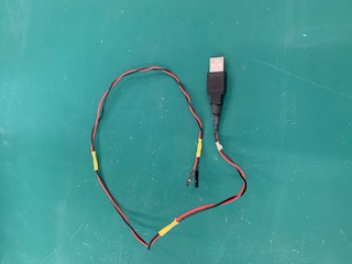
The more correct way is to use a DC power supply, where voltage and current can be adjusted
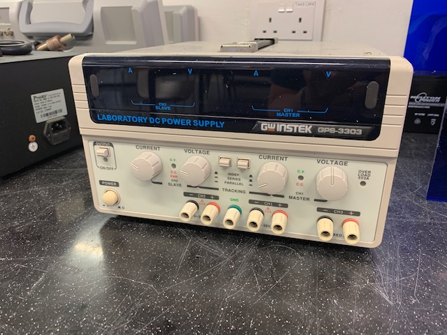
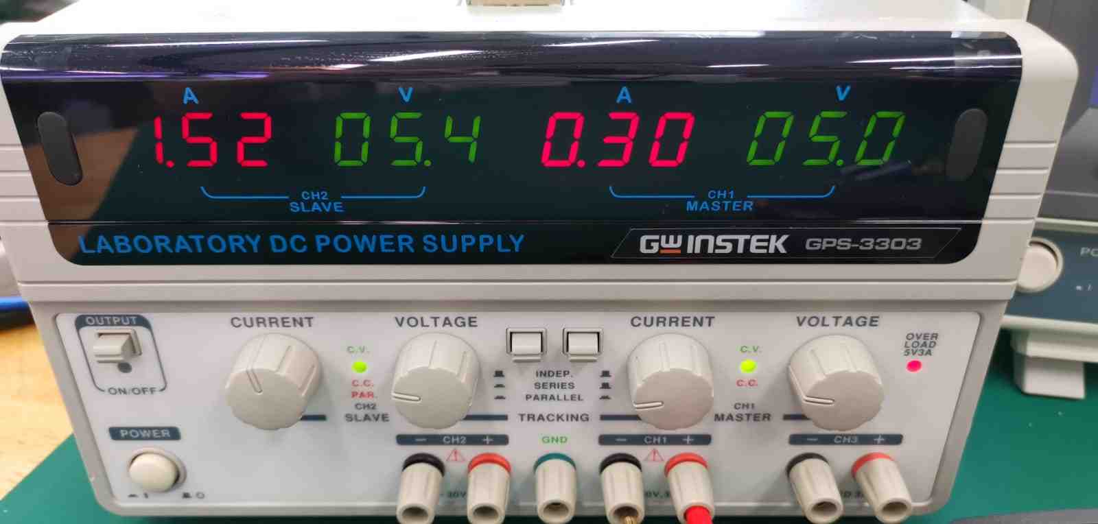
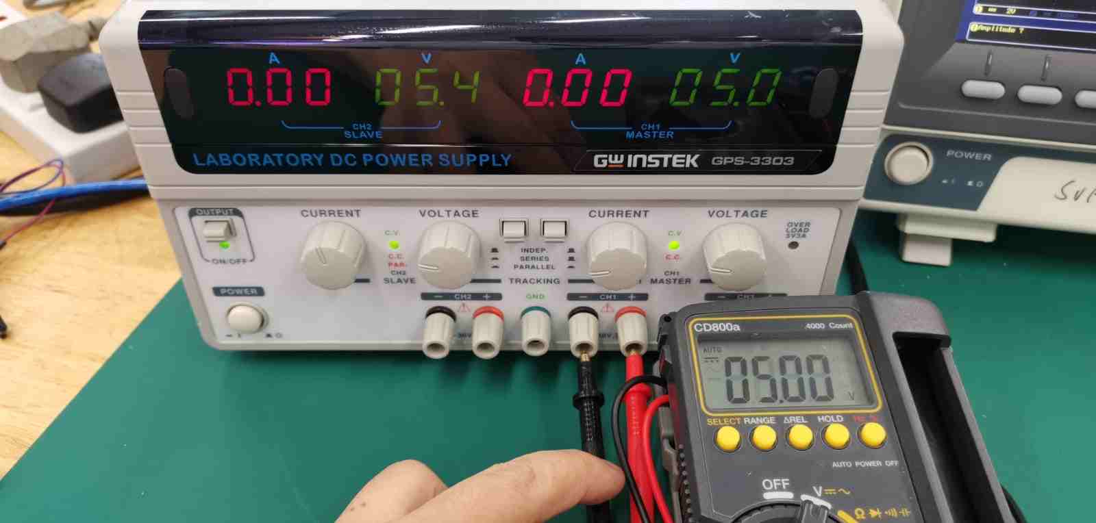
Setting the current to 300mA and voltage to 5.0V
After powering up the Hello_board, the signal can be tapped from the LED by connecting the oscilloscope probe to the anode of the LED and GND trace.
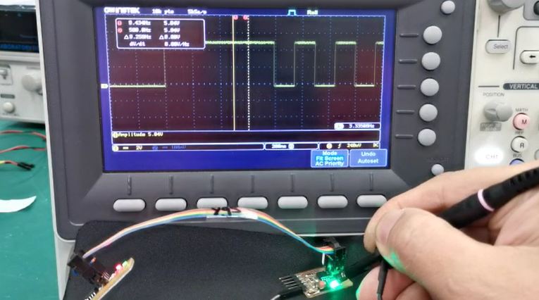
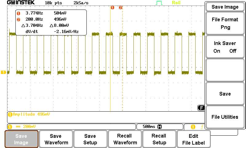
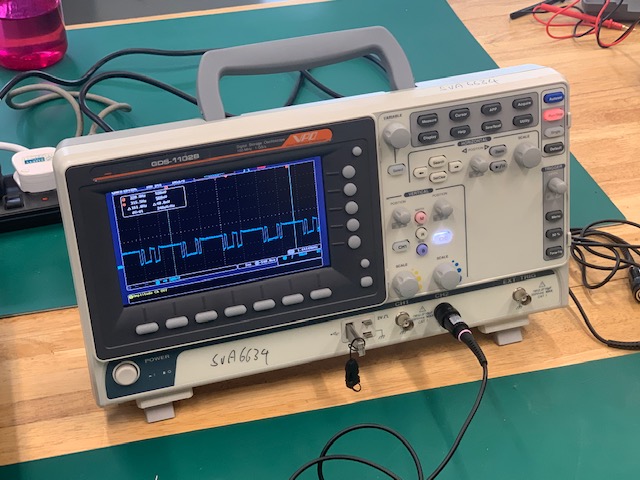
When the connections are done correctly, the signal can be observed on the oscilloscope. Below are images of what the team observed when the button is pressed Once,Twice and Thrice
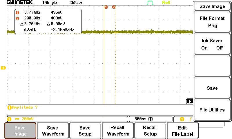
Pressed ONCE, the LED is on continuously and a stable horizontal voltage is observed
Pressed TWICE, the LED blinks slowly
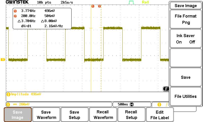
Pressed THRICE, the LED blinks rapidly