16. Molding and Casting
For this week I designed a mold of the map of Rwanda, milled it, and finally cast it.
Design
-
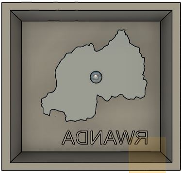
The design as (shown in the picture below) was designed by first, creating a rectangular container then drafting the walls. I got the image of the map from here then used Inkscape to vectorize it and imported it in Fusion by going to INSERT> Insert SVG then aligned it with the bottom face of the container and then extruded it, I also created a semi-sphere which I put at the center in order to highlight the location of the capital city. Finally, I included the letters “RWANDA” which were mirrored.
-
As shown below, to make the milling easier the design walls have to be drafted, to do so I selected the walls to be drafted and then went to Modify>Draft then select the draft orientation (as shown in the image below) and angle of the draft(which in my case was 12 degrees).
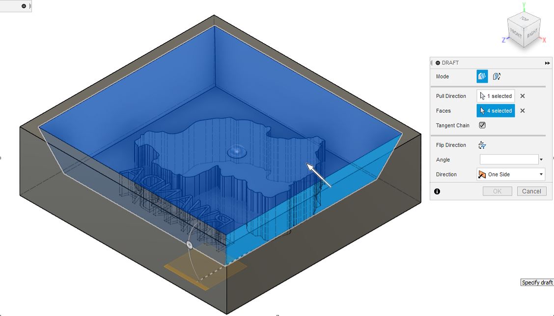
Draft process
Fusion 360 design
Milling
-
For the milling process I used MODELA Player 4 software. I first selected the material as Modelling wax from the top right corner of the main view.
-
As shown in the pictures I went to Set> Model Then information such as Dimensions appeared.
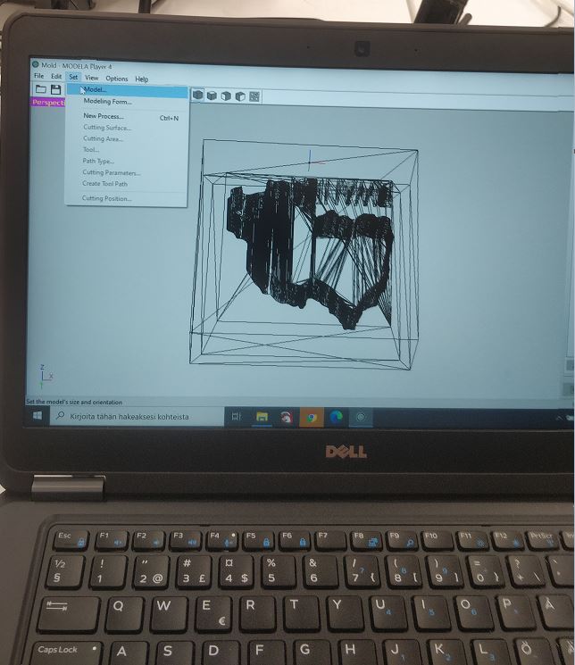
Set model
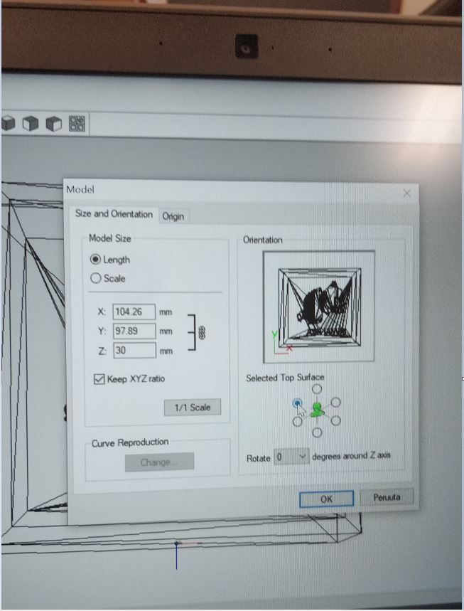
Dimensions
- Next I clicked on origin and set the origin at the front left corner of the material.
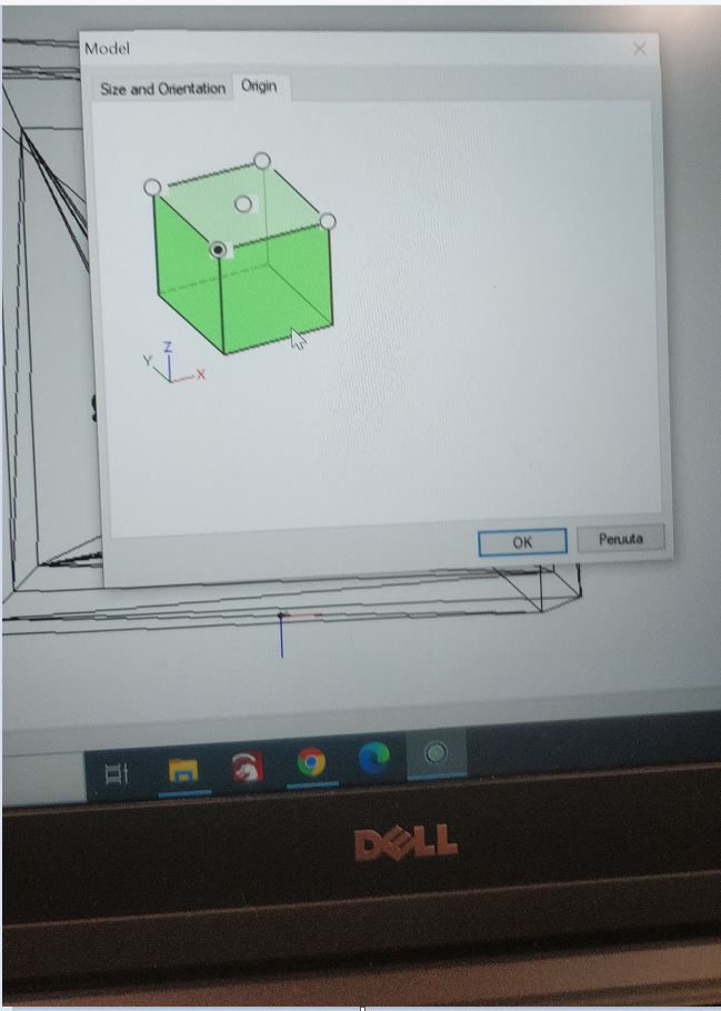
Origin
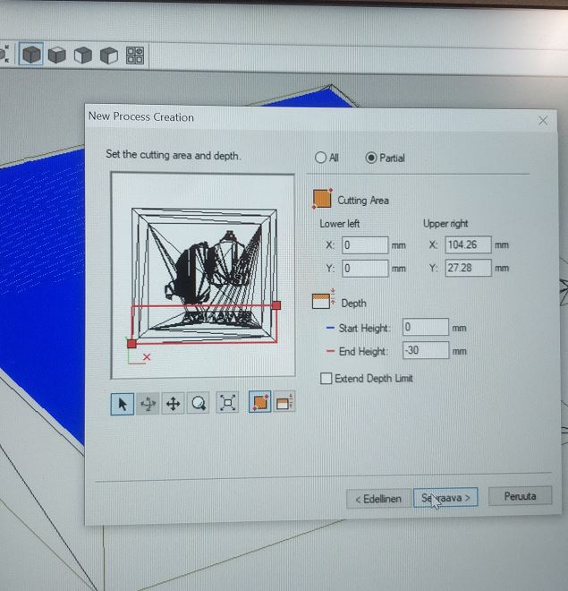
- Next by going to Set>Modelling Forms information about the depth of the design, slope, and cutting area could be seen.
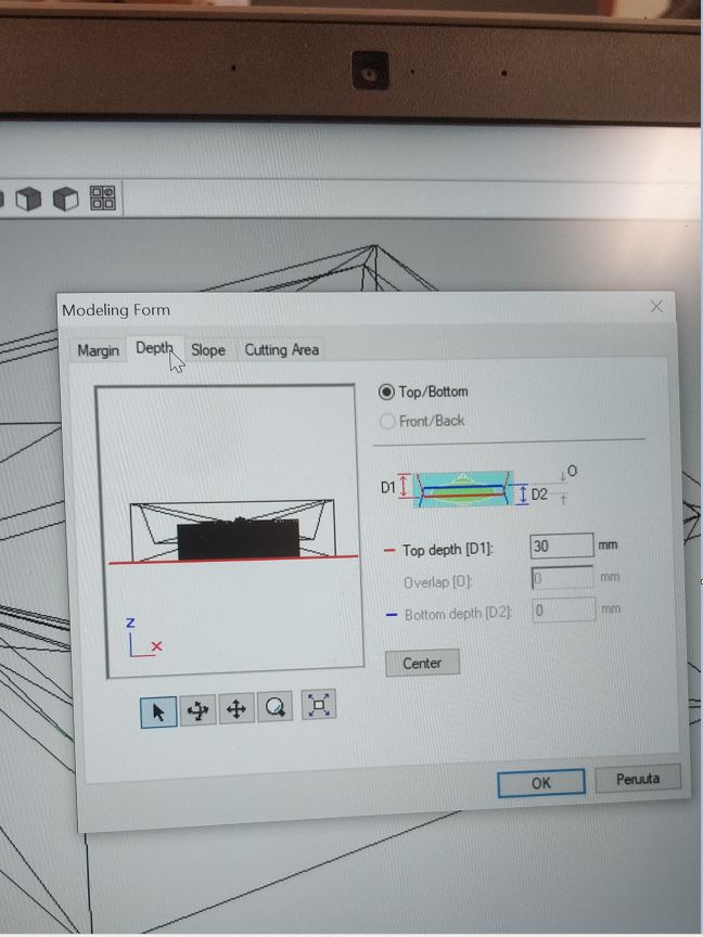
Modelling forms
-
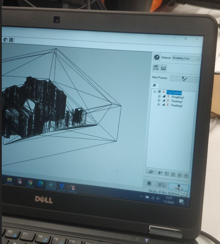
For my design, I did a common Roughing(overall milling which is not accurate to details) for the whole design and then did two Finishing tasks(Milling which is accurate to details), one for the map with a 3mm tool and the next one for the letters with a 1.6mm tool because the letters are too small and need a different tool. To do Roughing I went to New Process Creation>Roughing .
-
I selected the part on the design that has to be roughed.
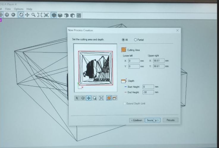
Selected part for Roughing
- Then, I reviewed the cutting parameters
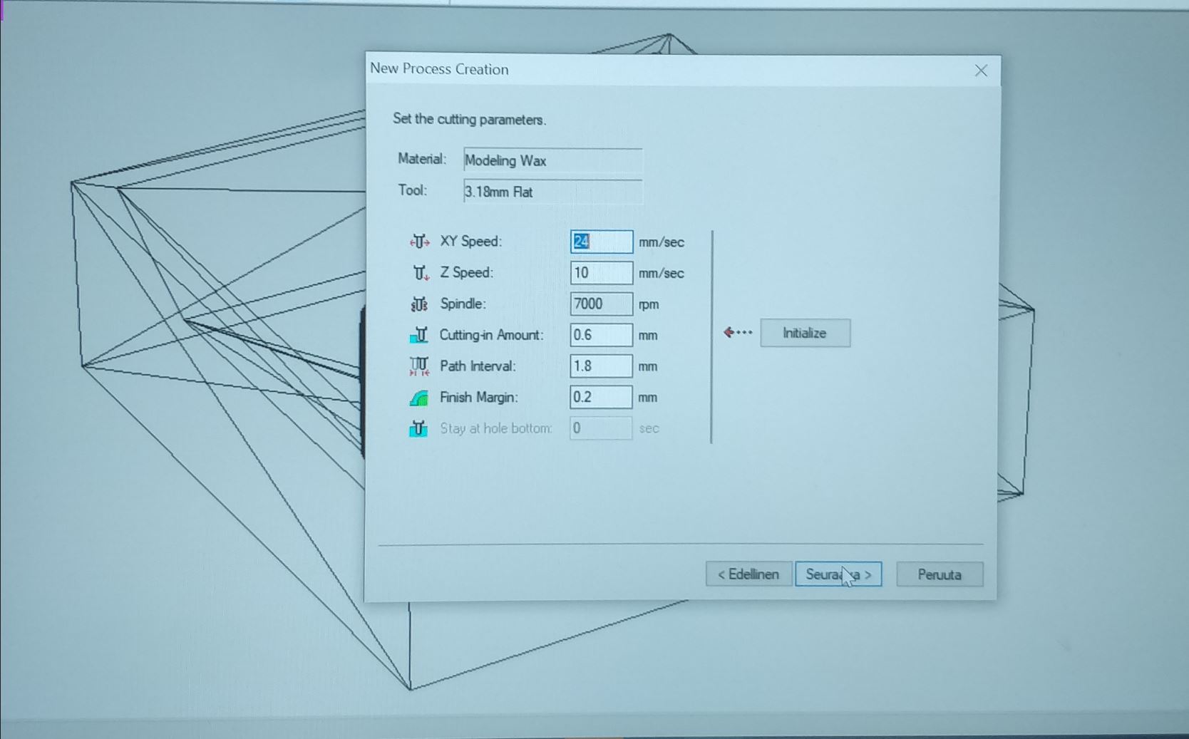
Cutting parameters
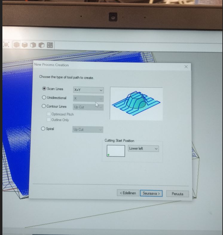
- Next, for Roughing I selected Contour lines Tool path type.
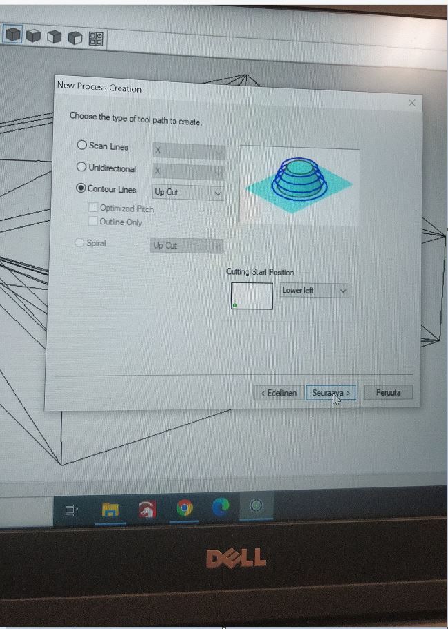
Roughing Strategy
- After selecting roughing I then simulated how it would look like after roughing(see picture below).
Simulation after Roughing
- Similarly I again chose New Process Creation>Finish1 where I selected only the map part of the design (as shown in the picture below), then I simulated how the result would be.
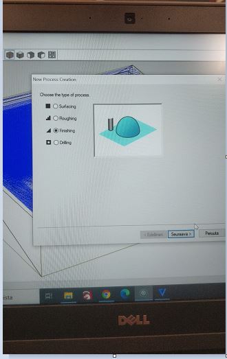
Finishing1
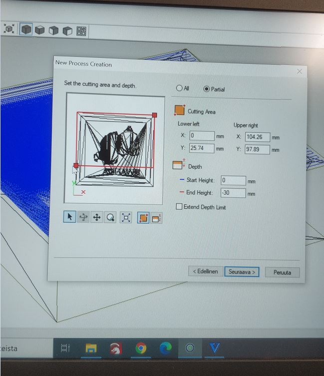
Selected part for 1st finishing
- Next, I selected Scan Lines tool path type.
Finishing1 tool path type
- For Finish2 I changed the tool to the 1.6mm tool so that the letters could be done well.
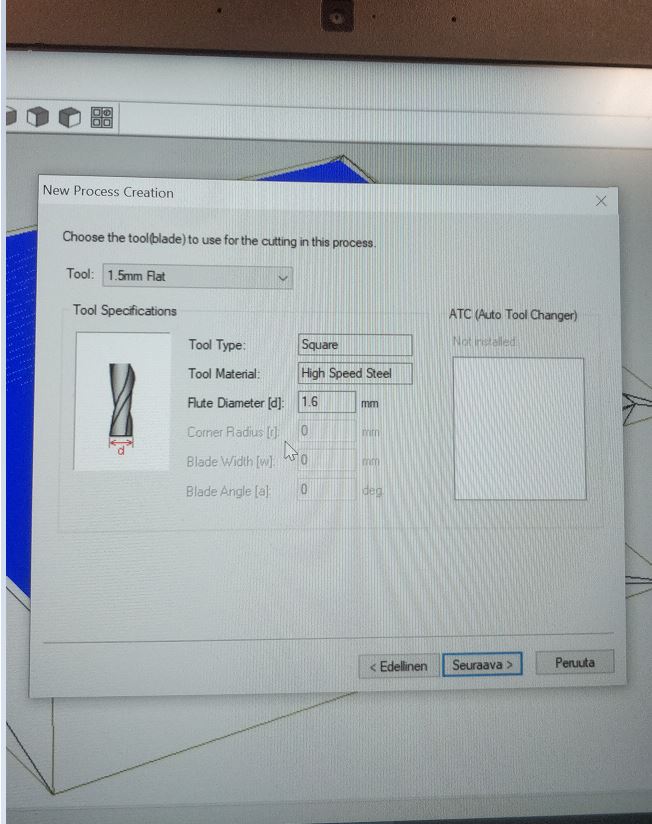
Change tool for finishing2
selected part for Finishing2
- Next, I selected Scan Lines tool path type.
Finishing2 tool path type
Finishing2 simulation
- After the whole setup was done it looked as shown in the picture below.
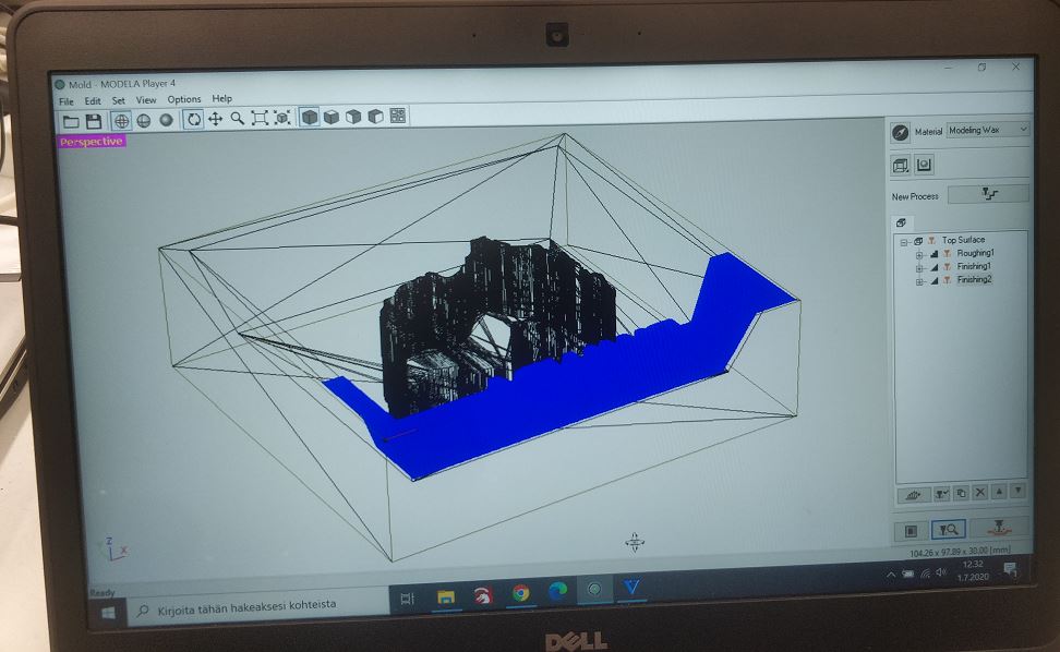 After setup
- After all these settings were done, I picked up the wax material and the milling base and taped both (as shown in the pictures). Then I used hot glue to stick them together and placed them in the milling machine. After this, I set the origin of the SRM 20 milling machine using VPanel Software to the front left corner of the material.
Taping
Glue
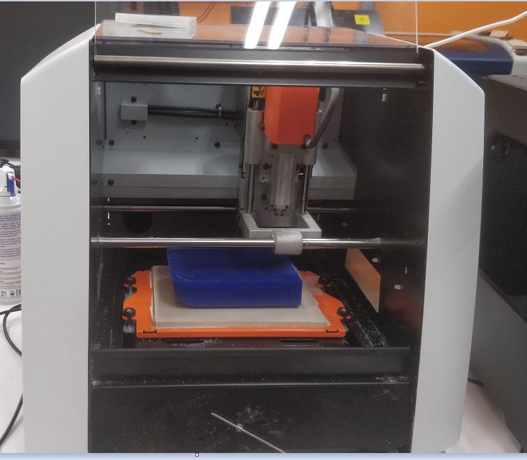
Placed in milling machine
- In The MODELA software after pressing cut The milling machine started doing the job and later on I returned to change the milling bit and pressed continue in order to do the finishing for the letters.
Cut
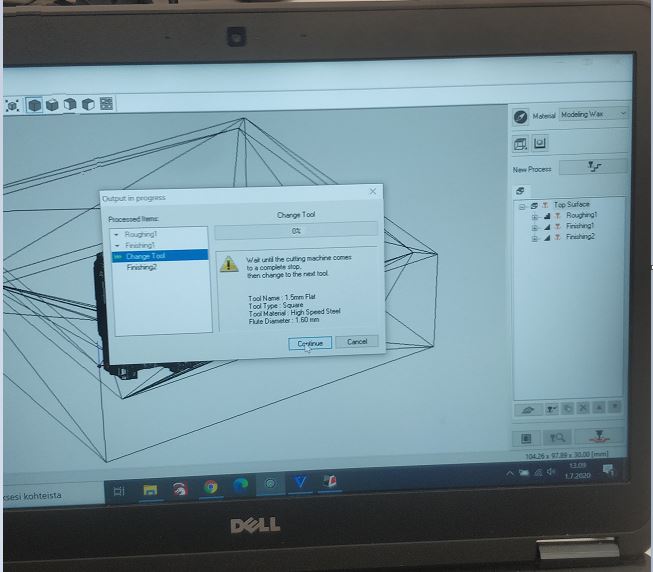
Continue and change tool
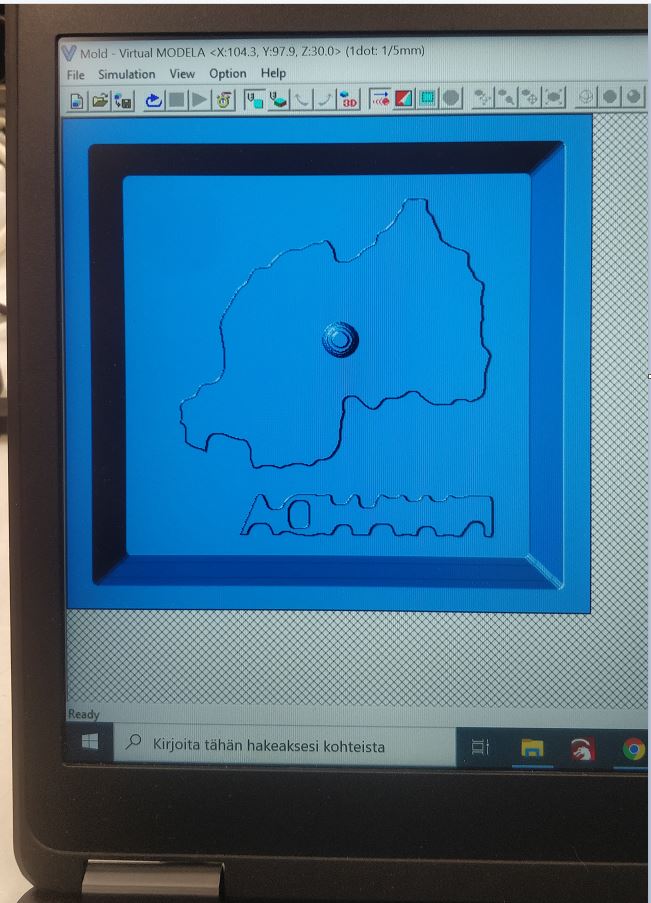
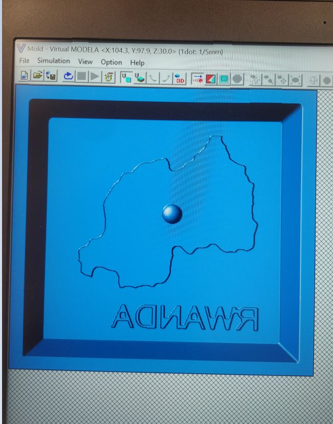
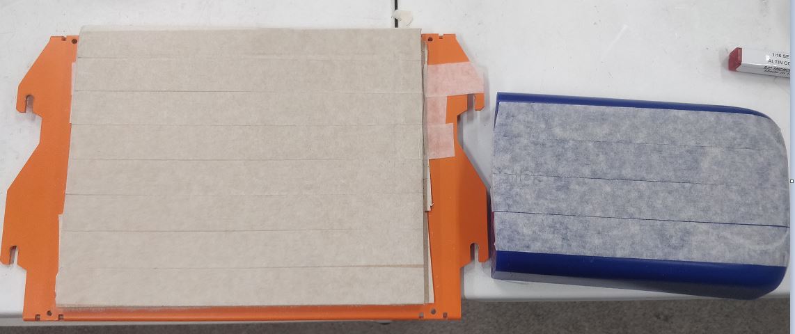
- The final mold looks as shown in the image below.
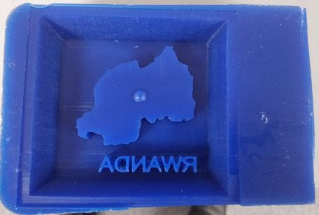
Mold
Casting
- For the casting part I used Smooth-sil 940 and later on used Smooth cast 305 in order to get the final results.
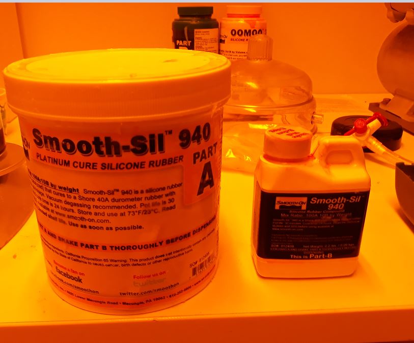
Smooth-Sil 940
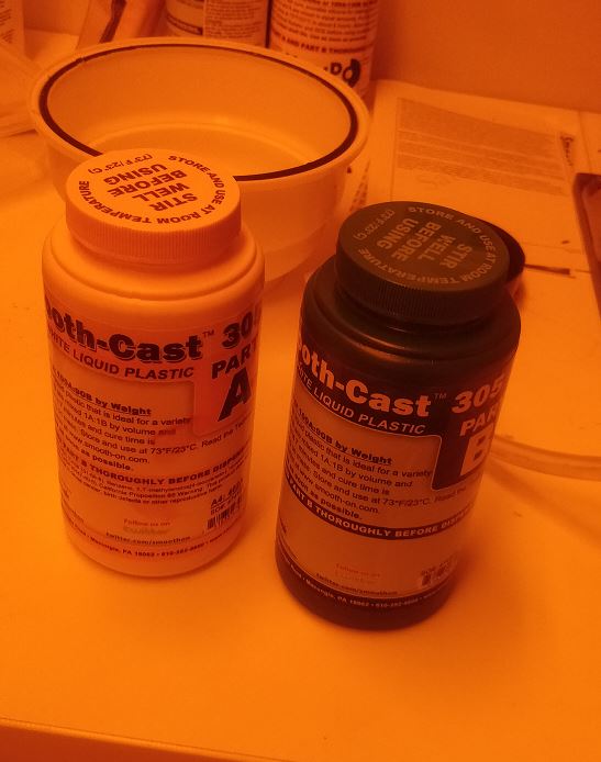
Smooth cast 305
- With Smooth-Sil 940 I mixed two products A and B at a ratio of 100:10 by using an electronic balance (as shown in the picture). Then I proceeded to do the vacuum degassing in order to remove all the air bubbles after mixing. After all this, the mixture was poured into the mold and brought to rest for 48 hours.
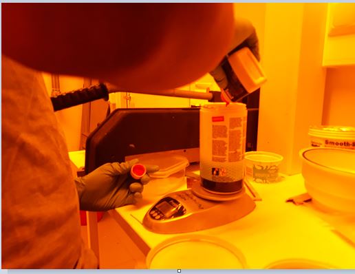
Mixing
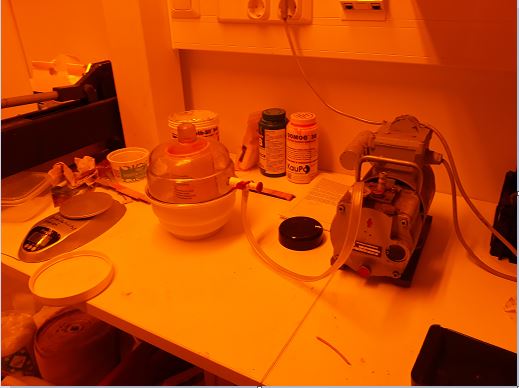
Vacuum degassing
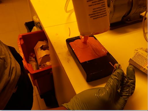
Pouring into the mold
Wait for 48h
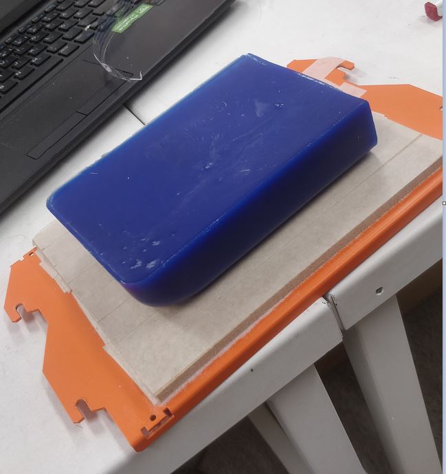
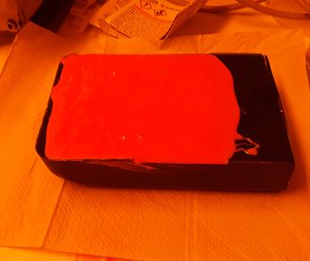
- The results after 48h of waiting are as shown below.
After casting
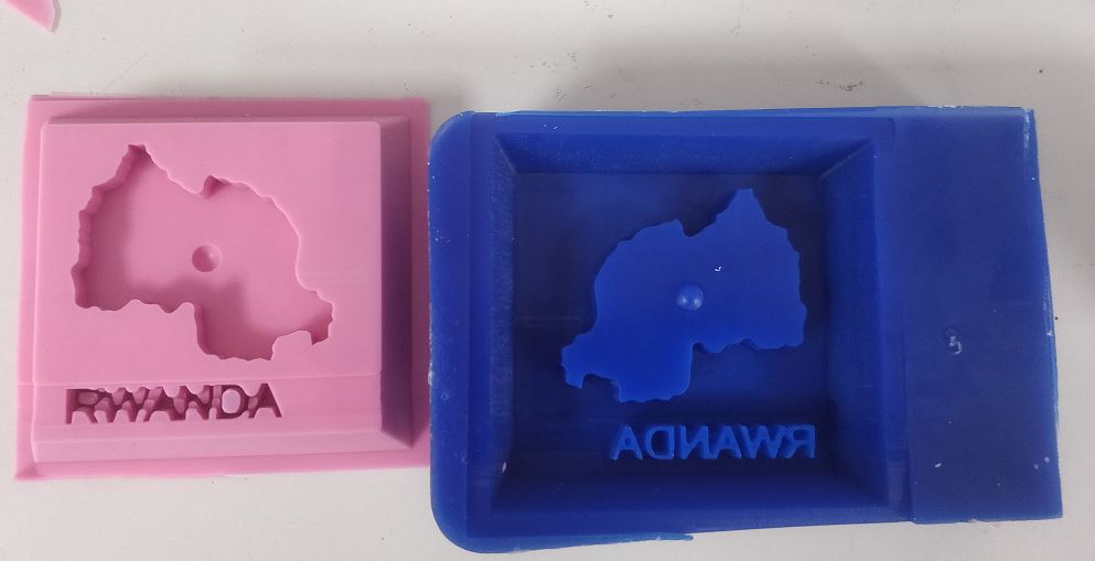
- Next I used Smooth cast 305 in the Cast obtained previously, The smooth cast was mixed at a ratio of 100:90 and brought to rest for 30 min. The results of the whole process are as shown below.
Casting again with Smooth cast 305
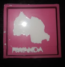
As shown below the results came out very well except the letters which were not perfect. However, with a smaller tool, the letters could have been better. Moreover, The Smooth Cast 305 couldn’t go between the letters as they’re close (should have put more space in the design).
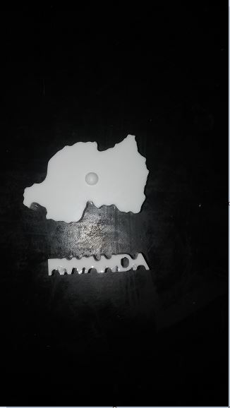
Final product
Group Assignment
In the group assignment, We used Smooth-Sil™ 940, OOMOO™ 30, and Smooth-Cast® 305 to test casting. The documentation can be found here.