Final Project
This page contains my Project development phases from the initial idea to the last Product.
Initial project idea
-
I’m thinking about desgning a portable weather station that can measure temperature, humidity and can also display date and time. Although I’m not clear about the whole structure, I think it should be enclosed in a box where there is the electronics inside and outside there’s an LED display that shows all the measurements, I’m also thinking about extra functionalities like an alarm and an extreme weather warning.
-
My project idea later changed to be a simple working environment sensor that could measure temperature and humidity of a work place. This kind of device could be installed in offices, schools and other Workplaces.
Presentation Slide

Presentation video
2D design
-
For my 2D design I engraved and cut a logo for my final project which was designed in the computer aided design week.
-
To perform laser engraving I saved the GIMP design as an image (png), then I uploaded the image in Inkscape.
-
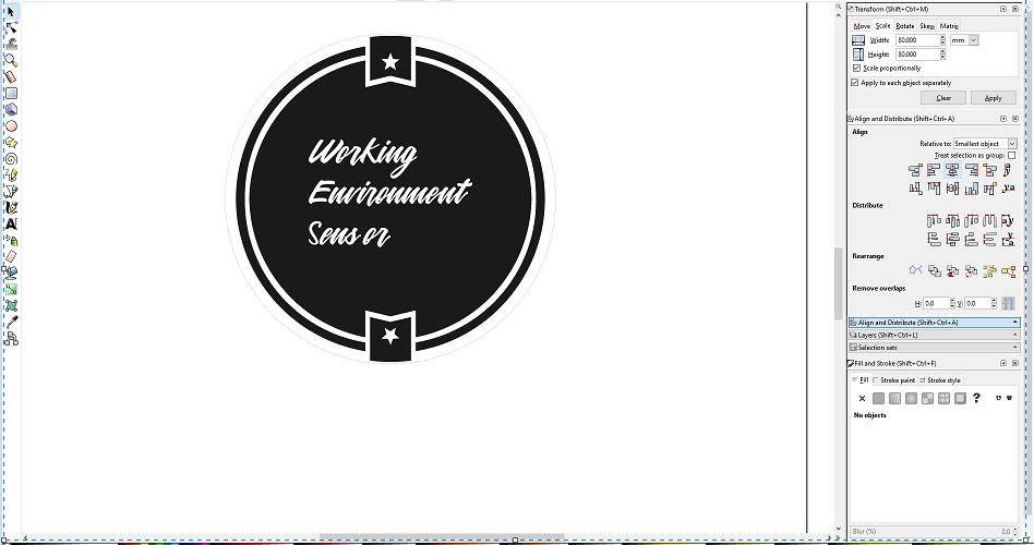
Since I needed the logo to be cut out of the material after being engraved, I drew a circle around the Logo by going to create circles after drawing the circle I aligned it with the logo by going to Align and distribute and select center with vertical axis and center with horizontal axis with respect to the logo position.
 Circle
 -
After the circle was properly aligned with the logo, I then made it’s line thickness as 0.02 mm as per the laser cutting settings. Next, I saved the inkscape design as PDF.
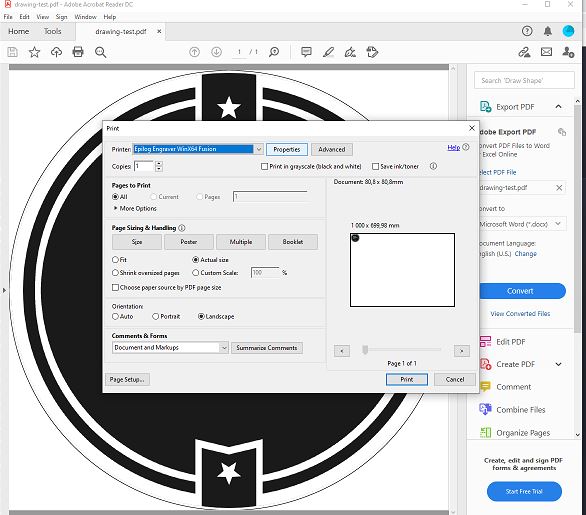 PDF
PDF -
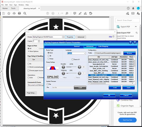
In the PDF file I went to Properties> Advanced and then selected the material as 3mm_MDF_cut_Engrave .
 Material for Engraving
 -
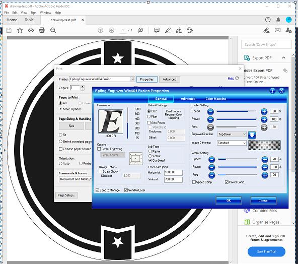
The general settings were left untouched.
 Laser settings
 -
After that I followed the steps to use the laser cutter and obtained the final product.
![]() Logo after laser engraving and cutting
Logo after laser engraving and cutting
3D design
For the 3D design I modified a little bit my design for computer aided deign to put put the door on the other end of the case.
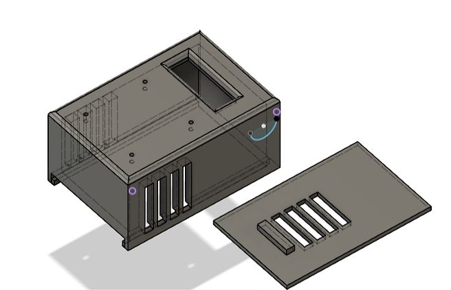 3D design
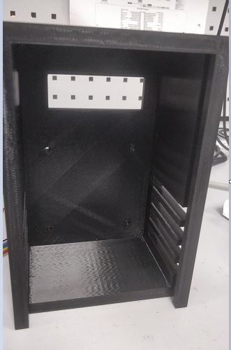 3D printed case
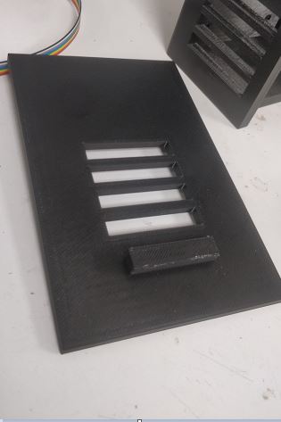 3D printed case door
Board design and Manufacturing
- I designed the board using Eagle software and finally milled it to get the final PCB. In the design I followed the same design for the programmer designed in electronics production week and added extra components like 4 pin connector for the HC06 bluetooth module, a 10 pin connector for the LCD interface and a three pin connector for the DHT11 sensor. After designing the scchematic I worked with the layout where I did routing, then I milled the board using SRM20 milling machine. Finally, I soldered all the components and all the above mentioned steps are as shown in the images below.
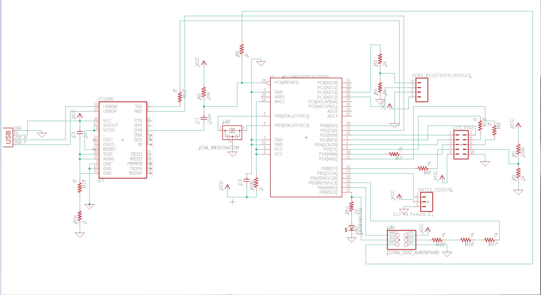 Board schematic
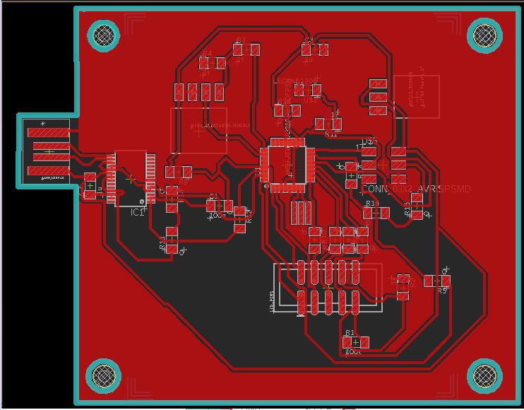 Board Layout
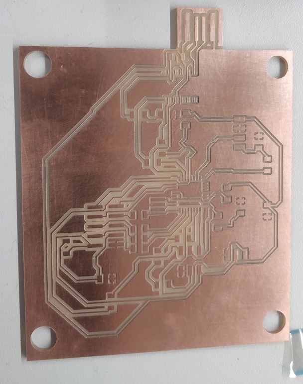 Board after milling
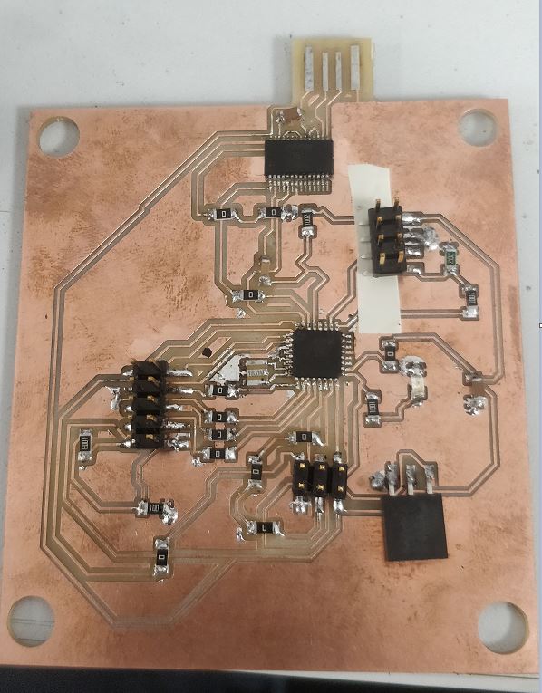 Board after soldering
Programming
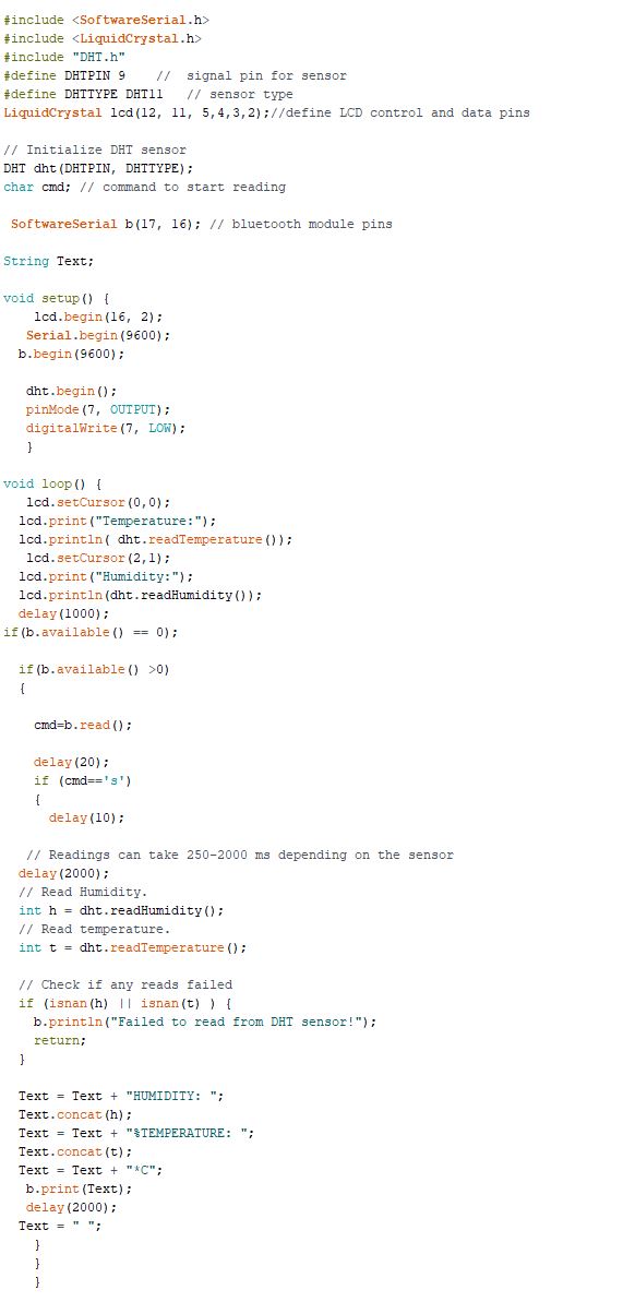 Program
The bluetooth part of the program was mostly from here. In the program I use 3 libraries. SoftwareSerial.h which allows me to make use of a software serial communication by using any digital pins on the Atmega, LiquidCrystal.h which makes it easy to use the LCD by make use of simple functions like lcd.print() to print characters on the LCD and finally DHT.h which handles the single wire communication used by the DHT11 sensor and allows us to use simple functions like dht.readTemperature() to read the temperature. My program is structured such that the LCD always displays the Temperature and Humidity values and with the help of a bluetooth app I designed in the Application programming week Values can also be read from a smartphone by typing s command in the text field (as shown in the presentation video). First, I printed the values using the LCD functions lcd.print() where I pass parameters like dht.readTemperature() or dht.readHumidity() in order to display the temperature and humidity values. Next I monitor if there’s a message available from the bluetooth by using the command b.available() (b is user defined) then read it using b.read() and if it is the ‘s’ command typed in the text field of the bluetooth app then, use b.print with the temperature and humidity as parameters (for example dht.readTemperature() for temperature) in order to print them on the smartphone screen.
Assembly and Results
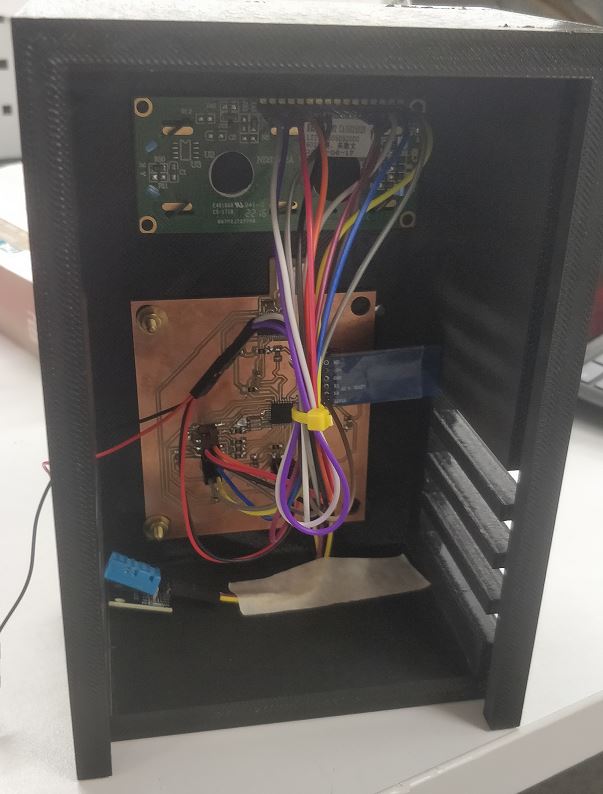 Wiring
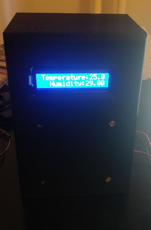 LCD output
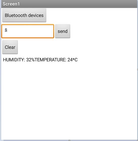 Smartphone output
Bill of Materials
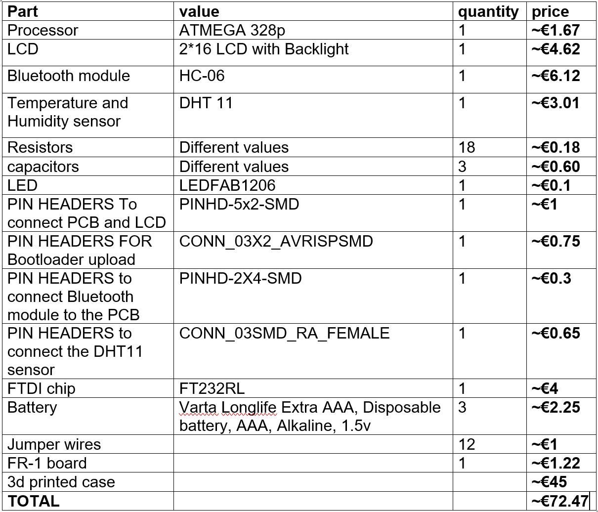 Bill of materials
- The 3D print is expensive because it is of ABS type but could be done cheaper with PLA.
License
-
I wish to make my work freely available so that other people can learn from the documentation on my Fab lab page in order to contribute to their work. For that reason I have decided to use creative commons license and under this Attribution Share Alike type of license is what I would like to use as it let’s others remix, transform, and build upon my work for any purpose, even commercially as long as they credit the owner of the work.
-
For the software part of my project I have decided to go with MIT license which allows people to freely use or modify my code.
Files
(f3d file for case /stl file for case/Logo SVG/Board Schematic/Board Layout/Code)