6. 3D Scanning and printing
This week I learned about 3D printing and scanning. For printing I designed an object which cannot be made subtractively and for 3D scanning with the help of [Xinhui] (http://fabacademy.org/2020/labs/oulu/students/xinhui-hu/) I produced a 3D scan of my face and printed it.
3D printing
Object Design
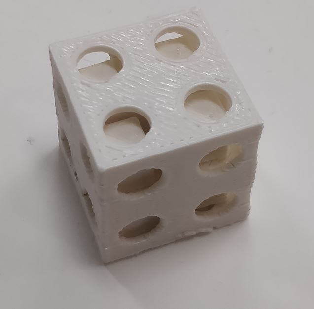
- For my design I decided to print a cube that has 4 cubes inside it, the 4 cubes inside freely move to produce cracking sounds. This object can not be made subtractively because the cubes inside need to be designed by a 3D software and 3D printed such that removing the small cubes would require breaking the container.
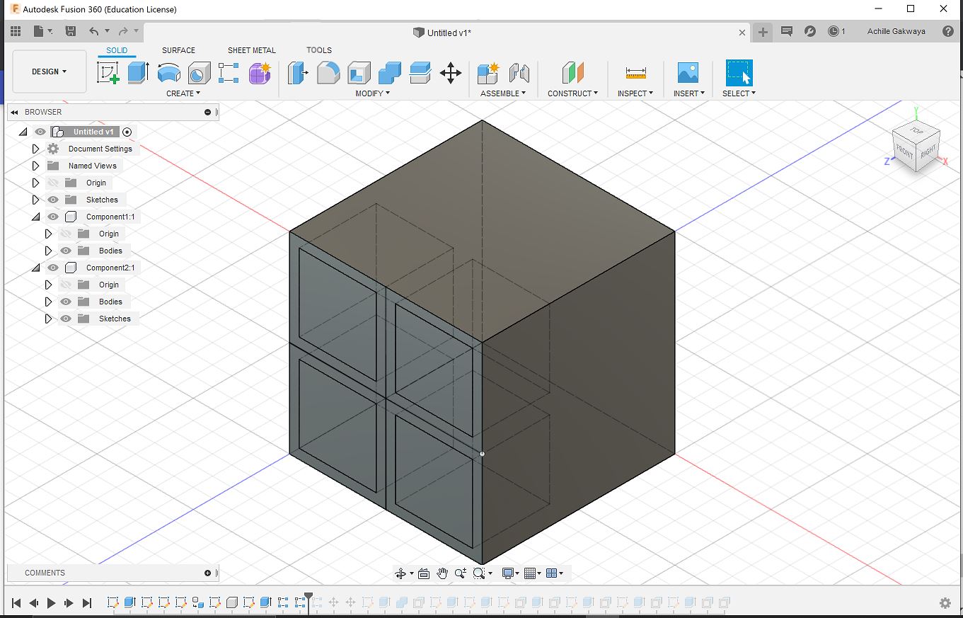
- I used Fusion 360 software to make my design. First, I started by creating a cube then I partitioned the faces of the cube into four by sketching lines (sketch>line) on them. Then I created a new component and drew a square on one face of the cube(within the constrains of the partitions) by using sketch>rectangular pattern then I selected Modify>press pull and created a cube from the square on the same face I created another cube by going to create> pattern >rectangular pattern from there I selected the orientation and number of cubes in that direction after creating the second cube from the first I then used the two cubes to create two more cubes for the lower half of the face. Similarly, I used the same technique to create four more cubes from the first four to make cubes that cover the whole volume of the container cube.
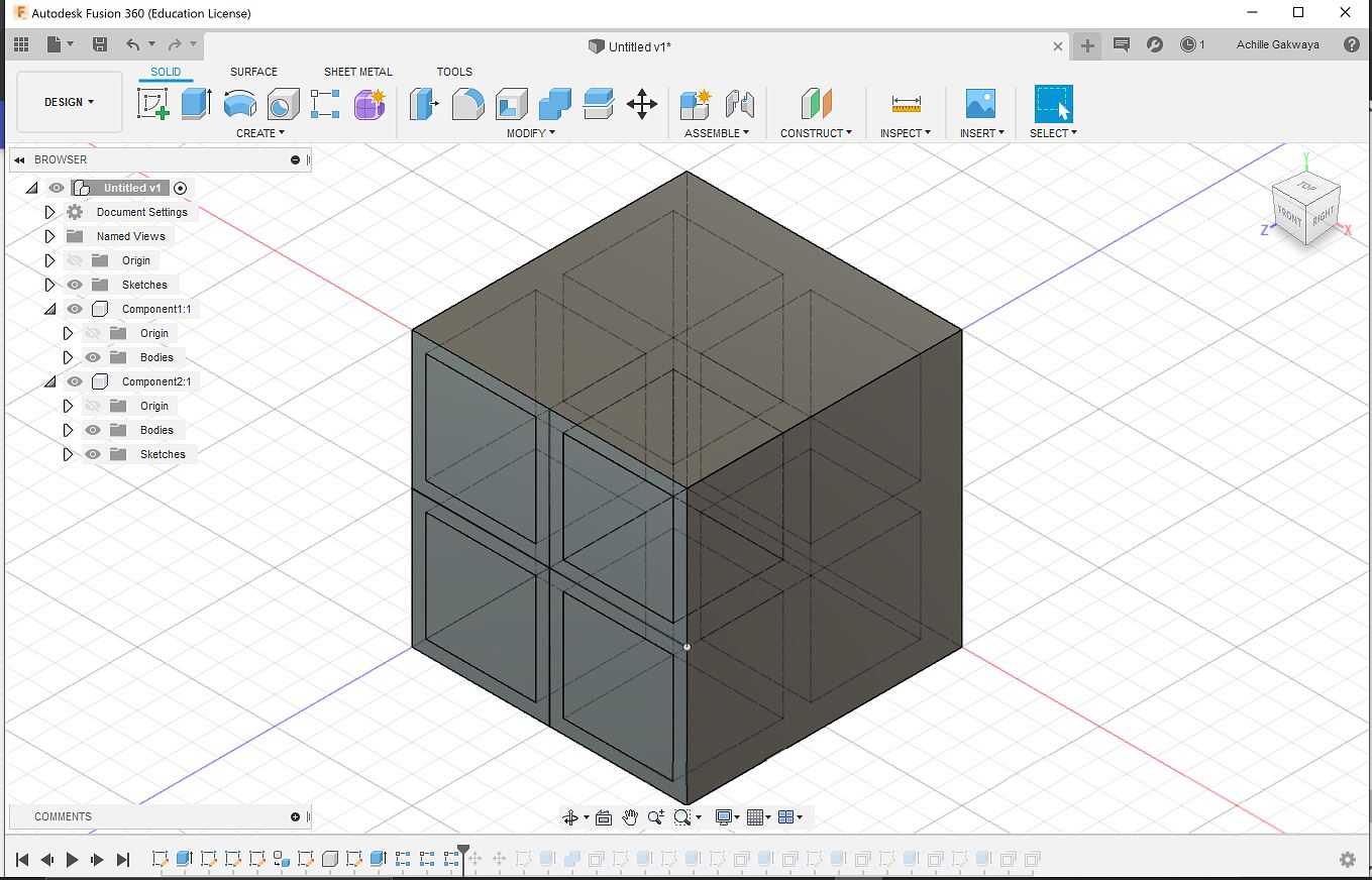
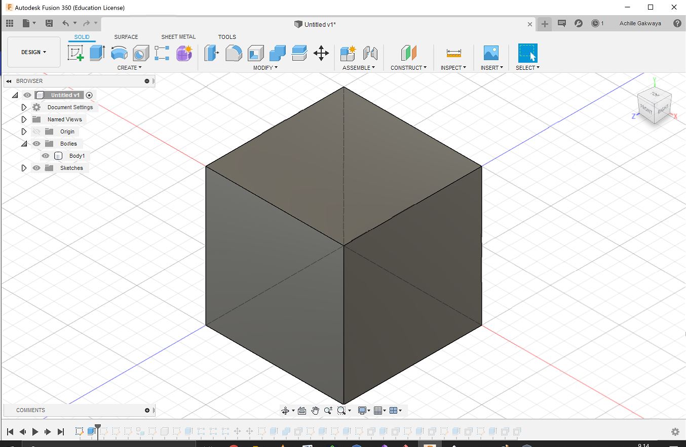 Container Cube
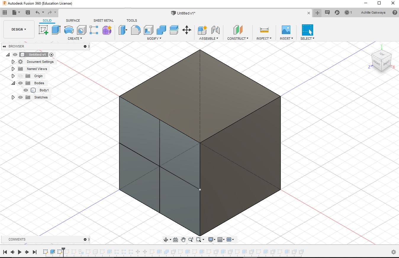 Partitioned cube
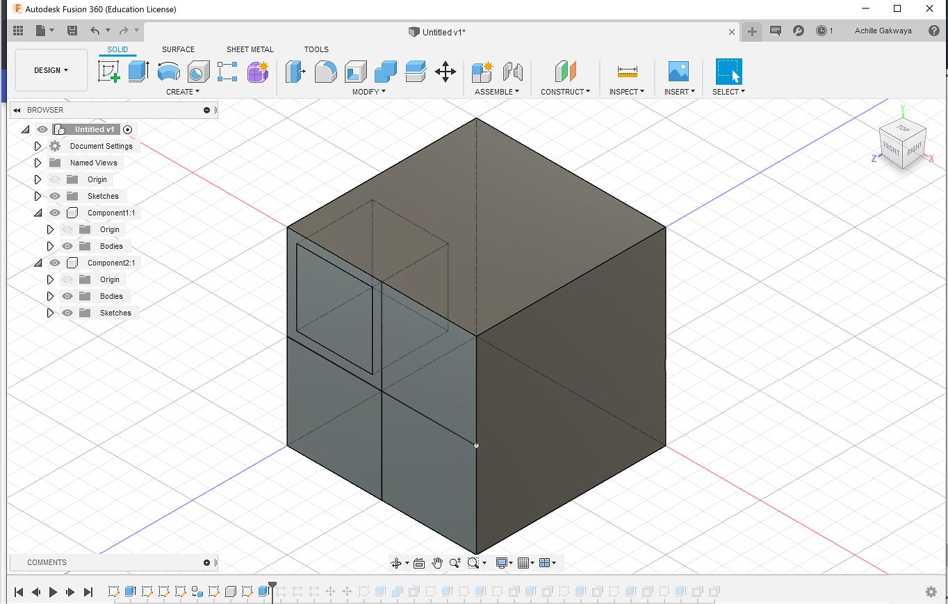 Creating first cube
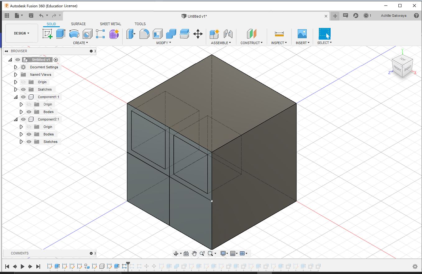 Creating second cube
 Creating two more cubes from the first two
 Creating Four more cubes from the previous four
- After this step, I slected Modify > combine then selected cut and by choosing the eight cubes as cutting tools I cut the container cube body. At this point, I had cuts in the cube that matched the exact size of the cubes and this can not allow the cubes to move freely inside the container cube. Therefore, I reduced the size of the cubes by 30% and left more room inside the cuts for the cubes to freely move. To, allow the inside cubes to be seen I created holes for each face for the inside cubes to be seen. To do this i first sketched a circle sketch> center diameter circle and used extrude to create the hole. I did the same for all the faces to obtain the final result. I then exported the stl file by right clicking the design and export then chose stl file and directory to save it in.
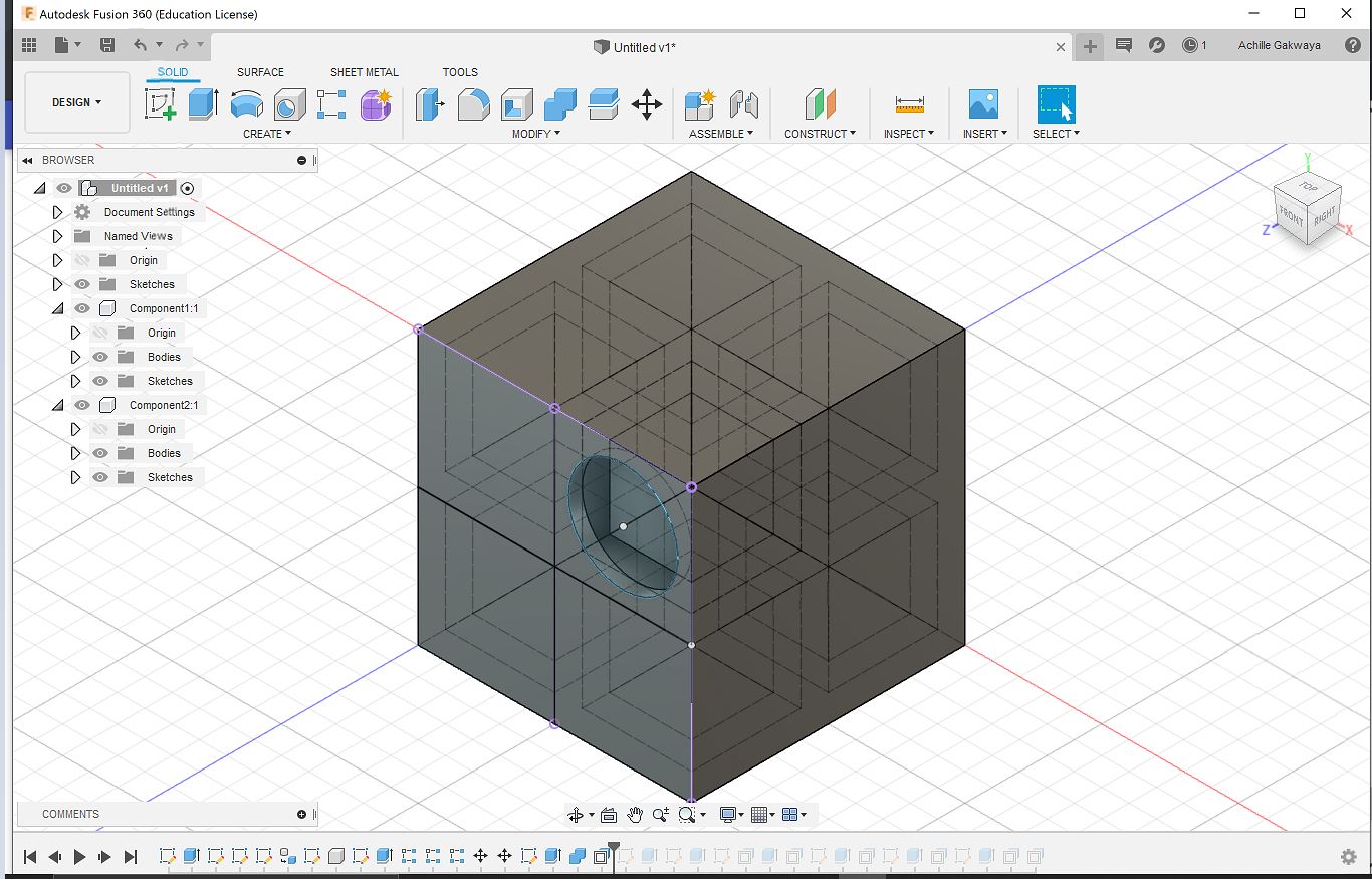 Creating circular holes
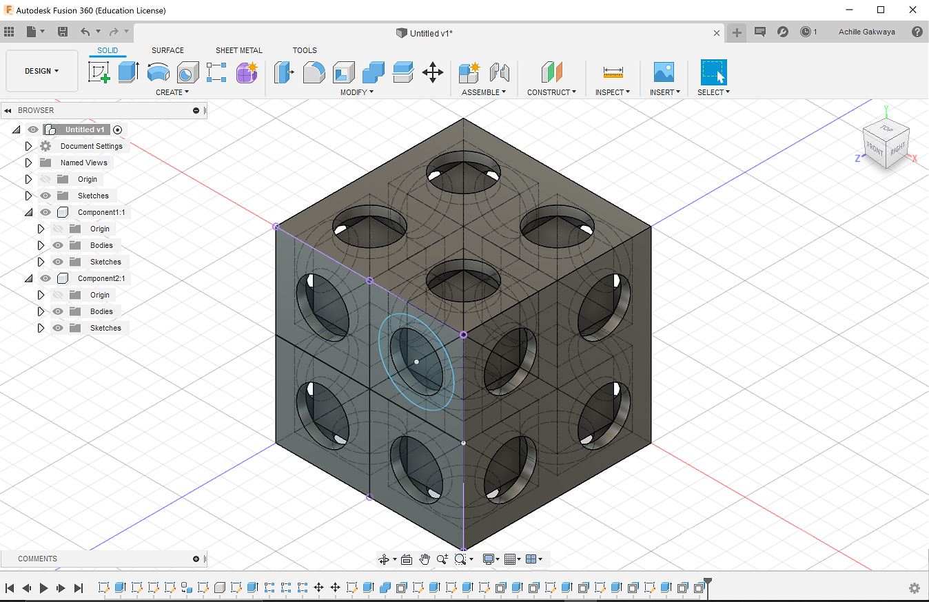 Final result
3D printing
- I used the Stratasys Fortus 380mc printer to print my design. To load my design into the printer I used GrabCAD software. First, I started by loading the Stl into the software by going to file>New project>Add models and then i located my stl file and dragged it in there. Next I proceeded to the Model settings to choose the infill percentage of the print ( which I set to 14%). Since my object was large in size I had to scale it by 50% by going to scale. Next, I viewed the support settings and maintained the SMART option so that the software calculates places where support material is needed automatically. Then, I clicked on Slice preview In order to view how the printer is gonna print my design layer by layer. After all this I saved my design and went to File>Export CMB to create a CMB file to be loaded into the 3D printer. Next, I opened the control center application which helps to send the CMB file to the 3D printer. I dragged and dropped the CMB file into the software and it showed me the dimensions of my object and how long it would take to print it. Then I clicked Build Job and the design was directly sent to the printer.
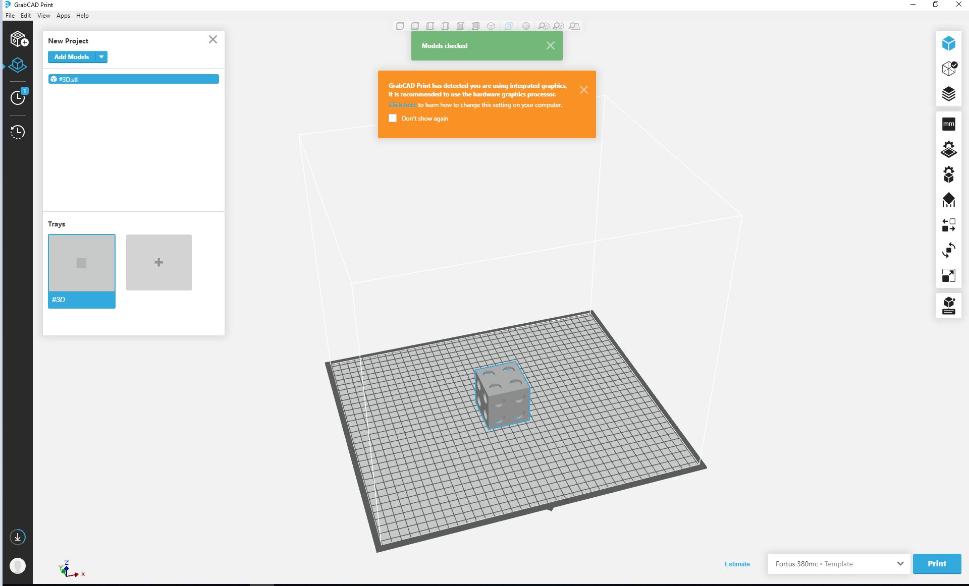 Loading stl file
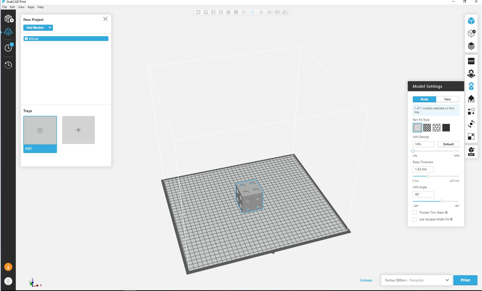 Selecting Infill
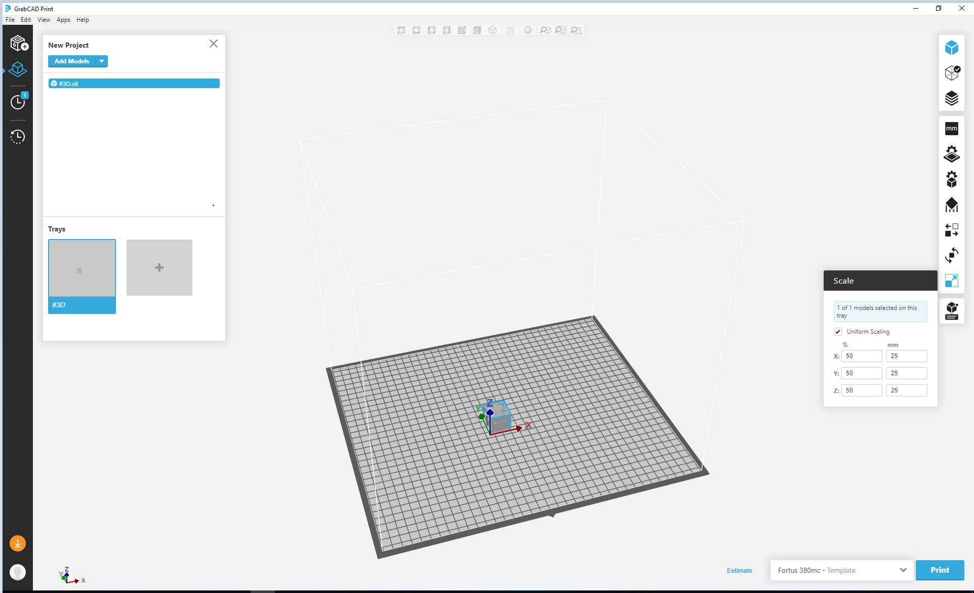 Scaling Object
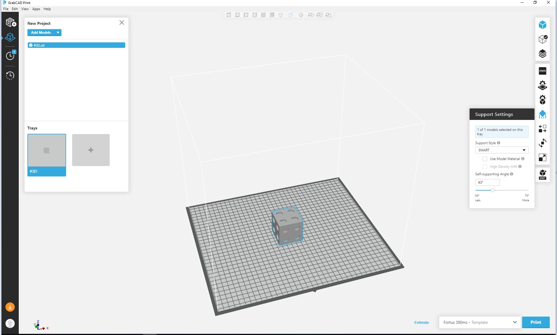 Support settings
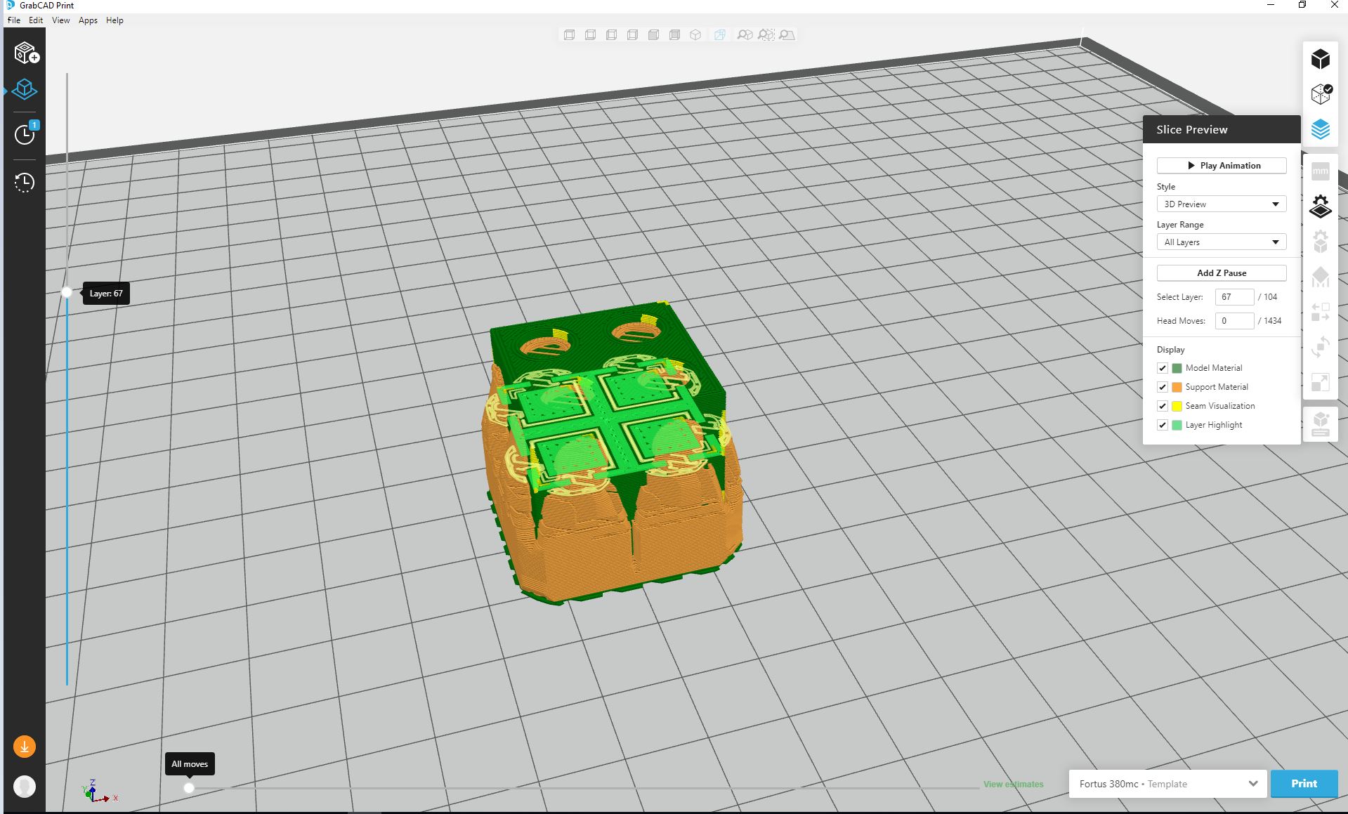 Slice preview
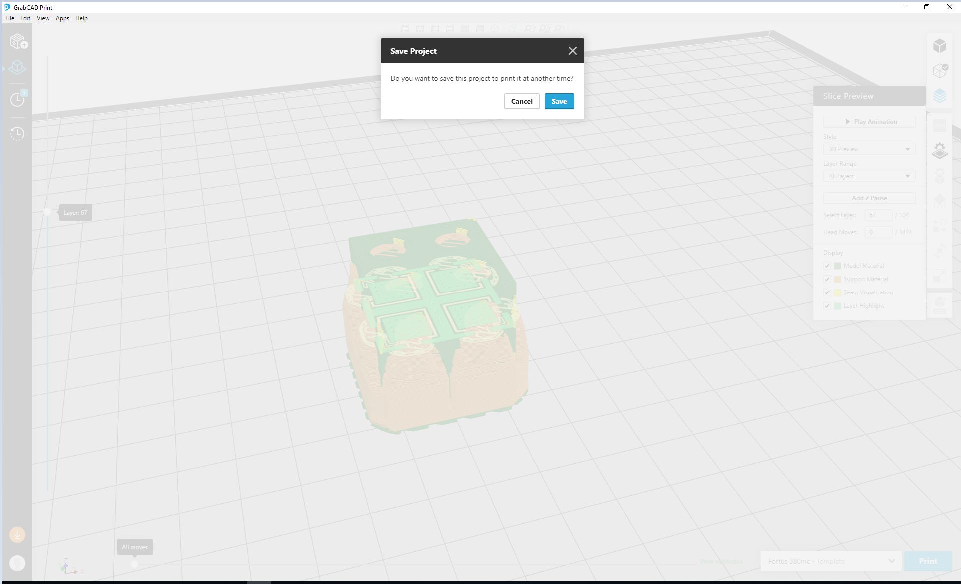 Saving File
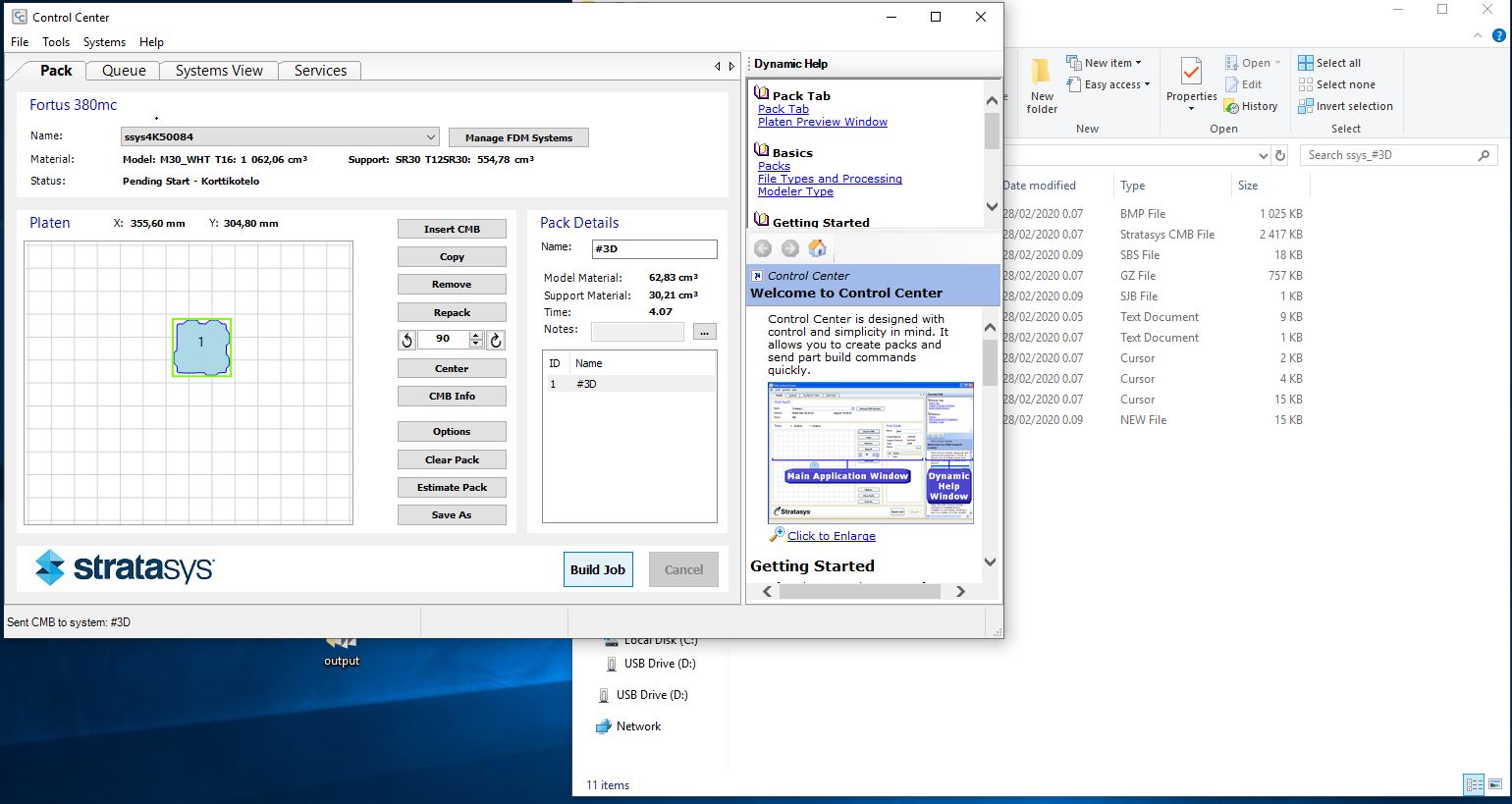 Control center application
-
The Stratasys printer has a touch menu display that helps to set settings on the printer.After I sent my design to the printer I could view it in the Queue section as shown by the display. since there were other designs sent to the printer, mine came last in the queue, to put it in the first position I pressed the up arrow key in the Queue menu (as shown in the picture) and now my design was ready to be printed next.
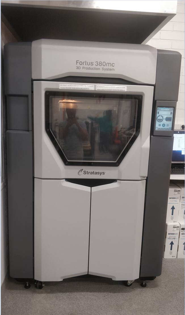 Stratasys 3D printer
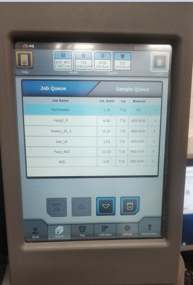 Queue
Queue
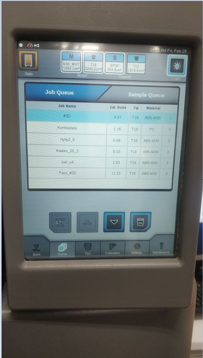 Move the design to the begenning of Queue
 -
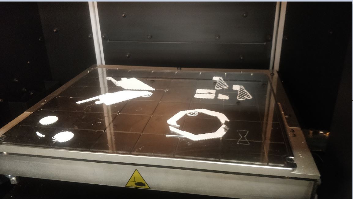
Now that my file was first in the Queue I had to get the 3D printer ready and print my design. To do this I fixed in the sheet on which the print is done. to insert the sheet it’s better to align it with the pins on the corners of the printer so that the printer recognizes it, once the sheet was placed I closed the door of the printer. Initially, the printer will not recognize the sheet because it gets fixed after a while by the vacuum inside the printer. When, the sheet is not yet fixed the printer displays the message Insert the build sheet on the display, and after some time when the sheet is correctly fixed the message reads Ready to build #3D. At this stage, next I had to place where on the sheet I wanted my design to be printed, I then selected the spot (as shown in picture) then pressed Ok. Next I pressed on the Build menu and there I saw details of my design and the time estimate for my print, then I pressed on the Play sign(as shown in picture) and the printer started printing.
 Sheet not fixed
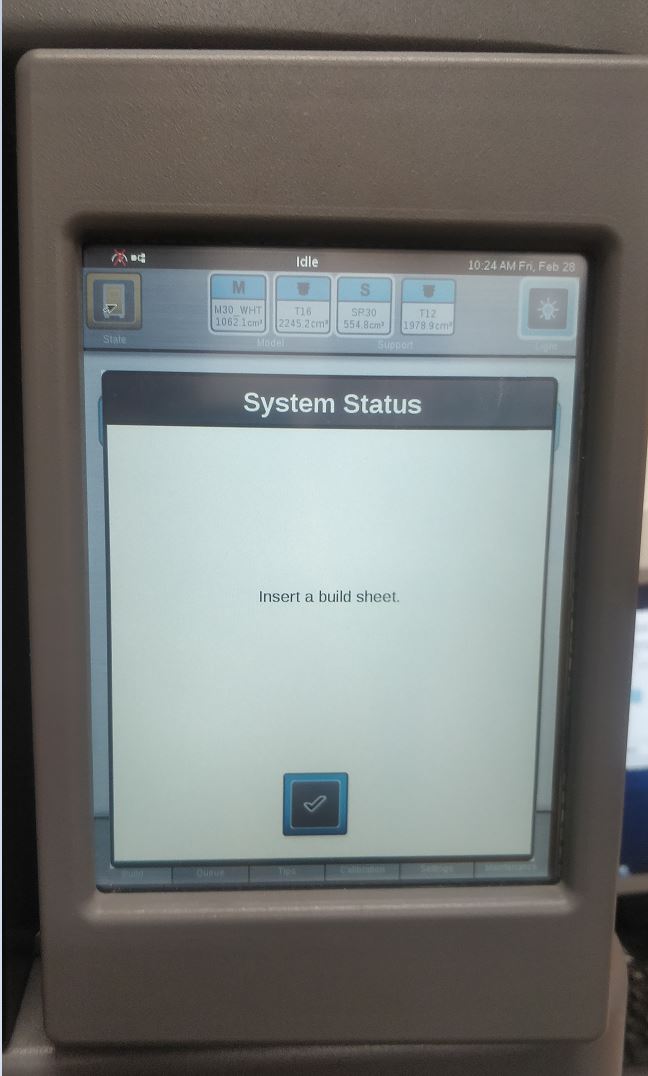 3D printer detects that the sheet is not fixed
 Sheet fixed
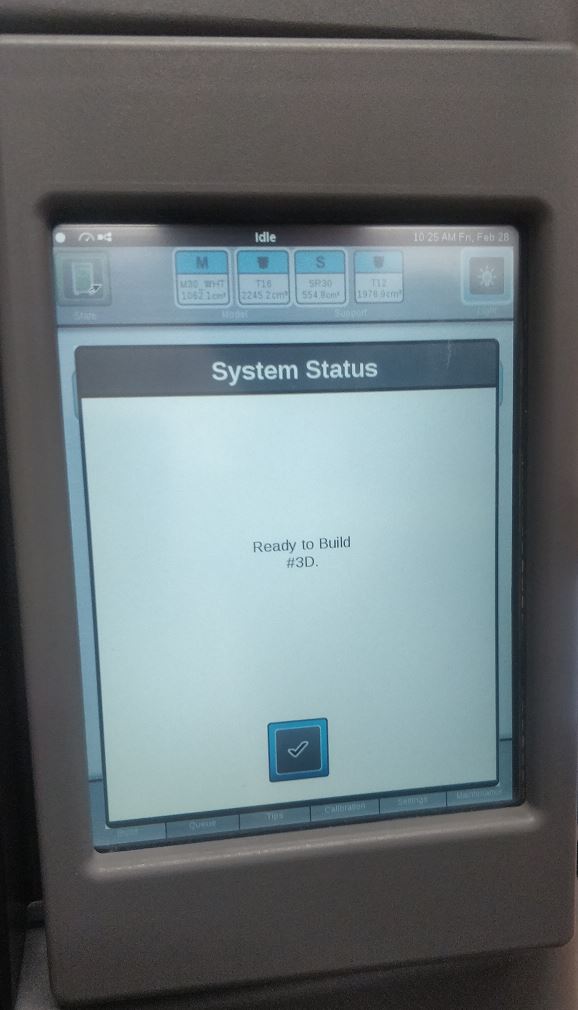 Screen after sheet is fixed
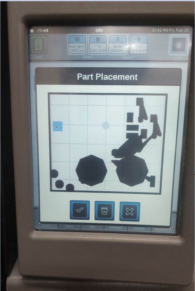 Placement of the design
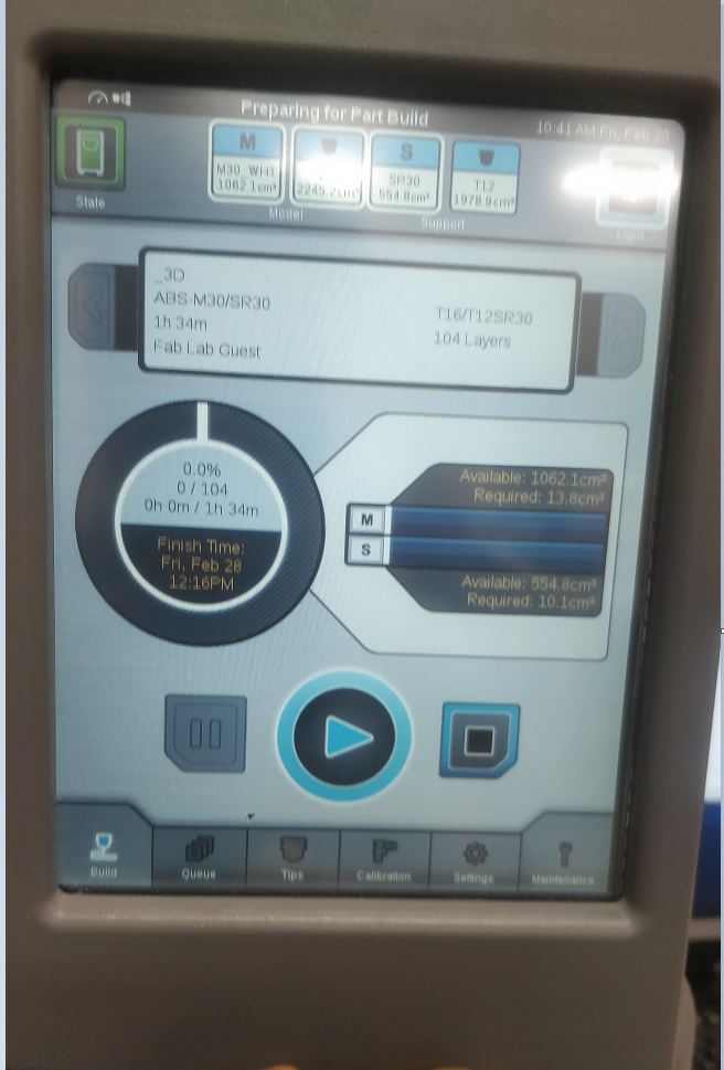 Starting the print
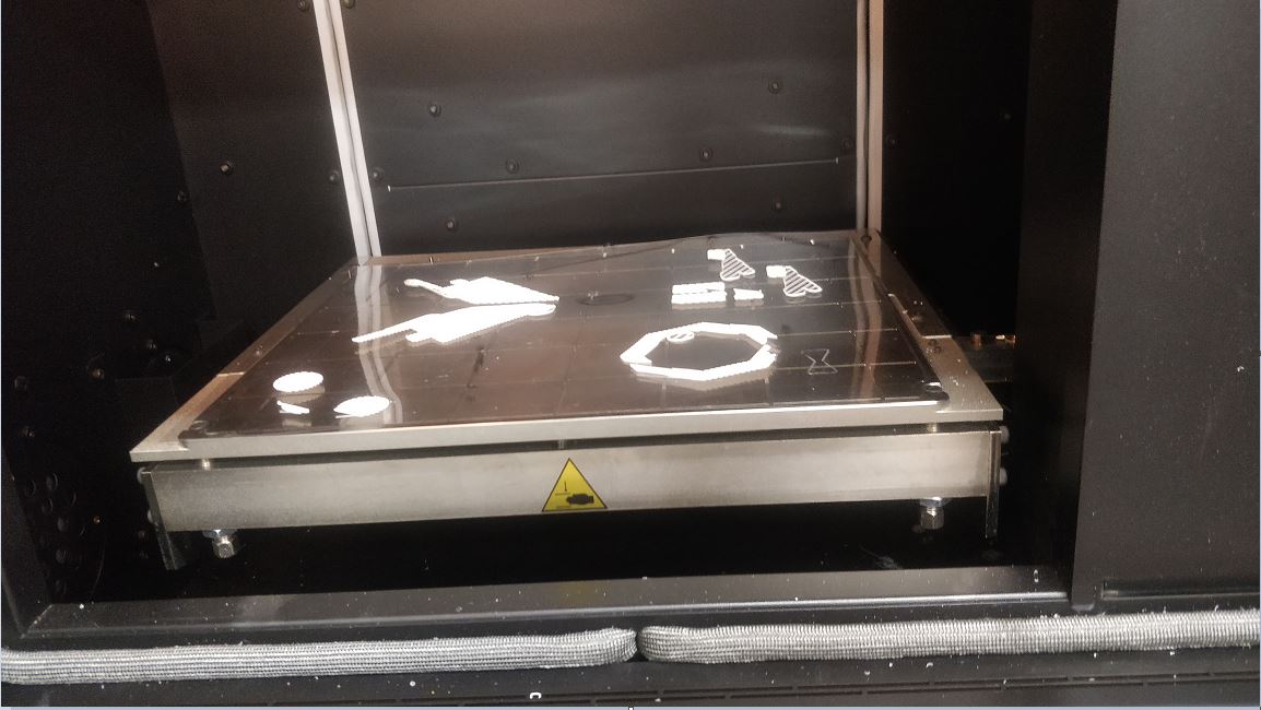
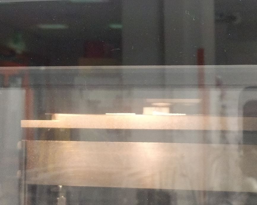 3D printer at work
- After the printing was done I removed the sheet from the printer, I did this with gloves because the inside of the printer is hot. After that I removed the print from
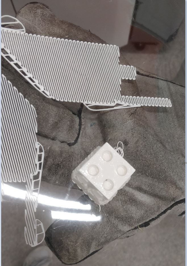
the sheet and it was easy by just pulling it away from the sheet(the sheet is that smooth). Next, I removed the base material and then put the print inside a sodium hydroxide
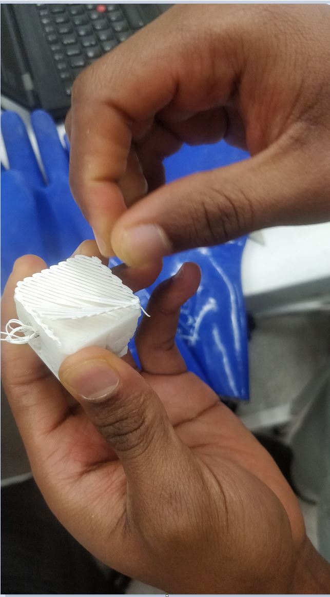
solution (also known as Lye) which dissolves the extra support material from the design and leaving the original design behind. The design has to be left overnight in the solution but again it
depends on the size of the design and can take longer. After two days, I removed the design from the solution, washed it and it was same as the intended design despite minor
printing defects.
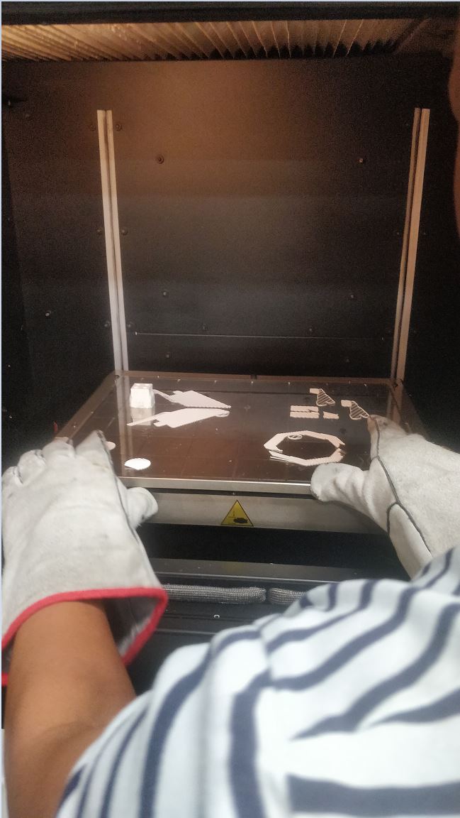 Removing the sheet
 Removing the print
 Remove base material
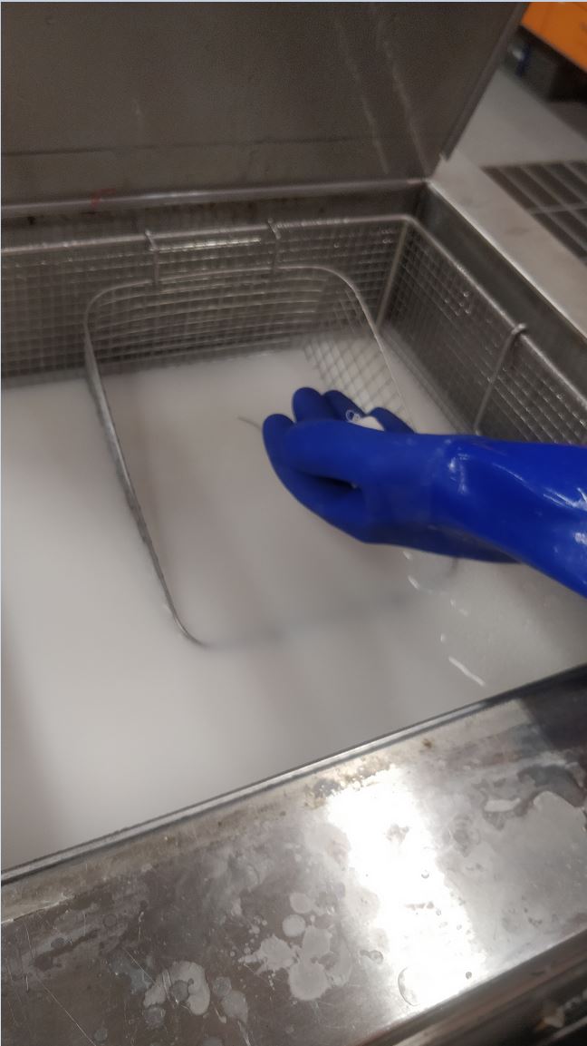 Putting print in solution
 Finalproduct
*My 3D printing eperience was really good, I got to learn new things and the process was relatively easy and straigthforward. I used to see people do 3D printing and thought it was difficult but now I can do it myself easily.
3D Scanning and Editing
- I used the sense 3D scanner(shown in picture) to scan my face then I edited the output and printed it. My classmate [Xinhui] (http://fabacademy.org/2020/labs/oulu/students/xinhui-hu/) was holding the scanner While I rotated in a chair in order to allow her to capture my face in 360 degrees. To use the sense 3D scanner is not complicated first, it needs to be plugged in a computer’s USB port then the Sense software installed on the computer detects it and from there choose what your scan will be, either a human or an object. In my case, I selected human because I wanted to scan my face After this, the scanner starts scanning and in the application it shows which part is being scanned and slowly rotate the object to cover it all. After the Scan was done I saved the file as .obj file and used the windows 3D viewer to view it. as shown in the picture the final obj file was decent but not perfect because it had holes in it and hence needed extra editing to be able to be produced in a form that can be printed by a 3D printer.
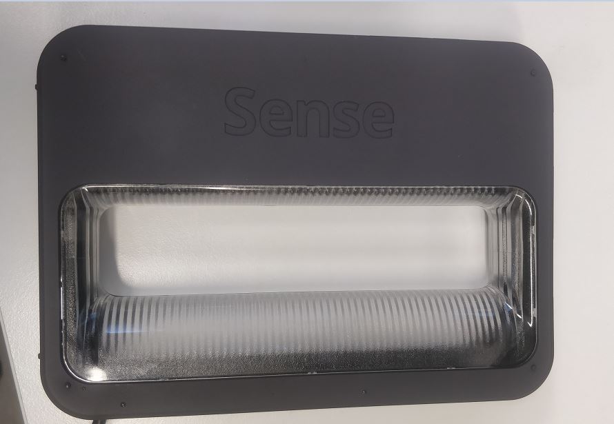 Sense 3Dscanner
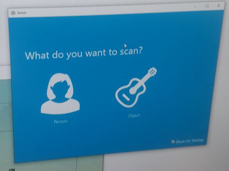 Sense application
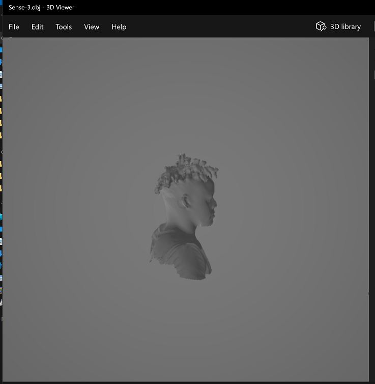 Obj file
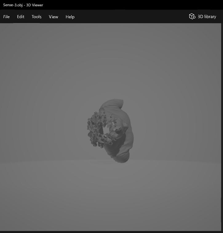 Imperfections in 3D scan
-
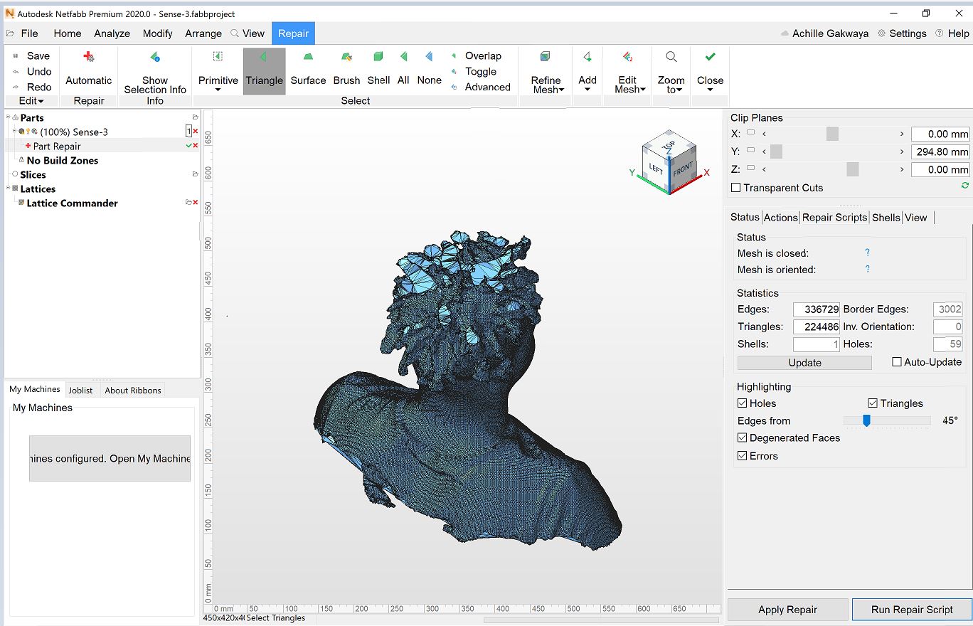
In order to edit the scan I used Netfabb,The process was easy. I first, dragged and dropped the Obj file int the software and after loading it on the pop up menu I selected Add parts and the design was successfully imported into the software. Next I clicked on the top menu with red cross that says Repair part then from the bottom right corner I chose Run repair script (as shown in picture). The script is designed to repair the part automaticlly without the need to do manual modifications. Next, from the pop-up menu I selected Default repair and cliked Execute. After this my design was repaired and the holes were filled as demonstrated in the pictures. Then, the last step was to go to home Export project as stl file and this created an stl file(shown in picture) which was ready for printing.
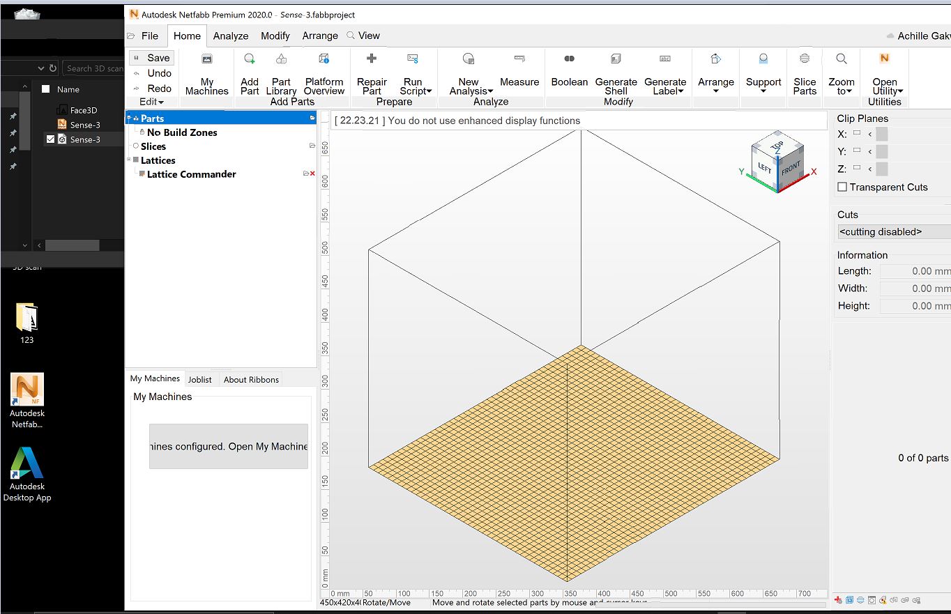 Drag and drop Obj file
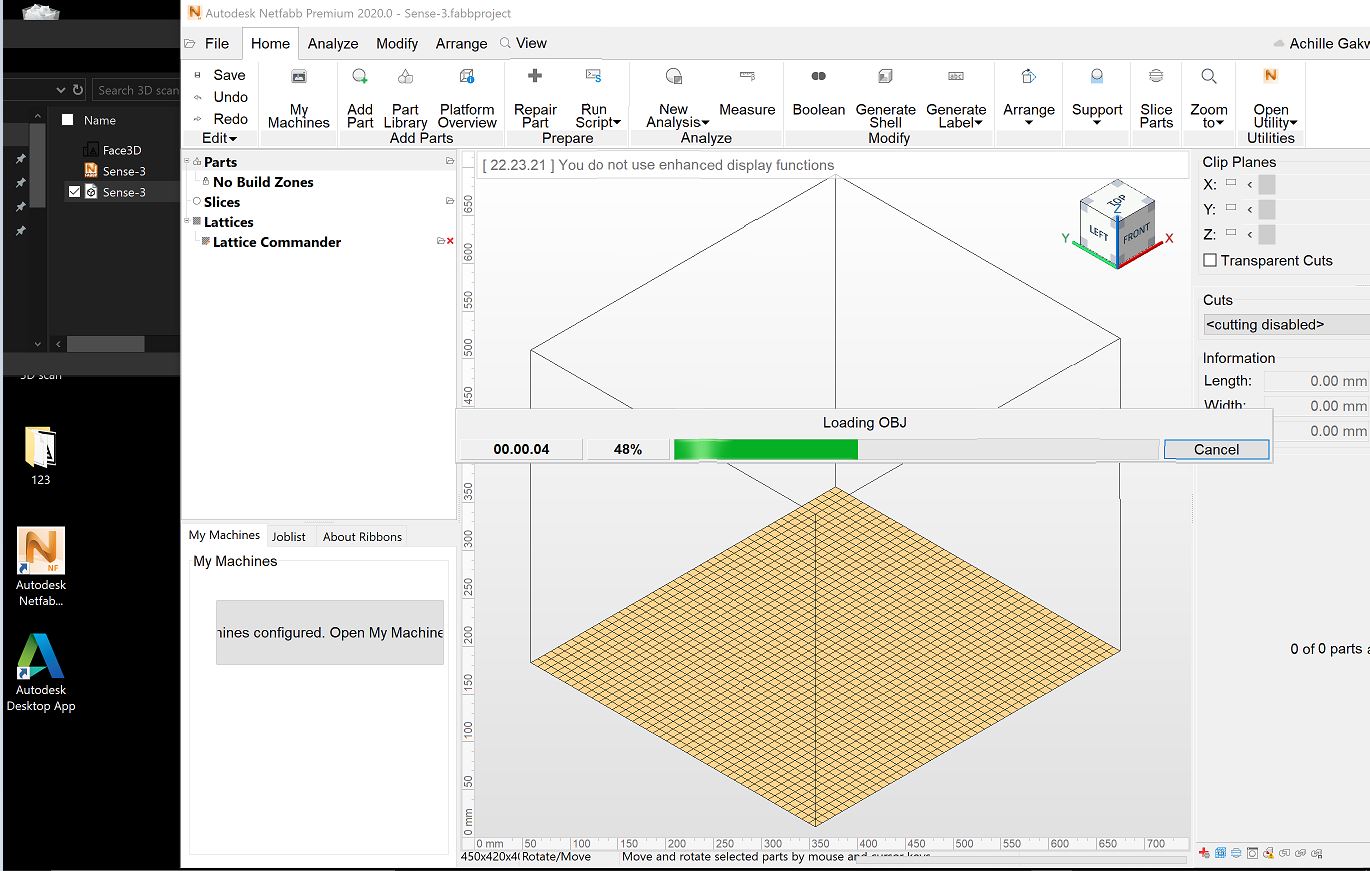 Loading obj file
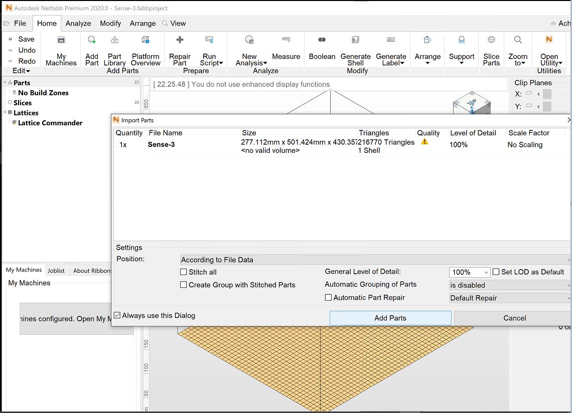 Add parts
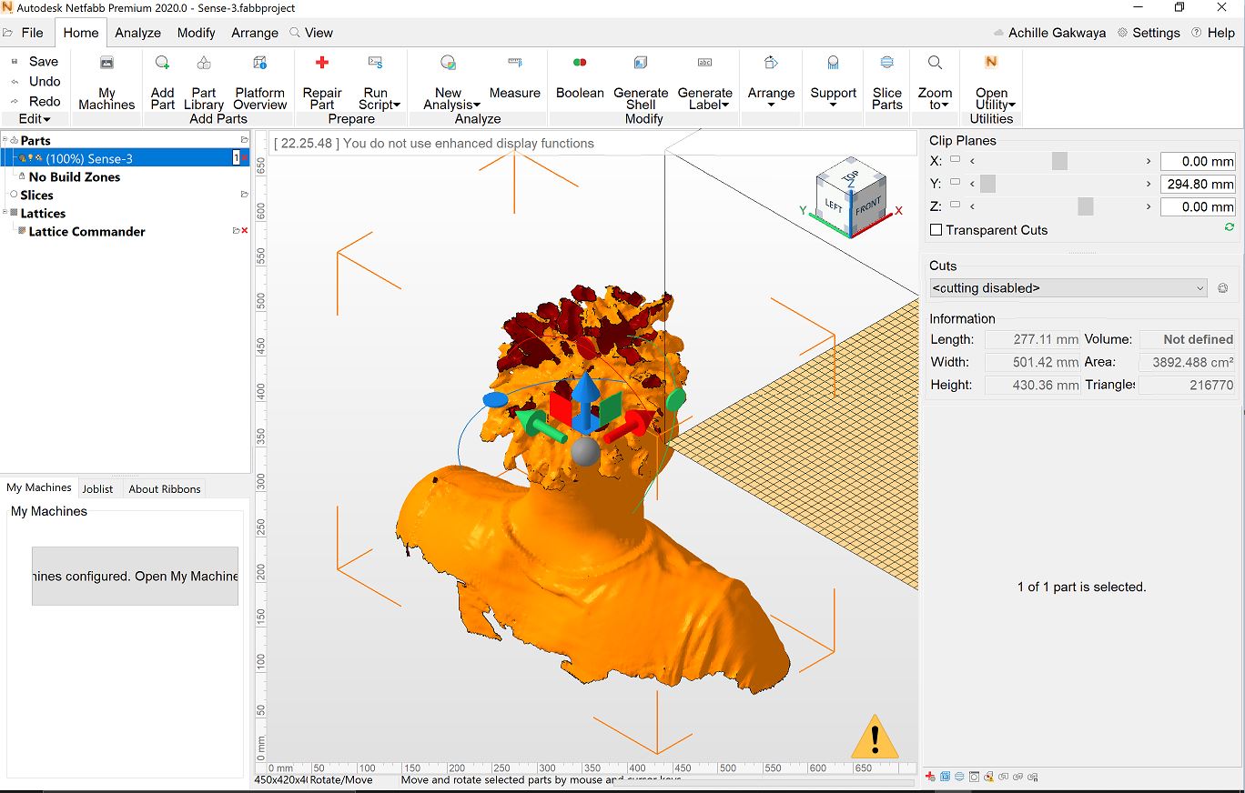 File before repair
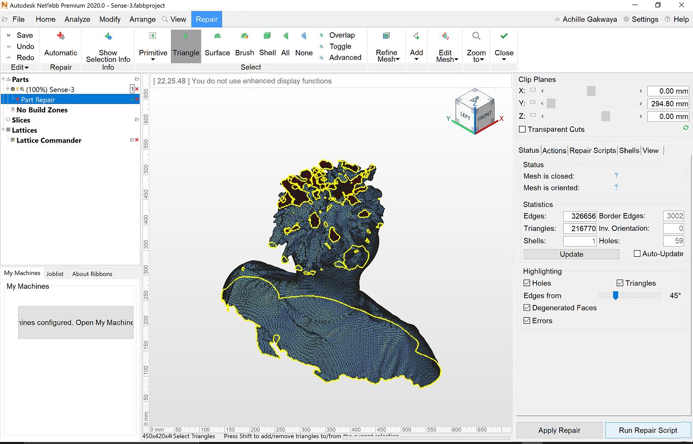 Run repair script
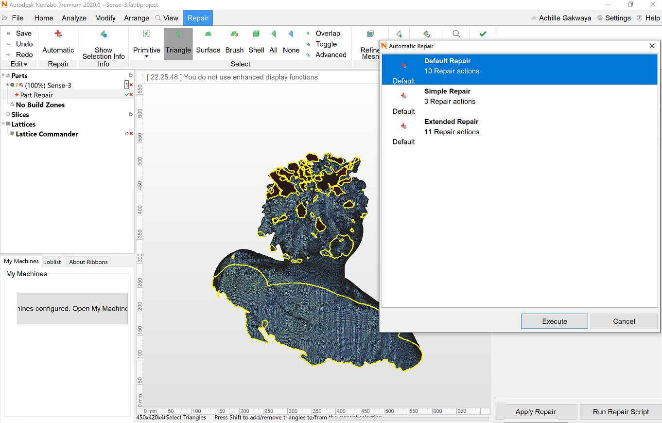 Default repair
 After repair
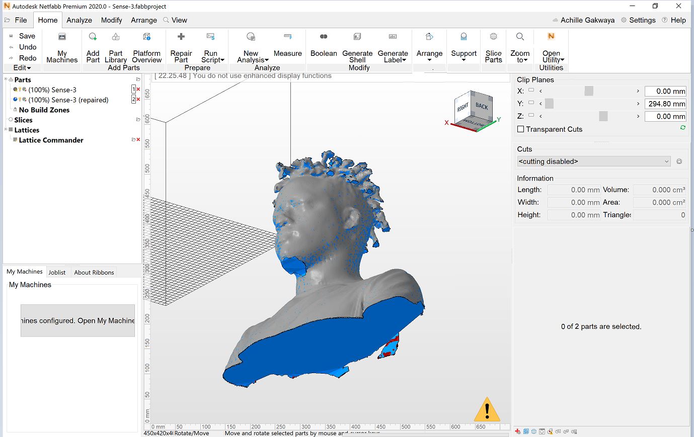 All the holes are filled
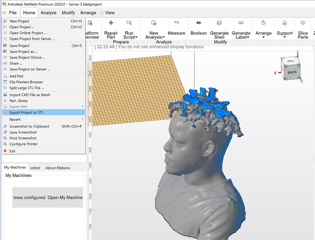 Export to stl
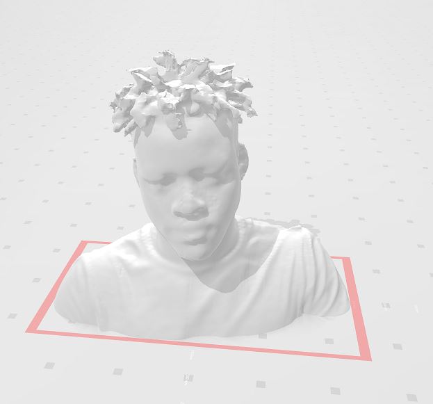 Final stl file
 -
Finally, I printed my scan and it looked pretty decent.
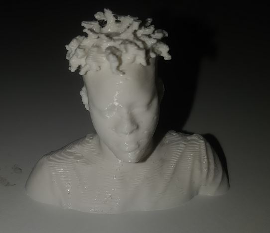 Final scan Print
-
My 3D scannning experience was really educative and was an opportunity for me to use a technology which I have never used before. The process was easy Just set settings and point the sense scanner onto the target and rotate. Moreover, I wanted to learn more by producing a 3D print out of my scan and from there I saw need to edit my scan so that it’s suitable for printing and by using an editor tool I also learned more. Finally, the printing was easy because I had done it before successfully. Afterwards, I was really excited to have a very good 3D print of my face which is cool!
-
I faced a challenge of reducing my 3D scanning .obj file but with the help of my local instructor I was able to reduce it. It was done by using Fusion 360 Then from there I opened the .obj file > Switch to the mesh environment > Select Body > Modify > Reduce > Reduce Type:Adaptive, Reduce Target:Density, reduce the density by moving the bar > save as .stl and my file was reduced to 800kb which I further compressed using .zip compressor.
Group Work
In the group work I had the opportunity observe how accurate printers can be to the smallest details for example an inclined print, a circular print and more, the group work can be found here