Week 5: 3D scanning and printing
Week five's assignment was to design and 3D print an object that could not be made subtractively. Also to 3D scan an object. Group assignment was to test design rules of the 3D printers.
Group assignment
Our group for this week was myself, Achille, Hannu, and Jari to test the design rules for three different 3D printers existing in our FabLab. We used Thingiverse's test file. We ran the file with three 3D printers found at our lab.
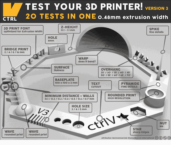 Layout of the test file.
Used printers were:
- MakerBot: Replicator 2
- Sindoh 3Dwox
- Stratasys Fortus 380mc
Local instructor Mikko and Behnaz went through settings on the software used to print. It took about an hour for every printer to finish the job. Used materials were ABS with Stratasys and PLA with Sindoh and MakerBot.
ABS is Acrylonitrile Butadiene Styrene. ABS is one of the first materials used in 3D printing and it is still very popular due to low cost and good mechanical properties. ABS has good impact and wear resistance. It can also withstand high temperature which makes it good choice for outdoor and high temperature uses.
PLA is Polylactic Acid. PLA is also cheap and can be printed on low temperatures. Because of this it is considered good material when learning to use 3D printers. It is also environmentally friendly material.
Stratasys Fortus 380mc
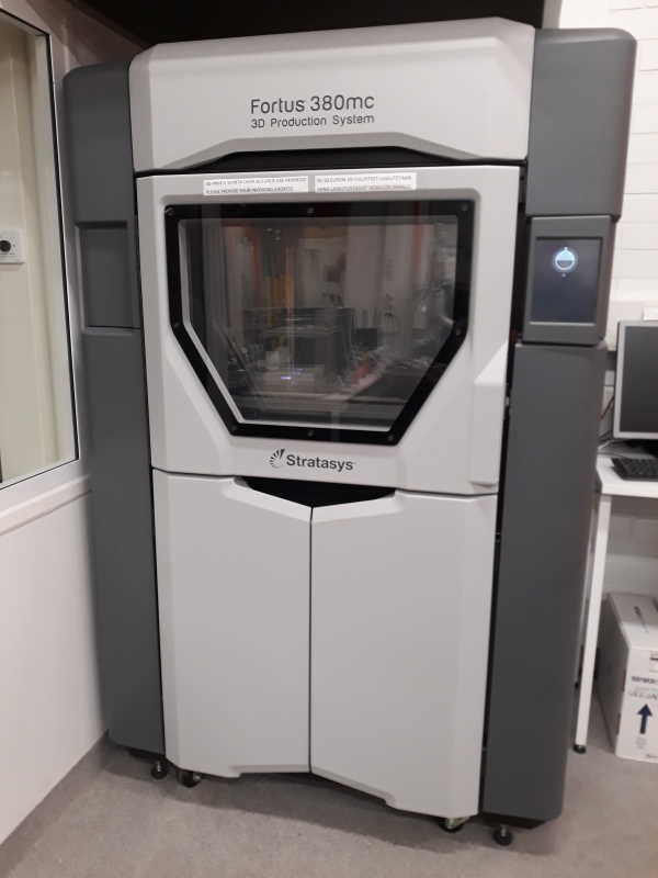
Stratasys is the biggest 3D printer at our lab. It can be left to operate through night without supervision. Bed is so hot that it is advised to use gloves to pick it up after print is done. We have a lye tank to remove a support material for prints made by this one.
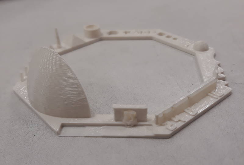
Close up from Stratasys' thingiverse test.
Sindoh 3D wox
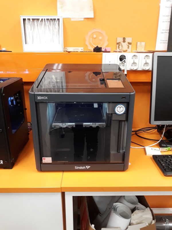
Sindoh can be paused or stopped by using touchscreen on the device. It is also possible to resume the work after pause. Bed is magnetic and very flexible to easily take off the print.

Close up from Sindoh's thingiverse test.
MakerBot: Replicator 2
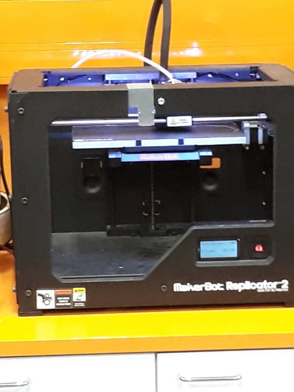
MakerBot is the only open style from these three. This one made the print a little bit faster compared to other ones. This specific machine has also interesting fact that it only works with pink material at our lab.
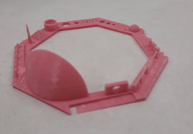
Close up from MakerBot's thingiverse test.
Results
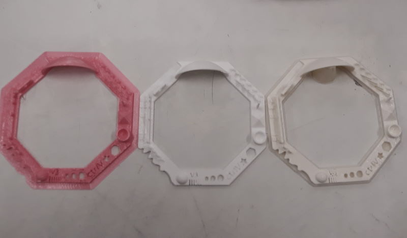
All of the prints next to each other. From left to right: MakerBot, Sindoh and Stratasys.
After printing all three we went through results. We made a table to see the results.
| Part | Stratasys Fortus 380mc | Sindoh 3Dwox | MakerBot: Replicator 2 |
| Wave, Rounded print | Pass | Pass | Pass |
| Star, Sharp Edges | Pass | Pass | Pass |
| Name, Complex Shapes | Pass | Pass | C and T are connected |
| Minimal Distance: 0.1 - 0.7 mm | 0.4 mm | 0.5 mm | 0.2 mm |
| Z-height | Pass | Pass | Missing lowest step |
| Wall Thickness: 0.1 - 0.7 mm | 0.5 mm | 0.6 mm | 0.5 mm |
| Sphere, Rounded Print 4.8 mm height | Pass | Pass | Pass |
| Sphere Mix, 7 mm height | Pass | Pass | Pass |
| Pyramid, 7 mm height | Pass | Pass | Pass |
| Warp, does it bend? | Yes | Yes | Yes |
| Spike | Pass | Pass, but low quality | Pass, but low quality |
Stratasys seems to have best overall quality of these 3. This was especially noticeable in Spike. MakerBot was able to get best result from Minimal distance test. Wall Thickness is pretty interesting because none of these got a great result. Sindoh's results seem to be weakest in comparison, but the quality was still good enough.
3D printing
My inspiration for this week's assignment came from Antti's rotating bed for soldering except made with 3D printer. His one is made with laser cutter from MDF. This helps when soldering since the board is taped on the bed and you can rotate it easily when required. Although this would be not be efficient way to create it I just could not get idea out of my head. Just in case if it would not work as inteded I had a backup plan.
I used Fusion 360 to make designs this week. It's been my choice this far in academy.
Designing with Fusion
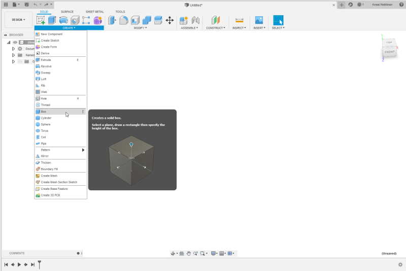
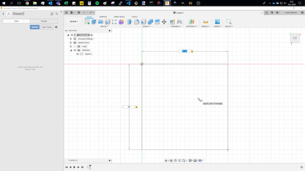
First I created Box. Box can be created by opening Create dropdown-menu. I set width and length to 20mm.
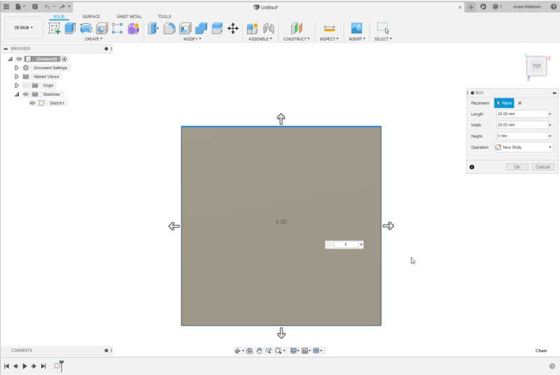
I set height for the box to 5mm.
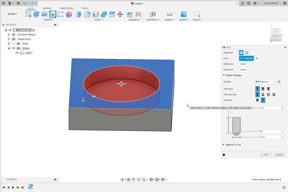
After setting up the Box it was time to create a slot for the rotating bed. I set distance for the upper layer of slot with a hole tool to 1mm and diameter to 15mm.
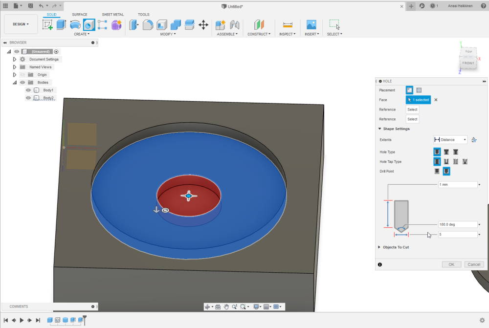
Used hole tool again to create space for a middle section of the slot. This section will be narrow to keep whole rotating bed attached to the base. Distance was set on 1mm and diameter to 5mm.
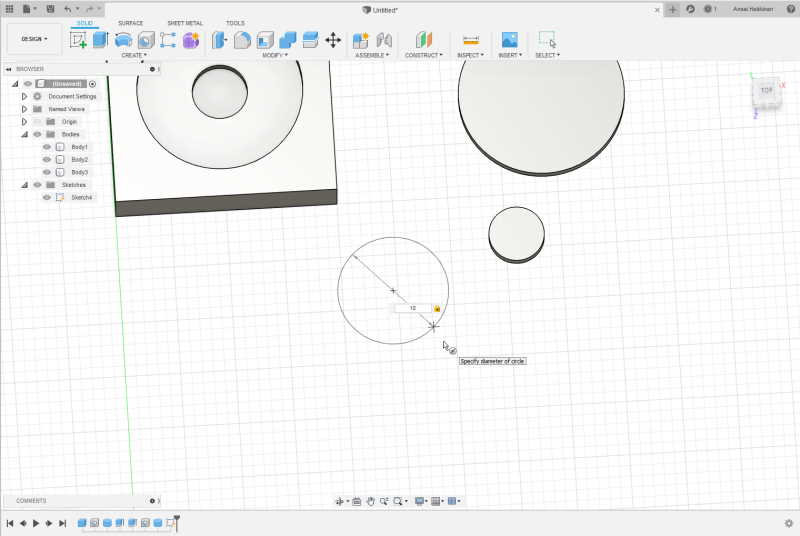
Next I created three circles. These are parts for the rotating bed. To make bed to be able to move I made it's parts smaller than the slot. Height of each part was at this point set to a 1mm as well , but diameter 0.2mm less than the slot. For the bottom part diameter was set to 9.8mm.
I made a circle with 10mm diameter and placed it 1mm below the last hole. With this object I will create last hole.
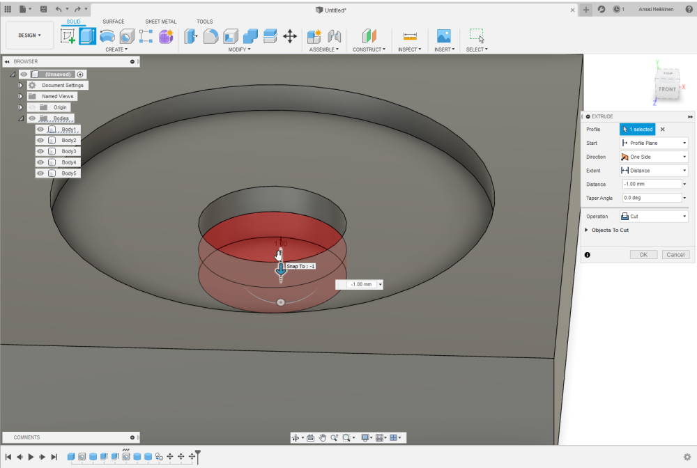
Made a hole to reach the bottom. Distance was set to a 1mm. First I tried to skip this part and just use Extrude, but I had problems with it. By doing this it worked as I had planned.
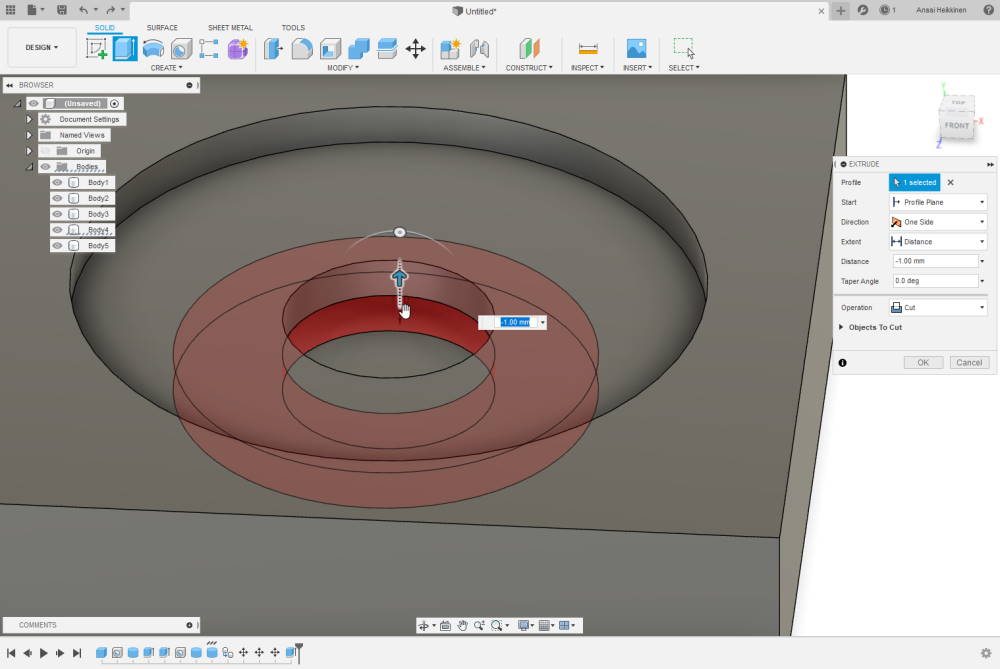
Extrude (shortcut E) was used to create wider hole at the bottom. Since height of the part is 1mm so this was also the distance that extrude was used with. Purpose of this is to keep the base and the rotating bed together.
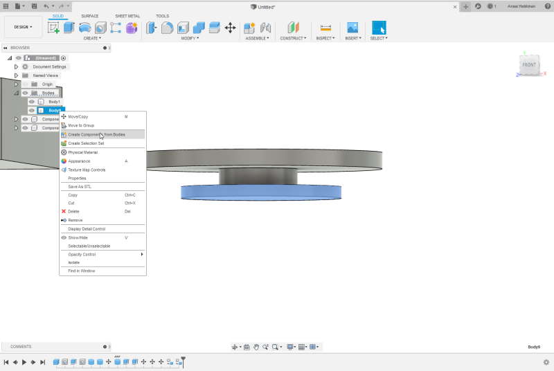
I changed bodies of the parts to own components. I find it easier to move them this way.
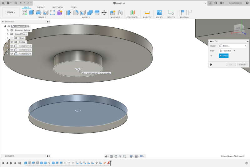
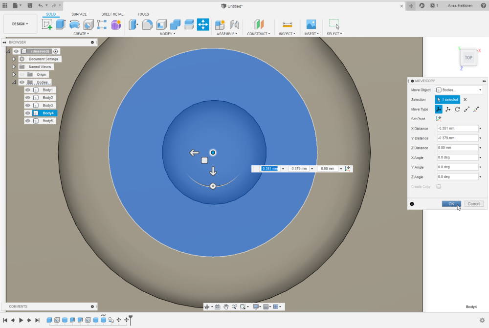
Aligning parts so all of the them are set correctly. This can be done by selecting align tool and selecting center of two planes.
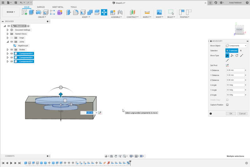
After aligning I tested that it fits into the slot by moving all of the three parts. Shortcut for Move tool is M and it can be found from Modify dropdown menu.
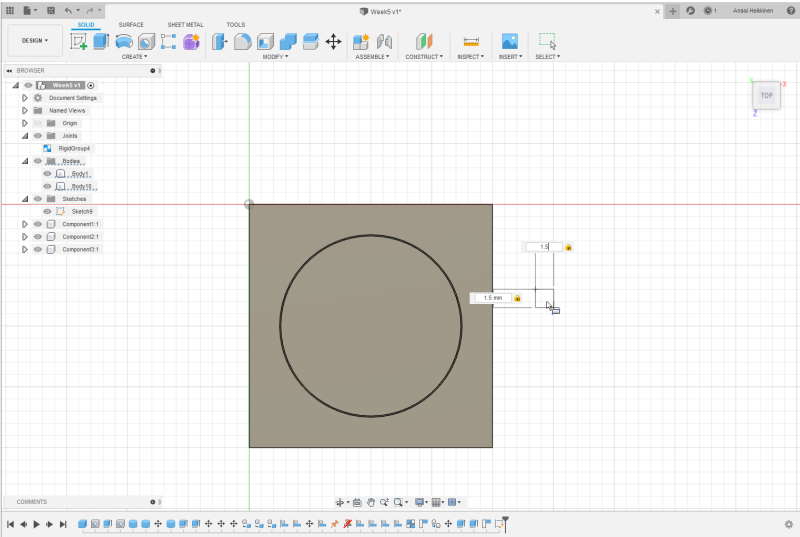
Nearly forgot to create anykind of handle for rotating. Small Box was my choice for this purpose. I set width, length and height to 1.5mm.
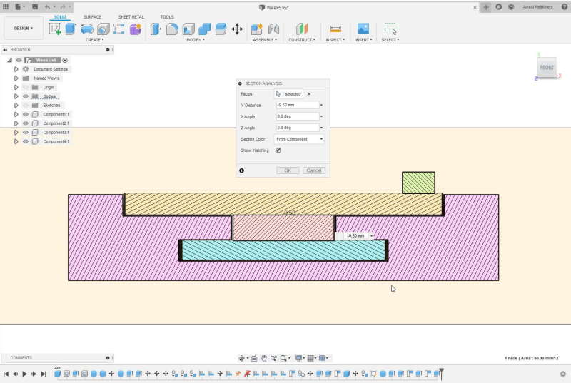
It was time to check whole structure with Section analysis. Section analysis can be found under the Inspect drown-down menu from the top toolbar. I made sure there was at least small gaps between objects. Although these were way too small gaps which can be noticed after first 3D print.
3D printing
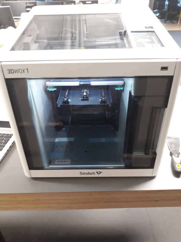
I used Sindoh's 3Dwox1 printer at BusinessAsema instead of ones at university. We have only one type of 3D printer at BusinessAsema.
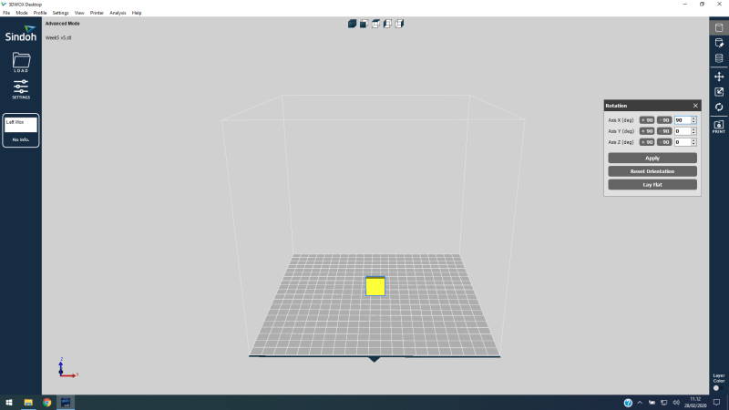
I exported from Fusion 360 my 3D-design as .stl because it is widely used format with 3D printers. To use printer I opened 3Dwox desktop -software. This software is straightforward to use. File can be opened by pressing Load and browsing through folders. First I rotated the object 90-degrees in X axis.
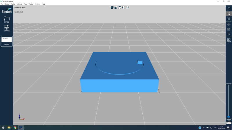
Next I checked if software would advice to use support material.
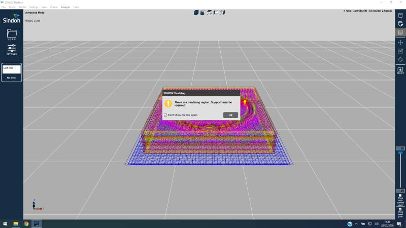
When opening changing option I got pop up which stated that suport material is required. Support material between the bed and object is usually good practice because this way it will be straight even if bed is not flat. After this I pressed Print-button from right-ribbon.
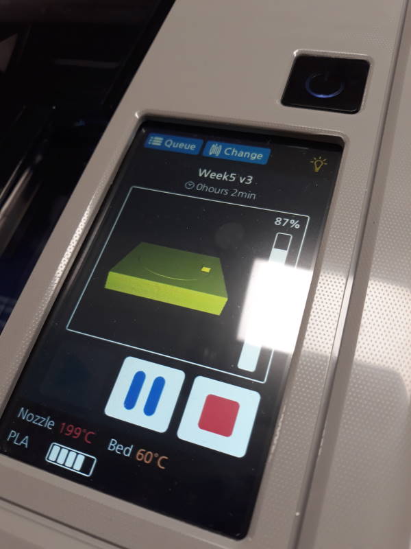
This is the user interface at 3Dwox1. Power-button is above the touchscreen. Touchscreen has useful information such as estimated time and temperatures.
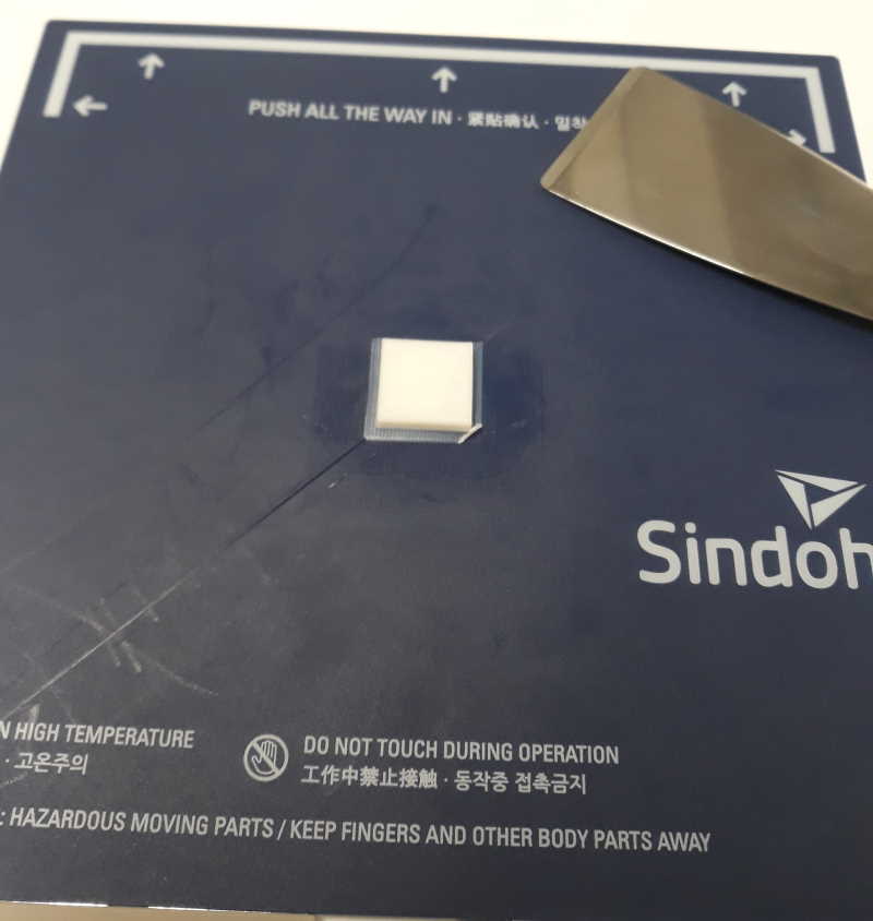
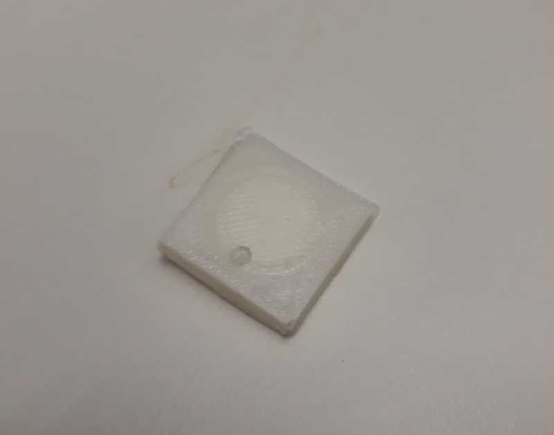
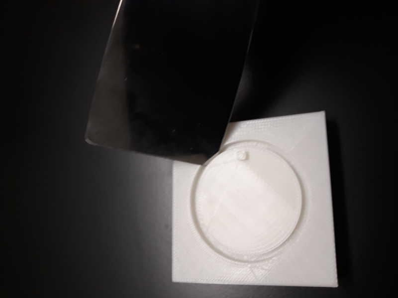
I used chisel to detach object from the bed. This one failed pretty hard because it is too small and gaps were too tight. I was a little bit skeptic if I could get this model to work at this point. I wanted to give it a shot still so I started to adjust the model. At this point I also created another object just in case this original idea would prove to be to difficult print.
Scaling the design
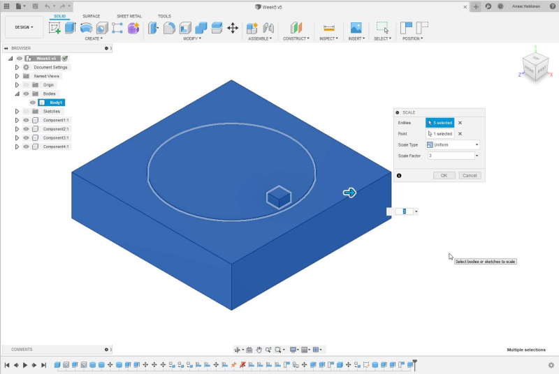
I started operation by scaling whole structure up by 3. This made the base 60mm x 60mm and height 12mm.
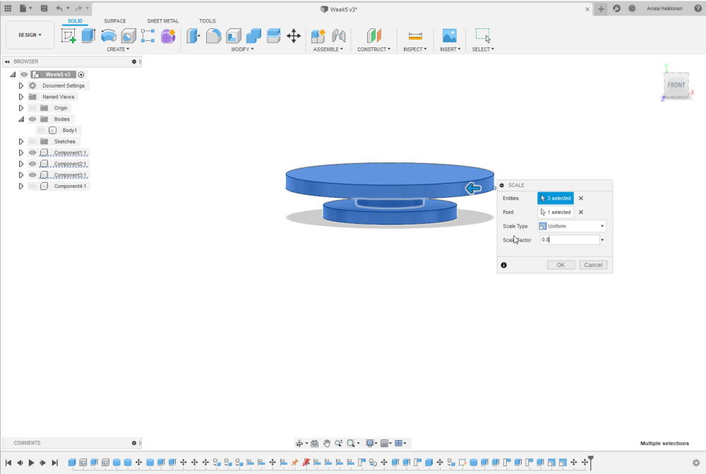
Fastest way to make gaps between base and rotating part more loose was to downscale everything else except base. Because center piece was too short after this I had to extrude it a little bit.
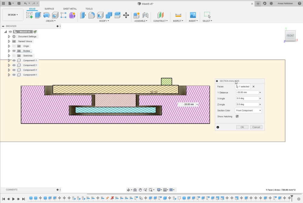
Here is the new section analysis. Now there is a little bit more space, but i am still not sure if it is enough.
Backup plan
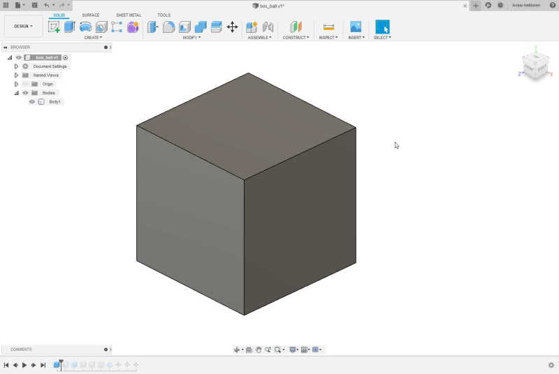
Here is the another design. This was more as a backup if the original design did not work. This was simply box with a ball inside of it. Also holes on the everyside.
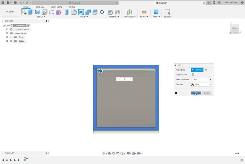
After creating a box I used Hollow tool.
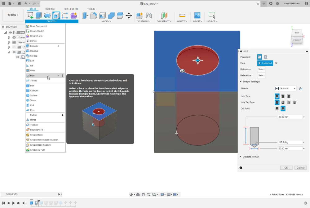
I set up hole tool such a way that it went through both walls at same time. I set diameter 20mm.
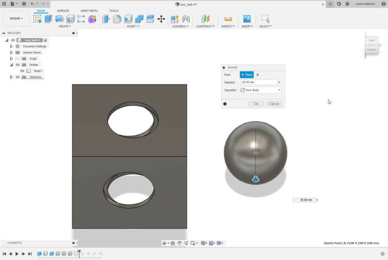
Next I created a ball. For this I set diameter 25mm.
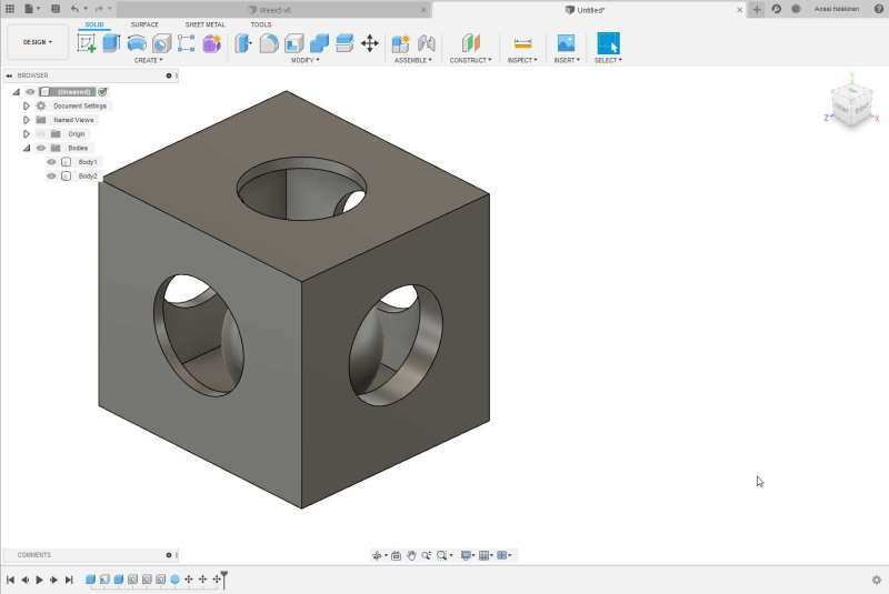
Here is the final design. Probably going to print this one too anyway because I am curious.
Final results
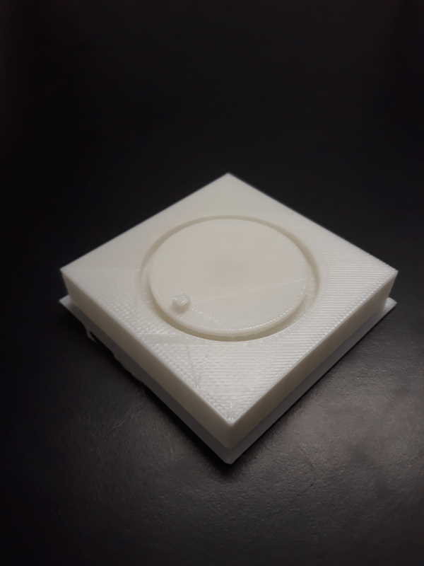
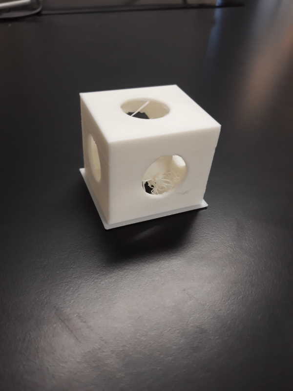
Both of these took over 2 hours to print. I was unsure if it would work this time. I was pretty sure that one with rotating bed would fail again and the simple one would be successful. I spoke with local instructor about the ball and his guess was that it might have moved while printing. After thinking about printing for a while I suddenly remembered that ball was out of position at later part of the printing.
I found out the problem while uploading files into my repository. I should have rotated it in printing software just like I did with the other model. Because of this ball was placed wrongly inside the box and that is the reason it failed.
Platform was stuck so I used chisel to lift upper layer. This had very little effect since problem seemed to be at the middle of object. Next I tried to rotate platform by pushing small handle at top of it. By doing this it started to move a little bit. After this I used edge of table to do the same trick and it started rotating.
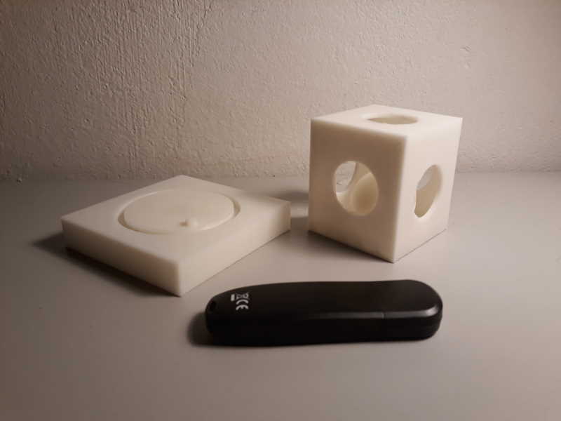
Here are the final products. Black memory stick for a scale.
My main design could not be done by subtractively because of the overhang and so much of the object is inside of the another one. I believe my second design could be done by subtractively, but it would be difficult.
3D scan
I used photogrammetry for this task. I took photos with my phone and used Meshroom to generate 3D model. Meshroom could be run in command line also but I used GUI.
I also ran fast test with MakerBot Digitizer at university. I did not have any interesting object with me at that time though.
Setup and Meshroom
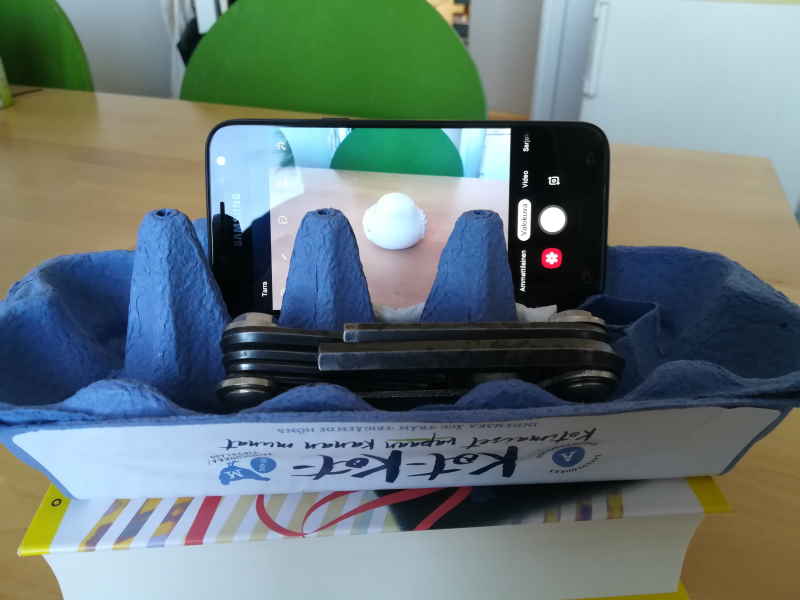
Since I don't have a stand for my phone I had to improvise a little bit. To take photos from higher position I added more books.
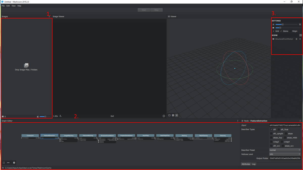
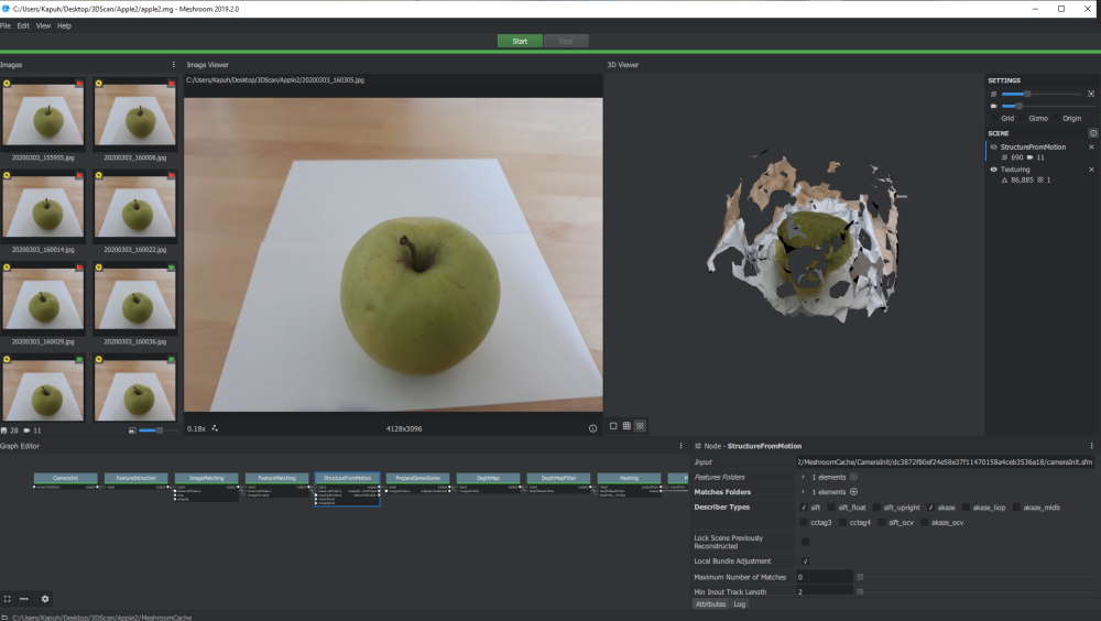
This is GUI of the Meshroom.
- Drag pictures here which you want to be included in generating the model.
- Here are the parts of the process. By clicking one of the boxes you can set different settings on the right corner. You can also make changes into process by linking parts differently , but I did not test those.
- Here you can change what is shown in 3D viewer such as cameras, origin etc.
First attempt
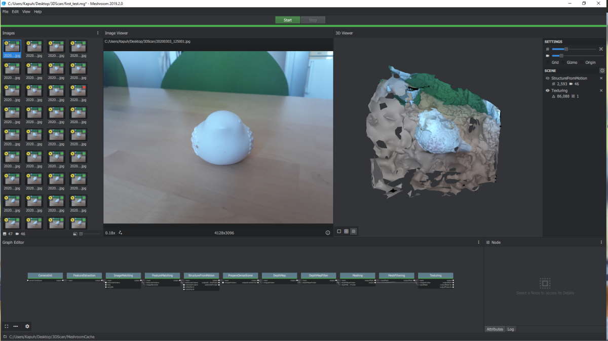
This was my first try. I rotated the statue between the shots. Result was not great since it looks like it's only from one point of view. Pictures that have small red icon on top-right corner were not included in the process.
Second attempt
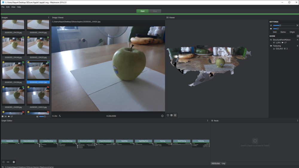
I changed the object because I was not sure what really was the issue at this point. I also added some white paper under the object to test how it would effect. This time result was at least better since it draw nearly whole object. This time object stayed in one position and camera was moving around it. In this one background amazed me, but it was probably because of the lower position of camera.
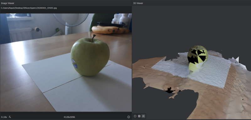
Here is same model from another perspective.
Third attempt
I decided to move position of camera a little bit higher this time so the angle would not be so wide. This had poor results.
Fourth and final attempt
For this attempt I took much more pictures compared to all previous ones. Pictures were taken from 3 different heights and one from above. This time object was still and camera moving around. After checking few forums to understand why quality was not that great I got few tips.
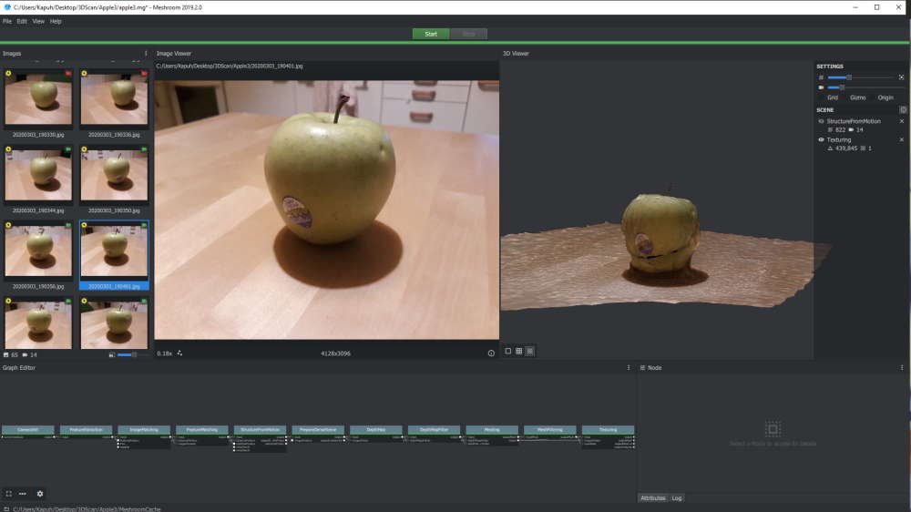
This time I tried to run with Akaze set as DescriberType in FeatureExtraction, FeatureMatching and StructureFromMotion. This had impact on time and it took longer this time to generate. Quality improved compared to last one when object from every perspective. But it was still kinda lackluster.
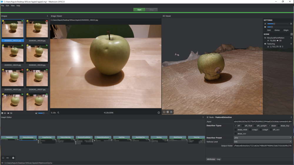
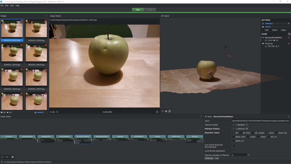
For this one I changed DescriberPreset to Ultra in FeatureExtraction. This really pumped up the quality, but it took also 2 hours to generate from my main PC. This time quality was same from every side of the object.
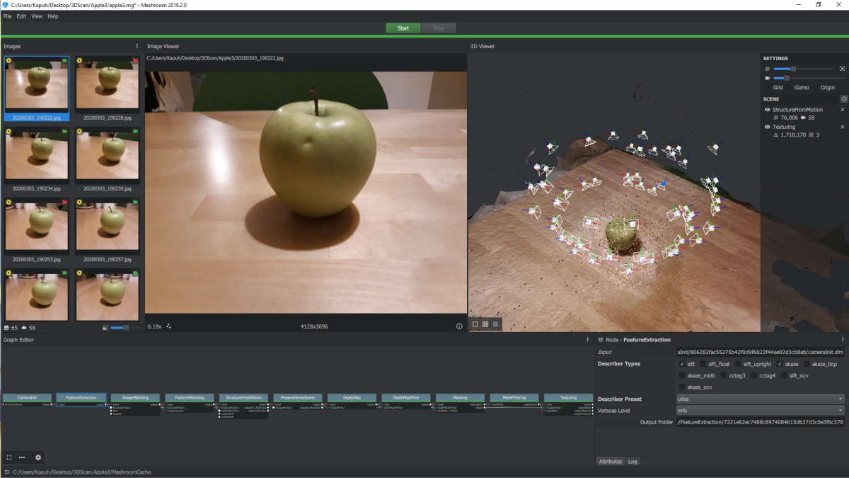
Setting DescriberPreset to Ultra had great impact to amount of angles. Even with this result is still kinda dissapointing at lower half of the object.
This might be because Meshroom did not accept some of the pictures taken. When looking at the angles shown in picture above you can see how most of the angles are pretty high. I am not sure what caused this, but maybe pictures from lower position were not focused correctly or something similar.
Also the lighting of the scene was bad which had negative effect on the result. Especially since in some angles there were shadows laid by the apple. Maybe a platform under the apple would have helped Meshroom to detect which parts to scan.
Meshmixer
Scan result was pretty rough and decided to check if I could fix it a little bit with Autodesk Meshmixer.
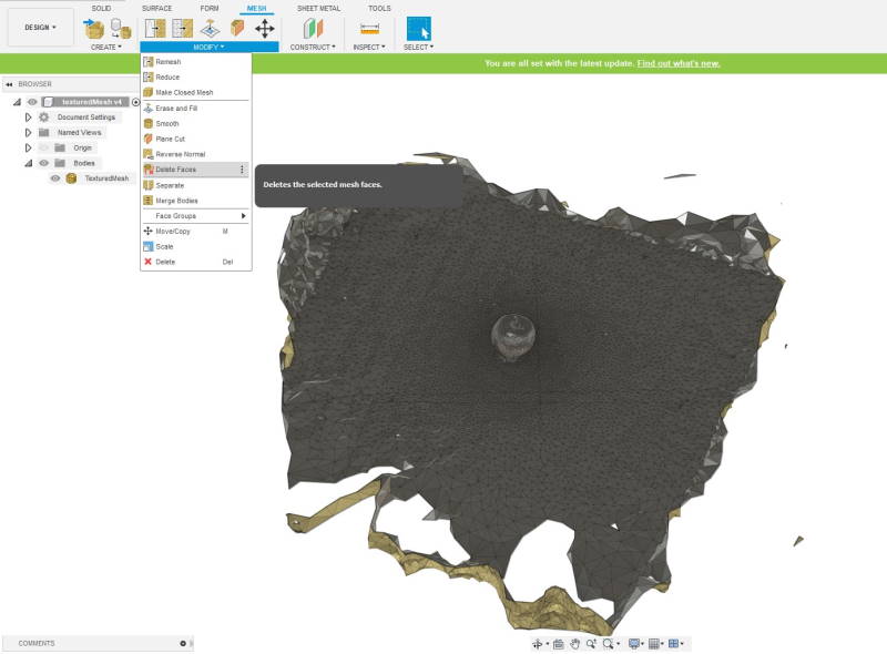
First I wanted to get rid of extra material. This could have been done in Meshmixer as well, but did it on Fusion. There's a tool for this on Fusion and it's called Delete Faces. It can be accessed from Mesh -> Modify -> Delete Faces. Next choose faces you want to be deleted and press Ok.
Here is the result. Just in case left some extra. At this point I exported file in stl-format for the Meshmixer.
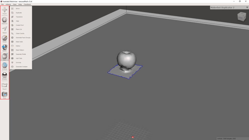
This is Meshmixer. On the left side there's navigation-bar for tools. First I used import to open .stl-file in it.
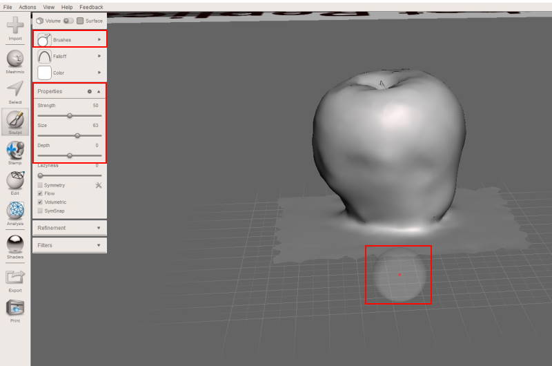
Next I selected Sculpt-tool from the left navigation and used Draw2-brush to fill the bottom part of the apple. Used default settings outside of size, which i changed from 50 to 63.
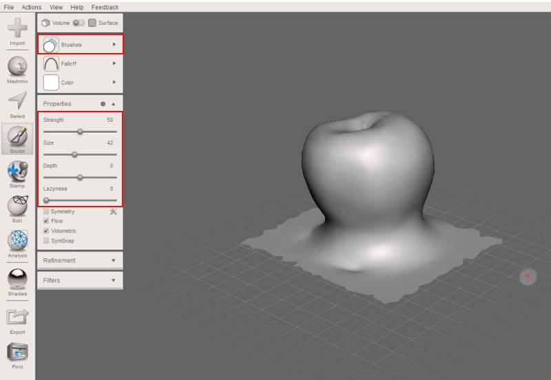
After there was enough material I started to Sculpt it in to a right shape. For this I changed for RobustSmooth-brush.
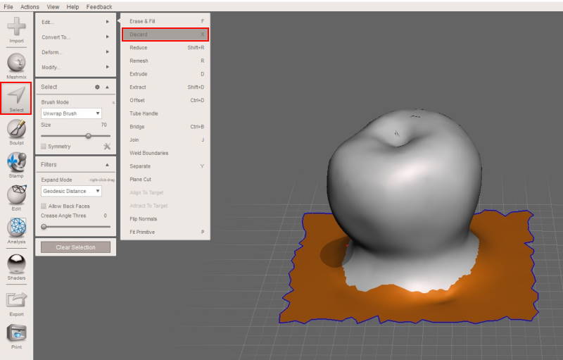
Extra material which I had left on Fusion started to bother me. By using Select-tool I painted the extra faces and used Edit -> Discard (shortcut X) to delete them.
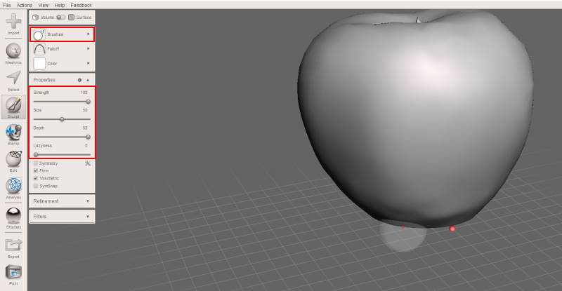
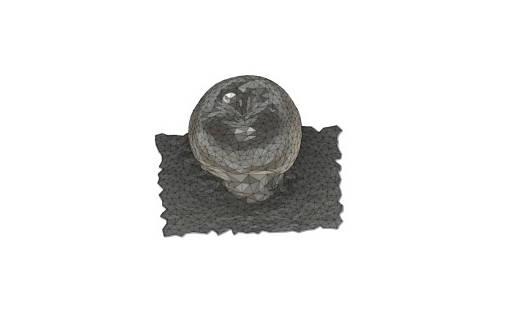
Last part of the process was to push bottom part inside while keeping the shape of apple. This time used ShrinkSmooth-brush with Strength 100, Size 50 and Depth 100. When it was nearly done I started to decrease these settings to get smoother result.
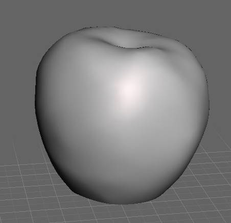
Here is the final result. It improved quite a lot compared to original 3D scan.
Reflection
3D printing was interesting. This time I went shortcut on 3D design by not using parameters and it backfired a little bit when I had to scale whole model. With parameters that would have been faster process.
3D scanning was much harder and time consuming than I had thought. Taking photos with camera was interesting experience but next time I might check other options for this. Meshroom was straightforward to use although I did not tinker settings much. Everytime I ran Meshroom there were pictures that were not included for the process.
Files
Rotating platform (stl)Rotating platform (f3d)
Box with a ball inside (stl)
Box with a ball inside (f3d)
Final_scan (stl)