Final project
Presentation slide
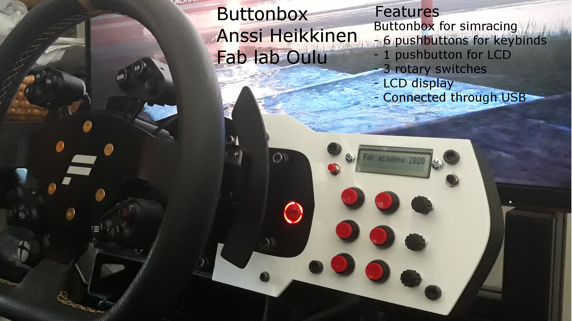
Presentation -file for the final project.
Video of final project
Initial thoughts of final project
I have couple ideas for my final project. Currently I am leaning towards button box for sim racing.
Button box will feature pushbuttons, LCD and some rotary switches. It will be possible to mount on to a wheel base. It would be used by connecting it to PC by usb. Push buttons works as input device so those would be easy to assign from game or program. There could also be software to control them, but not sure would it give any value to it with current using purpose.
It's target audience would mainly be sim racers because of the case design. Most of the commercial racing wheels for wheel bases have very limited amount of buttons and switches to work with. On the other hand most of the racing games have a large amount of essential functions which require a assigned button. Purpose of the button box is to give more buttons to work with. For example GT3 cars have a similar kind of extra buttons for the driver to work with. This kind of button box could be used to control something totally different as well. Although this would probably require another kind of casing.
There is also plenty of commercial and DIY versions. One commercial button box, DSD Button Box Pack for Fanatec Clubsport Wheel has been the inspiration how to make the mounting. This design allows it to be mounted directly on to the wheel base. For the functions, such as buttons etc most of the commercial and DIY versions are close to each other since all of them are mimicing extra buttons available in real race cars.
On second week I created 3d version of buttonbox. Design is still pretty rough and simple at this point.
Have not been actively updating this part of site lately. On week 10 I planned more closely what the button box will be. I am still kinda changing plans day by day and going to keep this page up to date.
List of materials
Here is the list of material for this project.
| Name | Quantity | Source | Cost / item (Eur) | Total cost (Eur) |
| ATmega32U4 | 1 | Fab lab Oulu | 1.85 | 1.85 |
| Pushbutton | 8 | Local supplier | 1.20 | 9.60 |
| Potentiometer 10K | 3 | Fab lab Oulu | 1.01 | 3.03 |
| LCD | 1 | Fab lab Oulu | 4.99 | 4.99 |
| USB Mini B port | 1 | Fab lab Oulu | 1.10 | 1.10 |
| USB A - Mini b cable | 1 | Local supplier | 3.80 | 3.80 |
| FR-1 board | 1 | Fab lab Oulu | 1.22 | 1.22 |
| Led red | 1 | Fab lab Oulu | 0.10 | 0.10 |
| Resistor 0 ohm | 3 | Fab lab Oulu | 0.03 | 0.03 |
| Resistor 10 ohm | 4 | Fab lab Oulu | 0.04 | 0.04 |
| Resistor 220 ohm | 1 | Fab lab Oulu | 0.01 | 0.01 |
| Resistor 10k ohm | 9 | Fab lab Oulu | 0.09 | 0.09 |
| Resonator | 1 | Fab lab Oulu | 0.43 | 0.43 |
| Capacitor 1uF | 2 | Fab lab Oulu | 0.07 | 0.14 |
| Capacitor 100n | 1 | Fab lab Oulu | 0.05 | 0.05 |
| Connector 3 | 3 | Fab lab Oulu | 0.27 | 0.81 |
| Connector 2x2 | 1 | Fab lab Oulu | 0.66 | 0.66 |
| Connector 3x2 | 3 | Fab lab Oulu | 0.60 | 1.80 |
| Connector 5x2 | 1 | Fab lab Oulu | 0.89 | 0.89 |
| PLA, case and button caps | 110.4 + 2.4 gram | Fab lab BusinessAsema | 4.54 | 4.54 |
| Acrylic, lid | 20cm x 15cm | Fab lab BusinessAsema | 1.52 | 1.52 |
Total cost of the used materials is 36.7 euros.
3D - Case
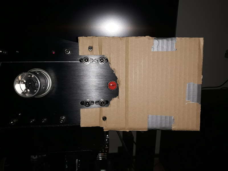
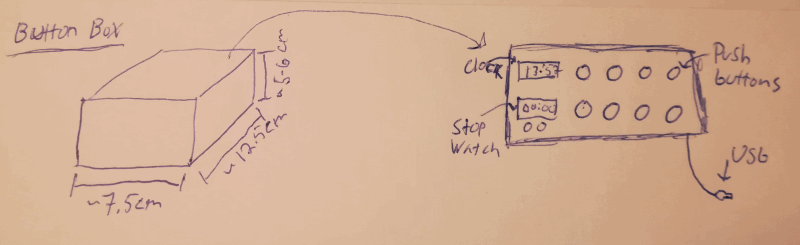
To get better understanding of the size of case and lid I made proto from a cardboard. Also tested the screws on the wheel base to make sure if those are useable. Size of the prototype is 155x130x60mm. Lid has U-shape on the left side for the mounting points on the wheel base. This will probably be hardest part on the casing since it has to be riggid enough to hold the buttonbox.
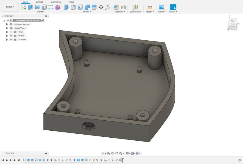
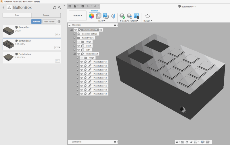
With better vision of the size I started to make a 3D model for it. I got an idea to make it fit more with the style of the wheel base. Size of the case is 120x120x40mm. There are 8 cylinders in total which will be used to attach PCB and lid to the case. Ones for the PCB have slot for a M2 screw and M6 is used for the lid.
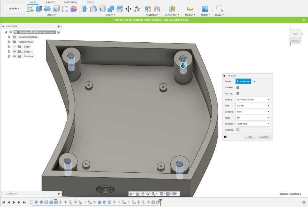
Everything else what I have done for this is similar which have been documented on week 2, week 5, week 7 and week 15 excpet the threads. After you create a hole with Tapped-setting enabled, you have to use Thread which can be found under the Create-menu. Modeled option under the Thread will make physical threads instead of only visual ones.
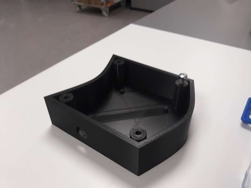
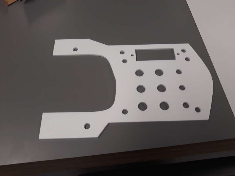
Here is the case after 3D printing. Also checked the threads with a screw.
3D - Button caps
I made button caps for potentiometers with 3D printer. These were designed in the Fusion 360. Mostly used skills learnt on previous weeks as meantioned earlier 3D-section.
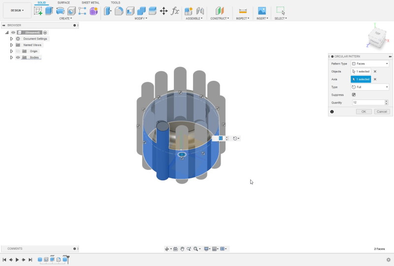
After making a cylinder with a hole and curved top, I wanted to make slots around it. This was fastest to do with Circular Pattern-tool under Create-drowndown menu.
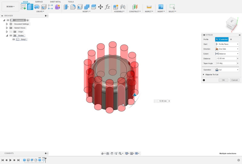
Extruded all the pillars made with the Circular Pattern.
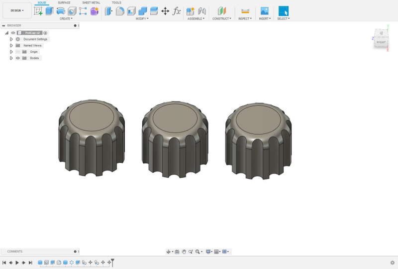
Here is the result after extruded. Copy-pasted couple more of these because I need 3 of them.
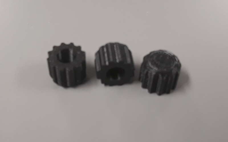
Result after 3D printing.
2D - Lid
Lid will be made from acrylic by using laser cutter. My plan is to take the shape of the case and the positions of holes from a sketch on the Fusion 360 as .dxf and modify it on Inkscape for the cutting. I have documented basics of the Inkscape on the week 2. I like more to work with the Fusion when I have to measure exact distances between objects.
I made multiple test versions of the lid by using cardboard to have exact measures for everything and to have a look how different designs look.
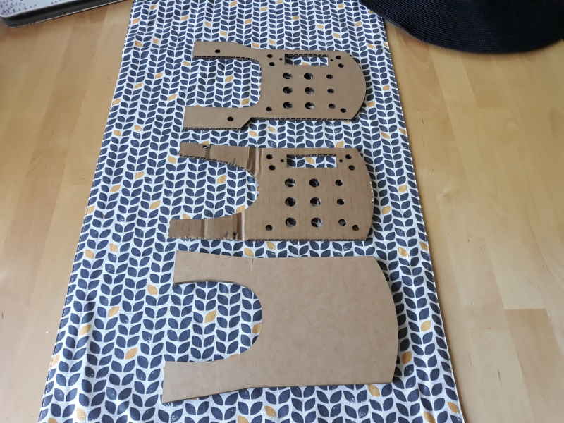
Here is the deveploment of the lid. First version at the bottom and the nearly final version at the top. Because my wheel base was on my rig whole time I wanted to take some prototypes which shape would fit and would look nice.
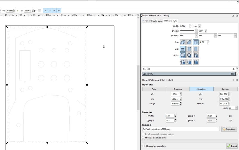
Lid in the Inkscape. Using 0,044mm stroke width since using laser cutter on BusinessAsema.
Final result after cutting it from the acrylic.
Electronics
I have already tested potentiometer and LCD previously. First I was planning to use ATmega328p as my microcontroller, but found out it does not include USB support and would require a FT232 or similar microcontroller to use with it. Because of this I changed microcontroller to an ATmega32U4 which has it. After looking through pin layout and Arduino Pin Mapping I began to make schematic of the board.
Most useful information I have found this far about ATmega32u4, how to program it through usb and help for the schematic of the board.
- Schematic
- Arduino micro schematic
- Programming ATmega32U4
- USB DFU Bootloader Datasheet
- ATmega32u4 programming
- ATmega32u4 programming
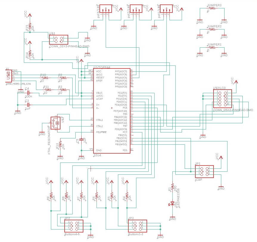
This was first time using ATmega32U4 so I started by checking datasheet for it. Next I Checked Arduino Micro's and Leonardo's schematics first to get some assistance how to connect USB and other important components to the ATmega32U4.
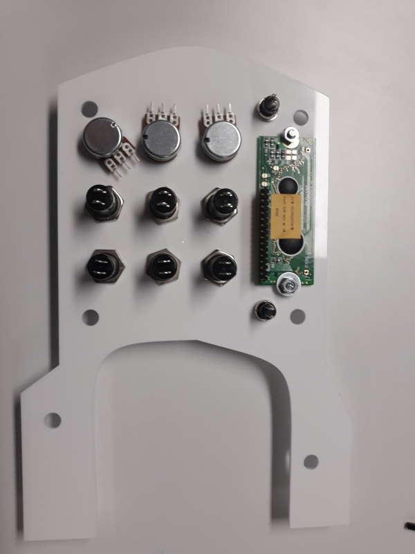
- On the bottom I have connectors for the main pushbuttons.
- On the right side are 10-pin connector for the LCD and 6-pin connector for the SPI which is used to burn the bootloader.
- On the top are 4-pin connector for a pushbutton to control the LCD and reset-button in case required. Also 3x 3-pin connectors for the potentiometers.
- On the left side are the USB, resonator and some required capacitors.
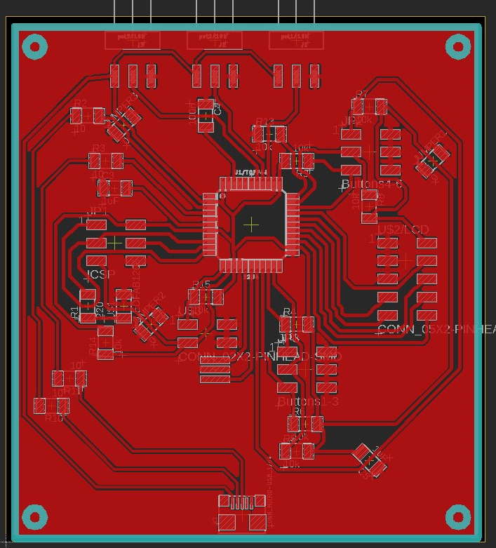
Here is the board after setting up lines. Had to use low clearance options to get rid of errors on pads of usb and ATmega32U4. Because of this 2 out 3 jumpers became useless.
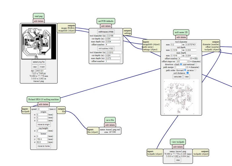
Settings for traces on the Mods.
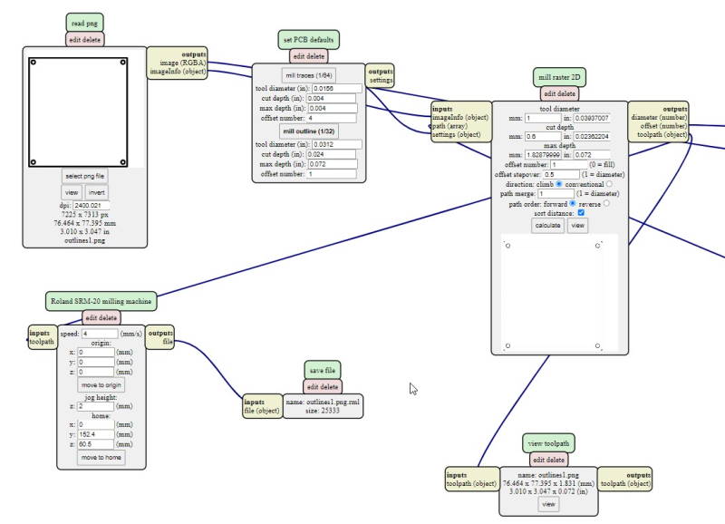
Settings for outlines on the Mods.
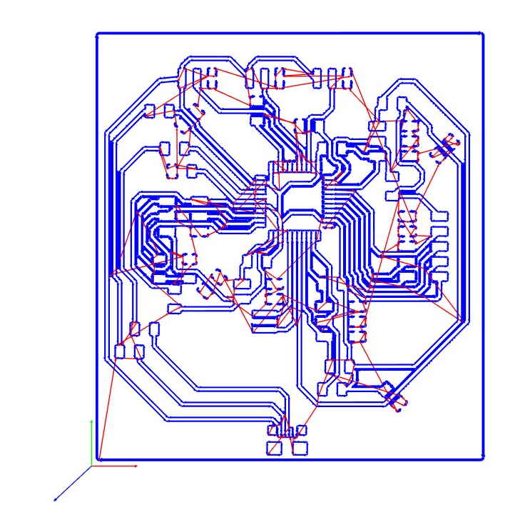
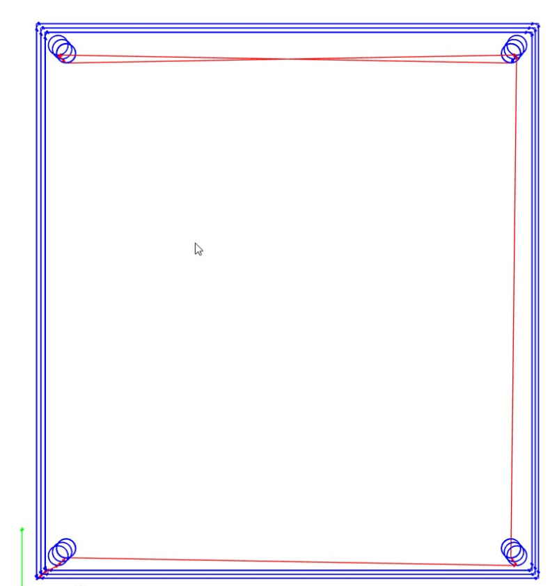
View of toolpaths.
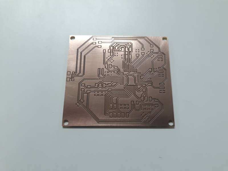
Used SRM-20 to mill the board. This was first time I used our machine at BusinessAsema, but the setup is nearly identical to university.
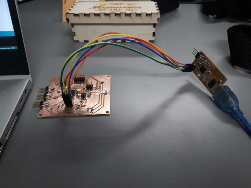
Burning the bootloader. After this the board can be programmed through USB which is extremly useful.
Programming
My concern has been how to make the button box noticed by PC as a controller instead of a keyboard. After going through multiple forum posts and guides I found few interesting to look deeper in to.
- Arduino Joystick by Ingeimaks Ingeimaks
- Arduino game controller using Arduino PRO MICRO by UTSOURCE
- Arduino Joystick Library
- Jakkul's blogpost about Sim racing and game controllers
Local instructor Ivan told about a Map -Arduino library that could also be useful to control potentiometers. Although I did not use it in the end.
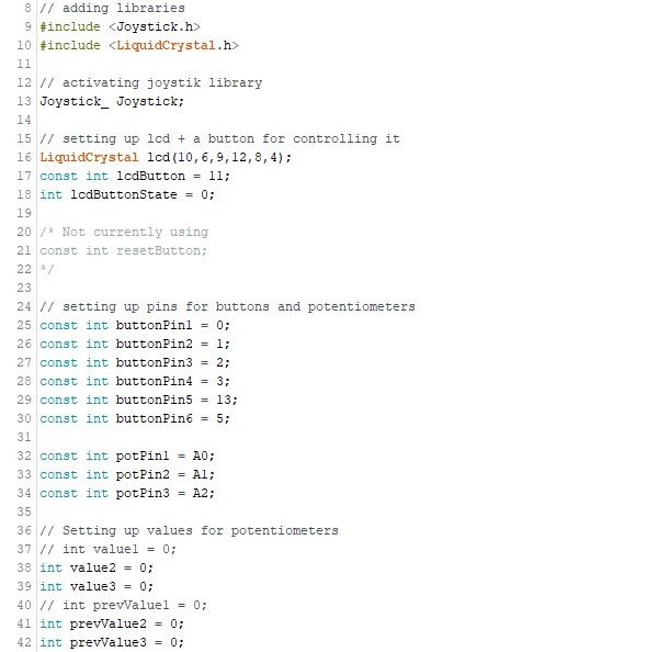
Software is built around two libraries, LiquidCrystal and Joystick. I have explained how LiquidCrystal-library works on week 11 so not going to explain it here. This was my first time using Joystick-library and it worked perfectly for this project. After including it, I had to create the Joystick. With these it is possible to use it later inside the loop(). Reset-button was included just in case if I would need in order to program the ATmega32U4, but it was not necessary. I left it inside a comment if required on a later date.
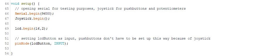
Setup() includes mostly code required for the LCD. Also setting up Serial and Joystick.
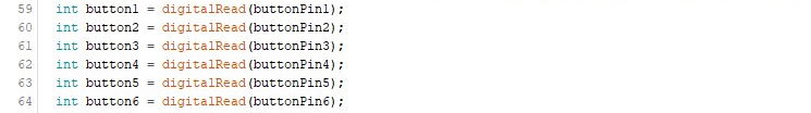
Setting up all the buttons and pin to read for each.
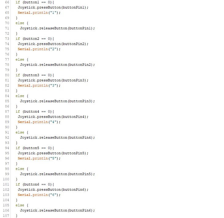
Next I made if-sentence for each of the buttons to check when they are pressed. When button is pressed it activates the Joystick.pressButton and prints the number of the button through serial for testing purposes. Joystick.releaseButton is active when the button is not being pressed.
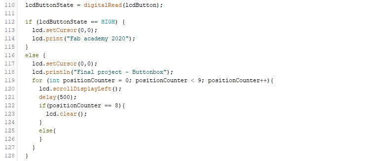
Tested how to scroll a text from side to side through LCD. There is a button which is for controlling the LCD. Pressing the button activates the else-section of the first if-sentence. A new text is printed in LCD and it will begin to scroll text one space to the left once in 500ms. When it has repeated this for nine times the LCD will be cleared and the original text is visible.
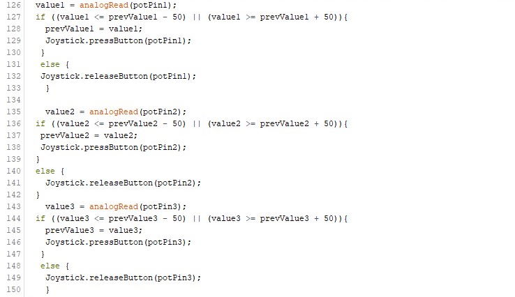
This part includes code for the potentiometers. It works close to same way as the buttons except that it only activates when the digital value of potentiometer is 50 under or over the previous value.
Assemble
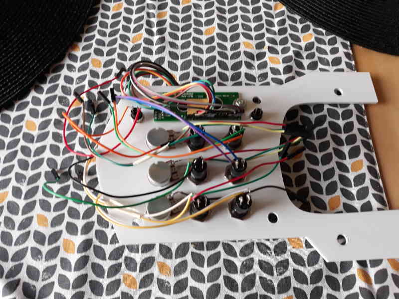
Backside of the lid.
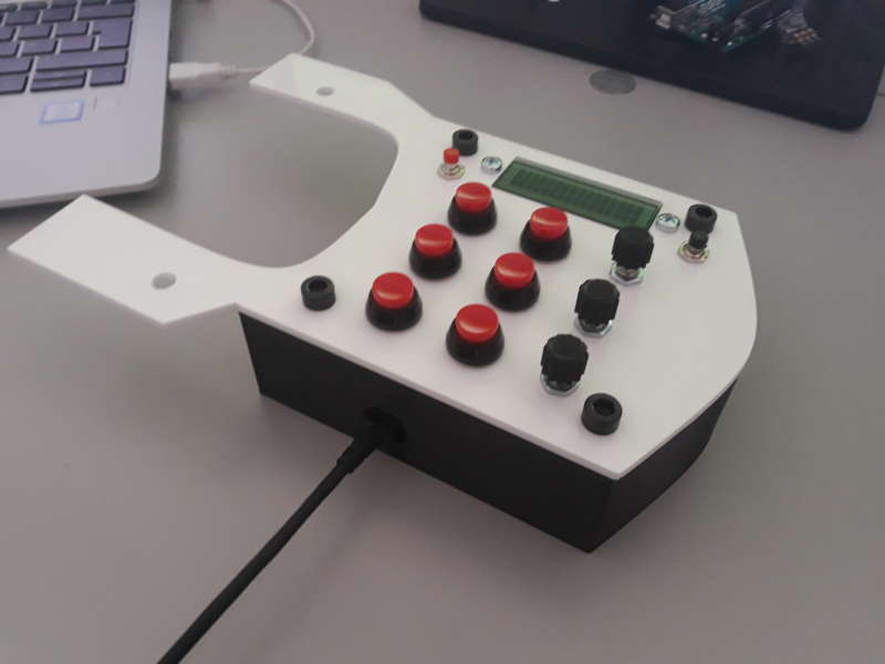
Buttonbox assembled. I kinda like the color combination, but will use black on the lid on the future.
Short video clip showing how the LCD works.
Short video clip of the Buttonbox in action.
License

This work is licensed under a Creative Commons Attribution 4.0 International License.
Software is licenced under MIT license.
Thoughts after assembling
I am satisfied with the fact that it actually works and I was able to assemble it. Still there is plenty of things I am going to change for next version. Starting in the order of the documentation so the case. Case is fine otherwise than that M2 screws for PCB were overkill, should have used M3-M4 instead. Also going to increase the depth of the case probably by 10-20mm. There is lot of cables inside when not using SMD buttons and currently it is so tight that it is difficult to attach the lid. This may also cause damage to wires and connectors or wires to detach. Otherwise the case is fine.
Design of the lid is fine, but the material is not sturdy enough. Have to use more thick material next or maybe 3D print it instead. Might try both options to understand better the difference. Button caps were perfect and not going to change them.
Will change connectors for potentiometers for ones which are pointing up instead of side way. Also might use easier port for usb to solder, usb mini B or B. Also the LCD is currently useless and will drop it off when making next version without restrictions of using all the specific techniques. Outside of these I have not find things to change this far.
Files
buttonbox_original.f3dbuttonbox_original.stl
buttonbox_taller.f3d
buttonbox_taller.stl
lid.svg
lid.f3d
potcap.f3d
potcap.stl
finalproject_schematic.sch
finalproject_board.brd
outlines_finalproject.rml
traces_finalproject.rml
finalproject_program.ino