Week 7: computer-controlled machining
individual assignment:
make (design+mill+assemble) something big
group assignment:
test runout, alignment, speeds, feeds, and toolpaths for your machine
Group assignment
Worked with Achille, Hannu, and Jari in group assignment this week. For group work we used a Caliper and a Tape measure to measure dimensions of a test part between a design and milled object.
Our group's documentation can be found from Hannu's site.
Individual assignment
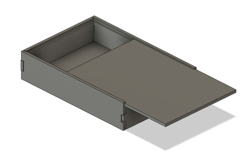
I am going to make a storage box with sliding lid this week. I have a 120cm x 260cm x ~11mm piece of OSB to work with.
Design
I am using Fusion360 once again. I will start by making some parameters and sketches for each unique part. I have explained how to setup and use parameters on week 3.
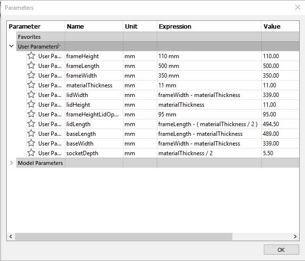
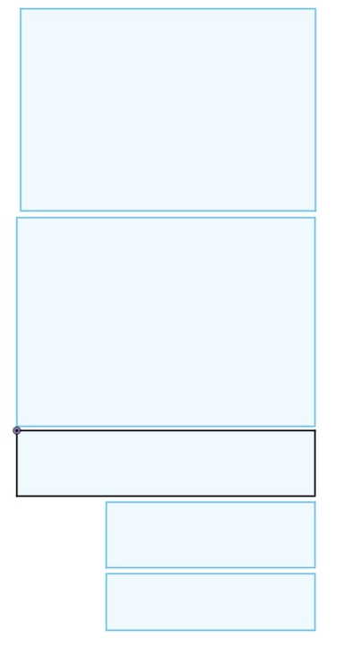
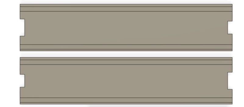
These are the parameters I used. On the right side there are the sketches for the unique parts.
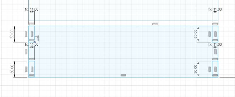
Next I made slots for the sides for each side of the box. With these frame can be connected together. I used Trim-tool to take off the extra lines.
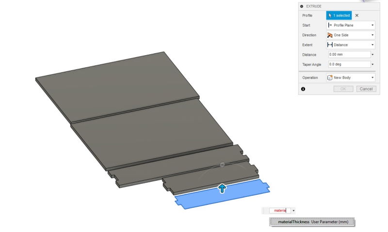
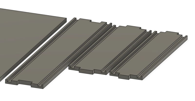
Extruding all of the pieces. Distance set as materialThickness.
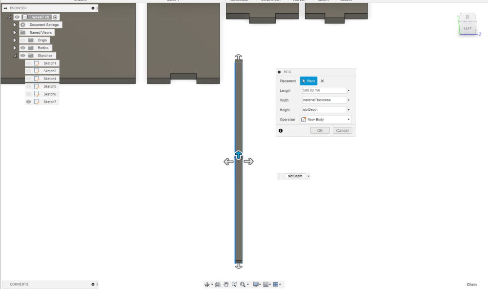
Doing technically same thing as with sketches, but this time with a Box. This will make slots same height as materialThickness and width is set as a slotDepth which equals materialThickness/2.
Placing the pieces where I want to have slots. These are placed on 6mm below of the top and 4mm above of the bottom.
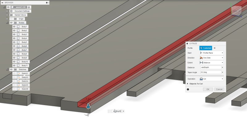
Extruding the slotDepth on each of the piece.
First assembly try which failed miserably. I had not taken into account that I have to mirror the long pieces instead of just copying. Because of this slots did not match.
Mirroring the sides.
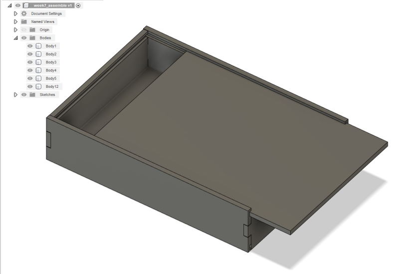
Now it fits perfectly. It is pretty tight, but the thickness of the OSB can vary between 9-11mm and materialThickness is set on 11mm.
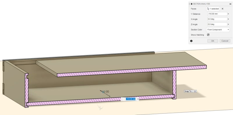
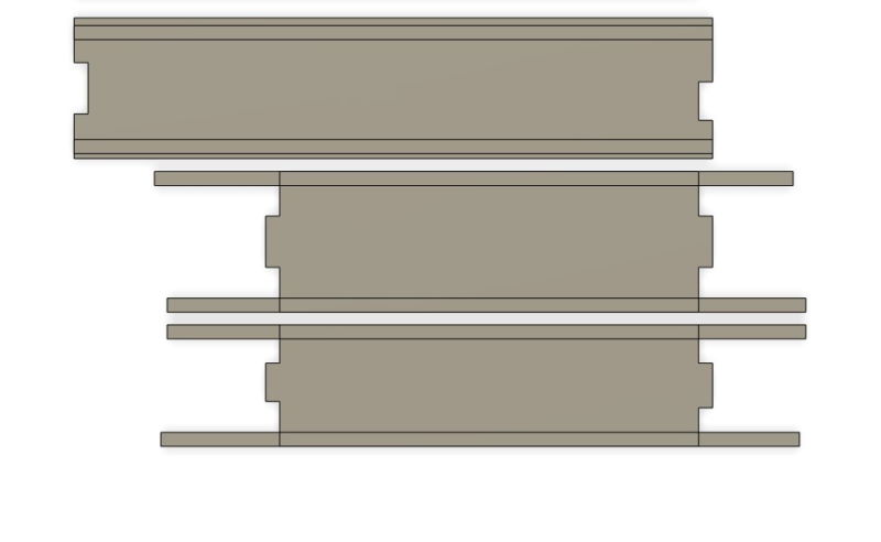
Also checked the box with Section analysis to avoid problems. Didn't notice anything out of ordinary.
Manufacture
To create toolpath for the CNC router I used Manufacture-section in fusion.
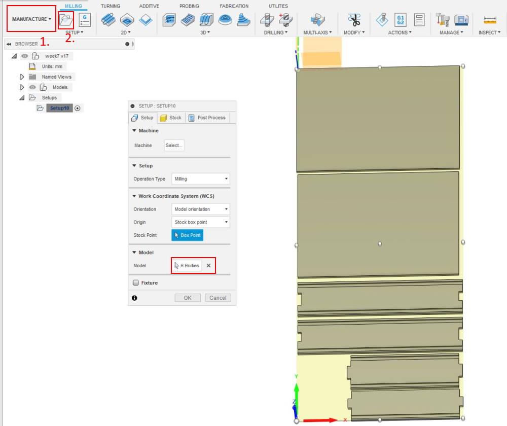
- Open the Manufacture
- Press Setup
First starting by Orientation, Origin and Model. I tried few options under the Orientation, but used Model orientation since it seemed to work fine. Set the Origin manually at the bottom-left corner and selected all the bodies.
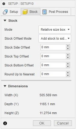
Changed all offsets to 0 and left everything else default.
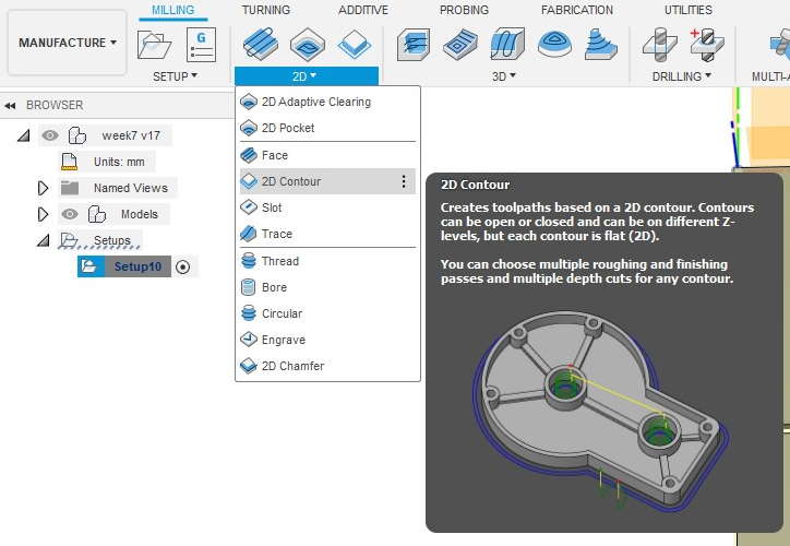
Next open 2D Contour. Used this to create toolpaths for the outlines.
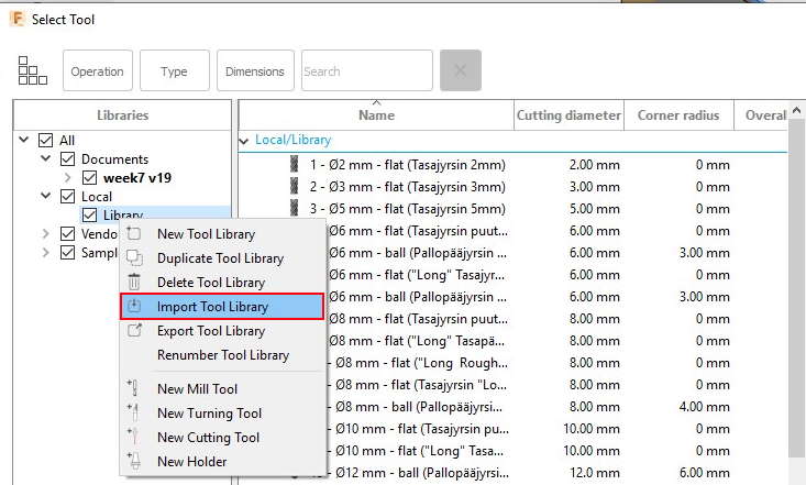
Our lab provides a library of tools to use FABLAB ROUTERI TOOLS 2020-3.hsmlib which had to be imported in to fusion. This can be done while on tool selection page and right-clicking "Library". Then select Import Tool Library and select the chosen file.
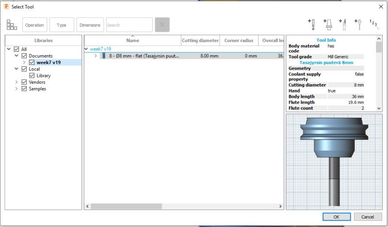
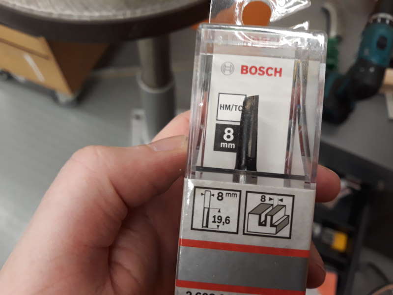
I chose the 8mm flat end mill.
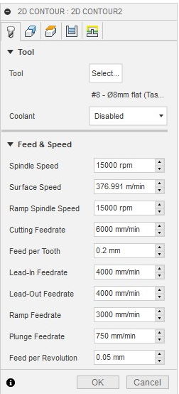
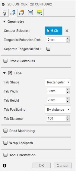
Used mostly default settings. Contour selection was done by clicking the lower line of the each object. Added tabs to avoid the movement when it is cutting.

Used mostly default settings here as well. Changed the Bottom Height to Model bottom.
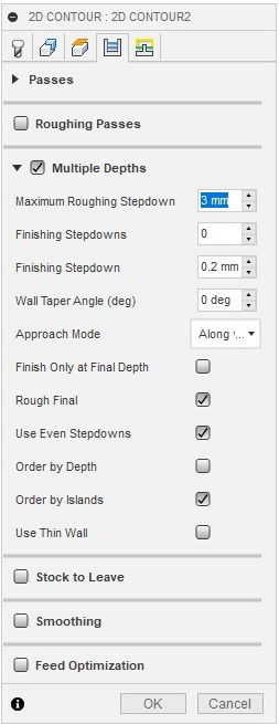
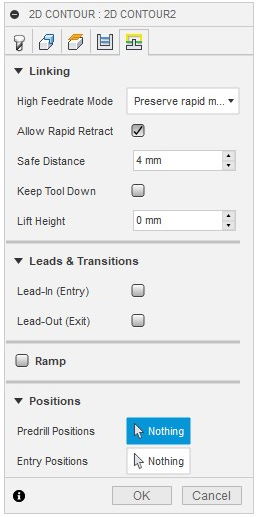
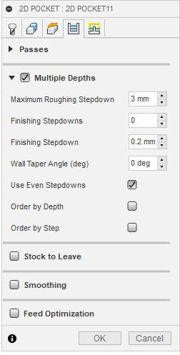
Last set of settings for the 2D Contour. Changed Maximum Roughing Stepdown to 3mm and selected Use Even Stepdowns to avoid extra pressure to end mill. When done press Ok and it will create toolpaths.
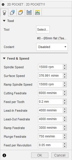
Next I had to do nearly same process for the 2D Pocket. Again selecting the same tool.
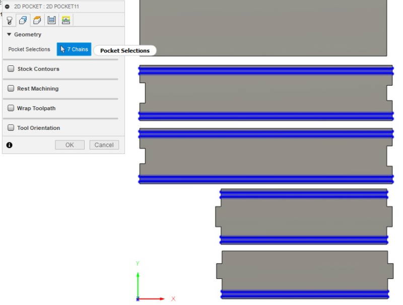
This time only selected the slots.
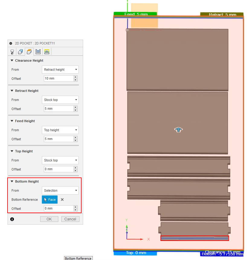
Mostly default settings here as well. Changed the Bottom Height to Selection and selected face from bottom of a slot.
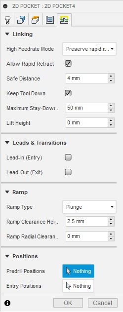
Mostly default settings here too. After asking local instructor Eino to check if everything was okay he mentioned one option I should change from here. The option is Ramp Type and it should be set on Plunge instead of Helix.
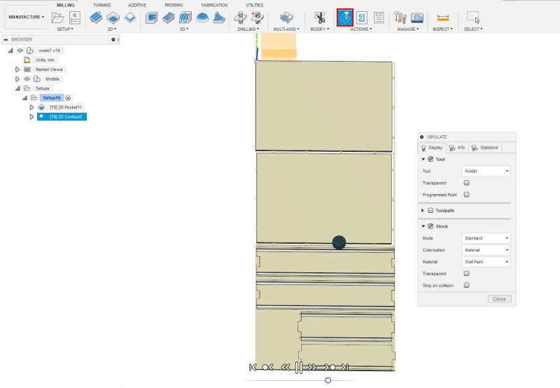
Ran simulation to check if paths were correct.
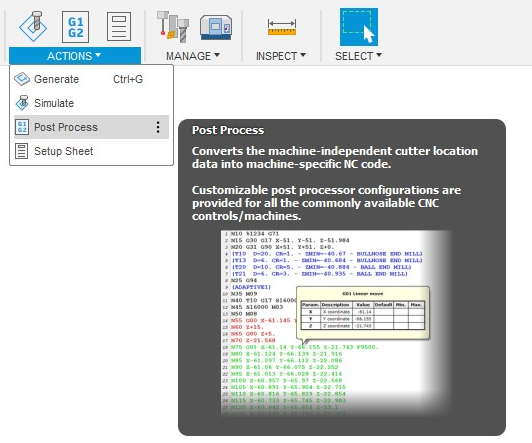
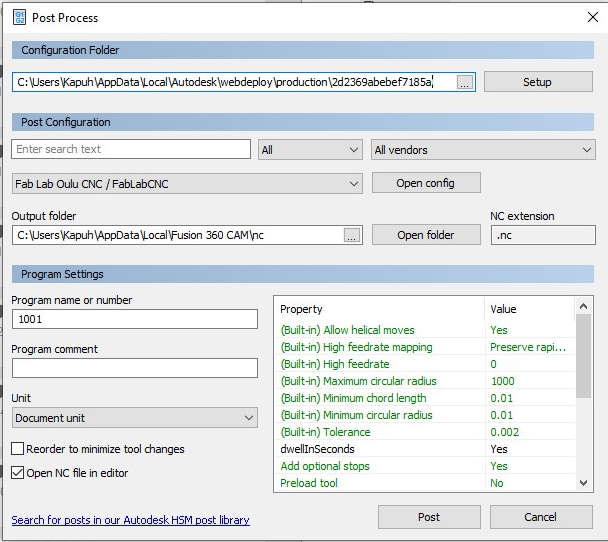
Lastly had to create nc-file for CNC router. This can be done in the Post Process. First I had to put FabLabCNC.cps inside the Configuration Folder. It can accessed by clicking the three dots left on the Setup-button.
Milling
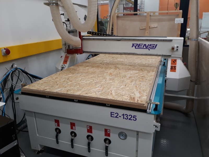
CNC router we have in lab is Rensi E2-1325.
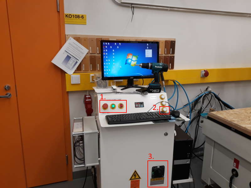
Here is the computer and control center for the machine.
- From left to right: Emergency stop, power On and power Off
- Sawdust extraction switch
- Main power switch

Next it was time to put 6 screws to keep the board fixed during the cutting. These were placed one in each corner and rest on edges close of the middle.
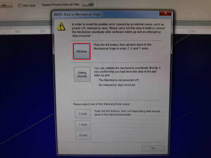
I picked up the right end mill (8mm flat), but before changing it we moved arm closer. To do this we had to open NcStudio and to avoid position errors we set the machine Back to Mechanical Origin in All axes. After this we moved the position of the end mill closer to edge of bed from the NcStudio.
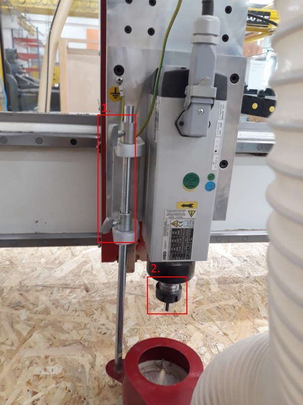
- Loose these two screws and slowly lower the tube
- Loose the nut by using two wrenches and don't allow it to drop to the table
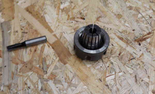
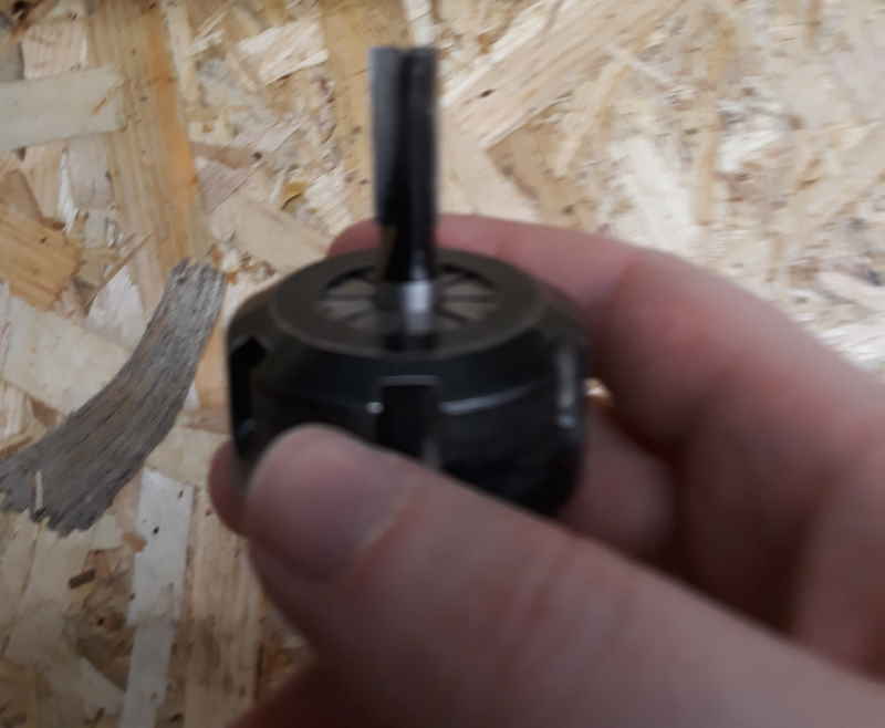
Pull off the previous end mill and insert a new one. Put it back to the socket and tighten it with the wrenches.
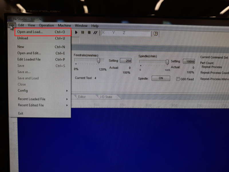
To open the NC-file, press File from top left corner and choose Open and Load.
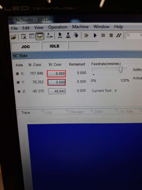
From the right edge of the interface it is possible to move the position of the end mill. When it is at good position (in my case close to left corner of the bed), press the button close to X and Y at top left.
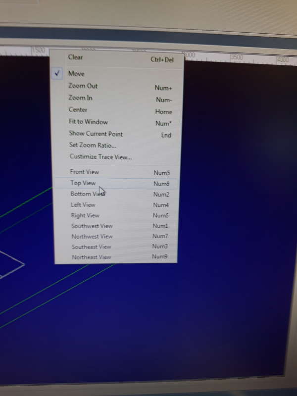
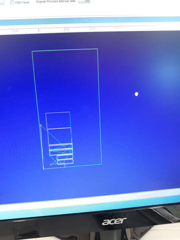
To change the view, right-click on the middle of screen and choose Top view.
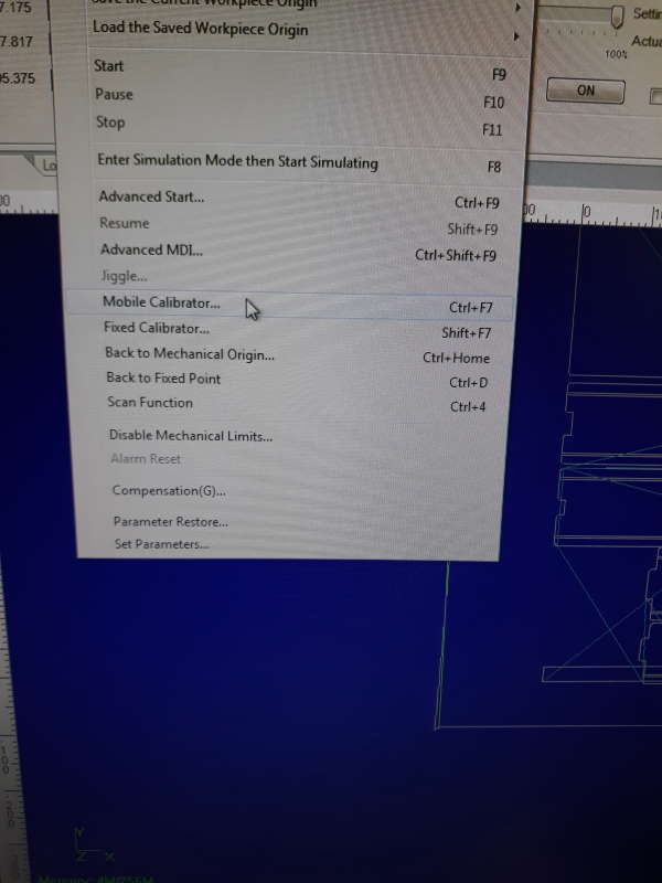
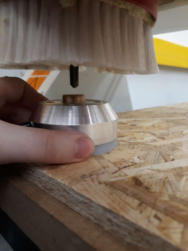
Last thing to do before action is to set Z-origin. This is set with a Mobile Calibrator on this machine. To do this, first press the Mobile calibrator-button. DO NOT PRESS CONTINUE YET, I made this mistake and we had to start from the beginning with the NcStudio. Instead insert the mobile calibrator under the end mill and then press Continue.
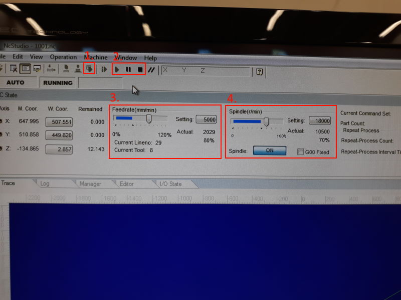
You can run simulation before running it the milling.
- This is simulate
- Here are Play, Pause and Stop
- Feedrate, we lowered it to 80%
- Spindle, first lowered it also to 80%, but it was too high. Lowered it to 70% and ran with it till the end
After setting Feedrate and Spindle, press Play.
Short video of the process.
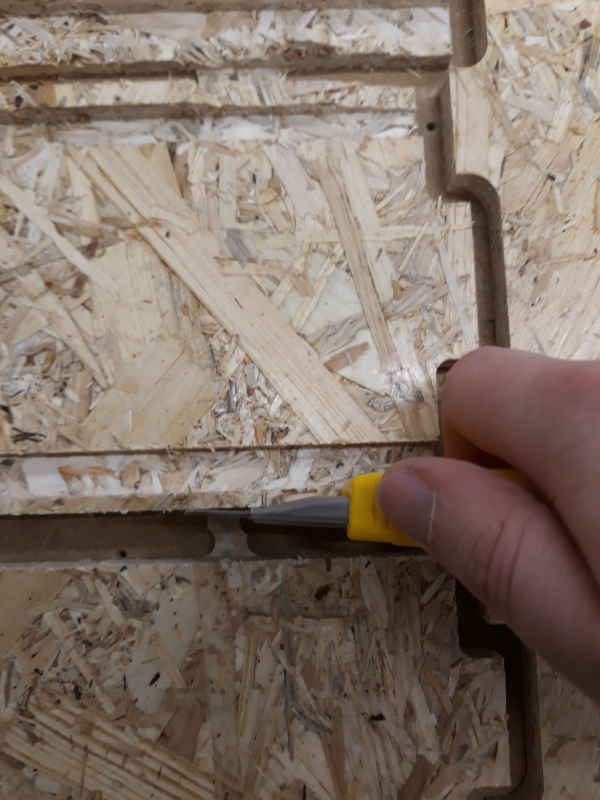
Before assembling I had to cut off tabs. I used sharp knife, in this case stanley knife.
Assemble
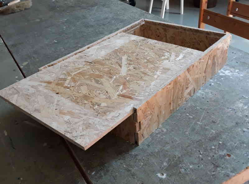
Forgot to take picture when I had all the pieces at the table, but here is the final result. I had to use good amount of sandpaper to make it fit. Material thickness of all the boards were more than 11mm and this made all the slots too small. But in the end all the pieces fit together.
Problems
I made two mistakes with the design.
- Gaps between objects were too small and the whole milling could have gone horribly wrong. I was lucky that tabs kept the pieces together. After milling, local instructor Eino noted that the gaps should have been around 20mm. I had forgotten this.
- Distance between slots and the edge of the piece were too small. Because of this some pieces had been cut off, but in the end it didn't matter that much when assembling it. This was caused by too small gaps and also the material is pretty fragile.
Files
week7_box.f3dweek7_box.stl
week7_box.nc