Week 3: computer-controlled cutting
Week three's assignment was to create construction kit, making something with vinyl cutter and group assignment to characterize the used laser cutter.
Vinyl cutter
Vinyl cutter is computer controlled machine which requires vector images. It can be used to create stickers and logos from vinyl for example.
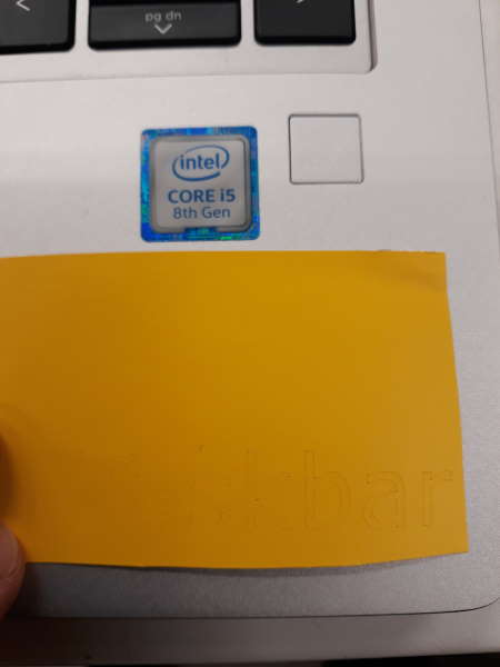
Hardly anyone ever notices that my windows taskbar is at top of my screen instead of bottom when they are trying to show me something. My plan is to make something that would draw attention. There seems to be room for a 10cm x 1,1cm sticker above laptop's screen. My design for this is pretty simple because it is only text "Taskbar" written with color that works with black background.
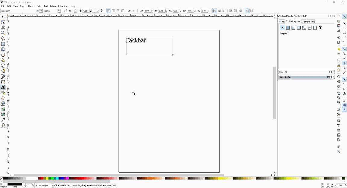
Firstly I used text tool (shortcut F8) to write "Taskbar".
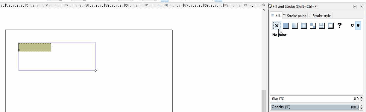
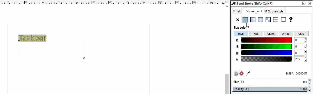
Next setting Fill and stroke for the text (shortcut shift+ctrl+D). Fill needs to be set "No paint" by pressing X-icon and Stroke paint on Flat color.
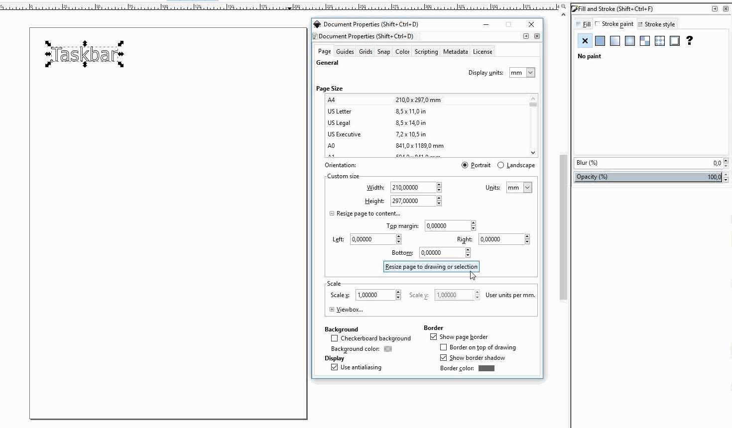
Resizing from Document properties (shortcut ctrl+shift+D).
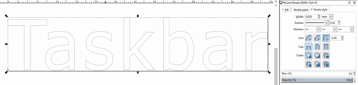
Last thing to do in Inkscape was to make stroke style width 0,02 mm. After this I moved the file with usb stick from my computer to one with vinyl cutter attached to it.
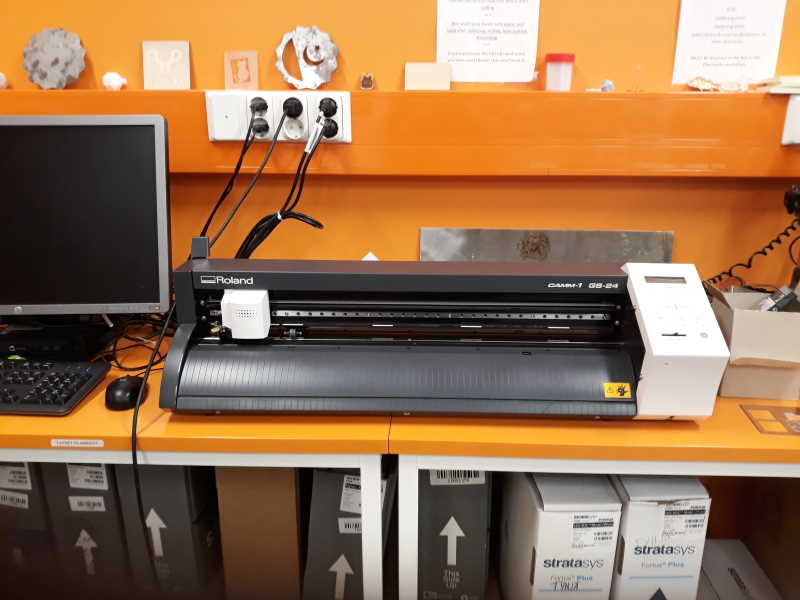
Vinyl cutter in our Fab Lab is Roland CAMM-1 GS24.
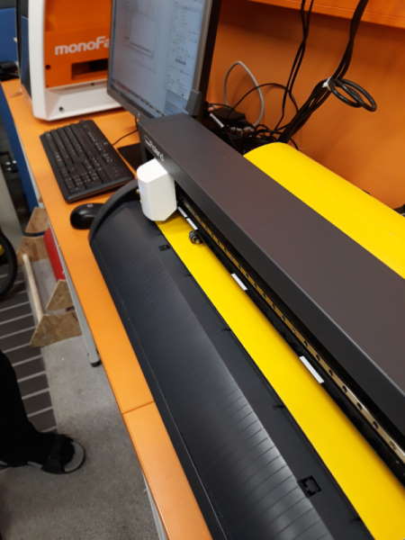
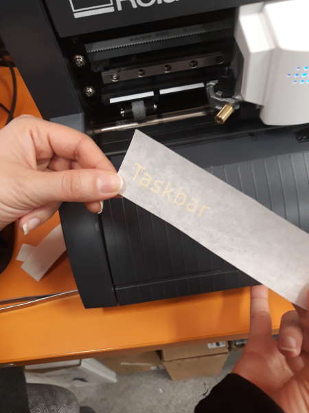
I picked yellow roll from the selection of colors. Edge of vinyl is best to set close to knife to avoid usage of extra material when cutting. Pinch rollers needs to be set at edges of vinyl and on the white indicator lines. After all this piece needs to be attached by pulling the lever in the upper left side of the machine.
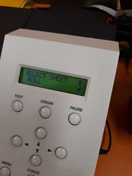
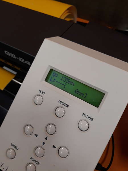
There is 3 sheets to choose from. I used roll. It is not advised to use Piece option unless you have small piece and you need width AND height of the piece. After choosing sheet, machine tests width and shows it on screen. This is useful since there is option in print options to get size from machine.
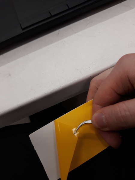
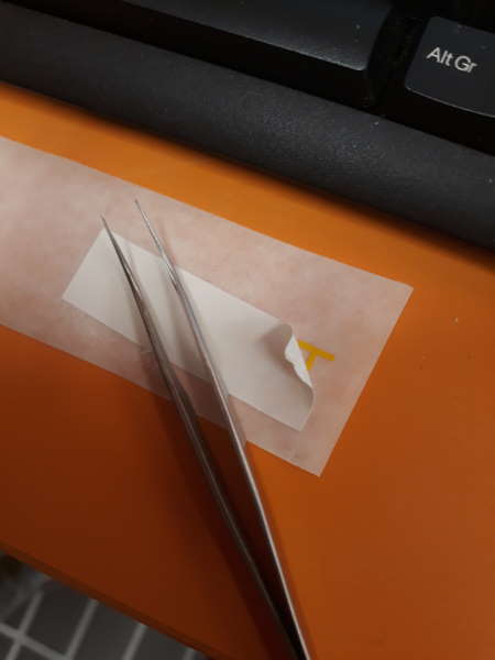
After the cut vinyl was ready was ready it was time to cut piece out of vinyl roll with scissors. After having the piece finaly in my hands it was time to peel of extra material. Small pieces did not come off as easily especially inside parts of a and b.
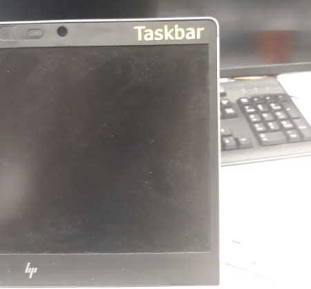
Here is the final product. It sits quite well on the spot and I am happy with it. After I saw other people turning pictures from internet into a sticker I want to make one myself someday!
Parametric designing, construction kit and laser cutter
Parameters are variables which can be assigned to objects. This allows easier changes to be made to a design since only few values have to be changed. My choice of CAD software for parametric design was Fusion 360. I saw also freeCAD in action for parametric designing and it looked pretty good as well. Probably going to give it another go some week! Setting parameters made resizing and fine tuning faster after initial struggle.
My construction kit contains 3 pieces: circle, pillar and filler-piece. After creating these I actually created fourth one, which is square. All of the pieces except filler has slots for press-fit.
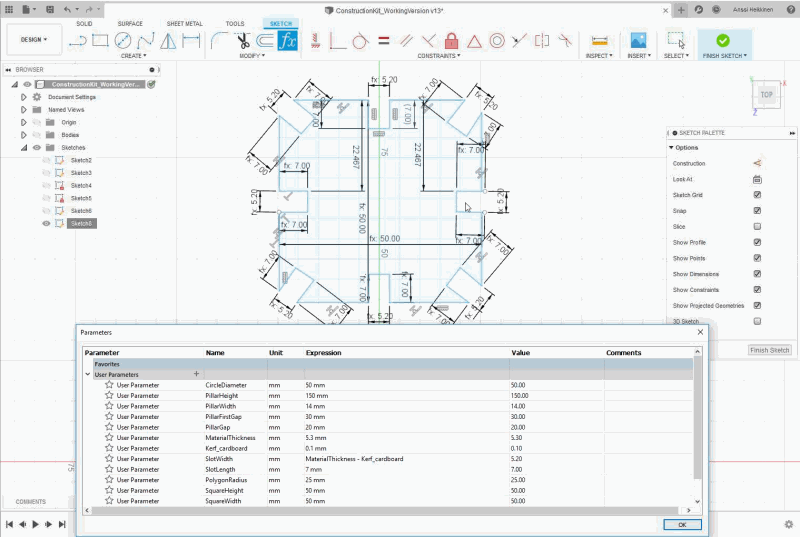
I started by setting couple parameters that I already knew will be used. Parameters can be set by opening Modify-dropdown menu from top and selecting Change Parameters. My naming scheme at this point is unclear so it is easier to take names for parameters from the end.
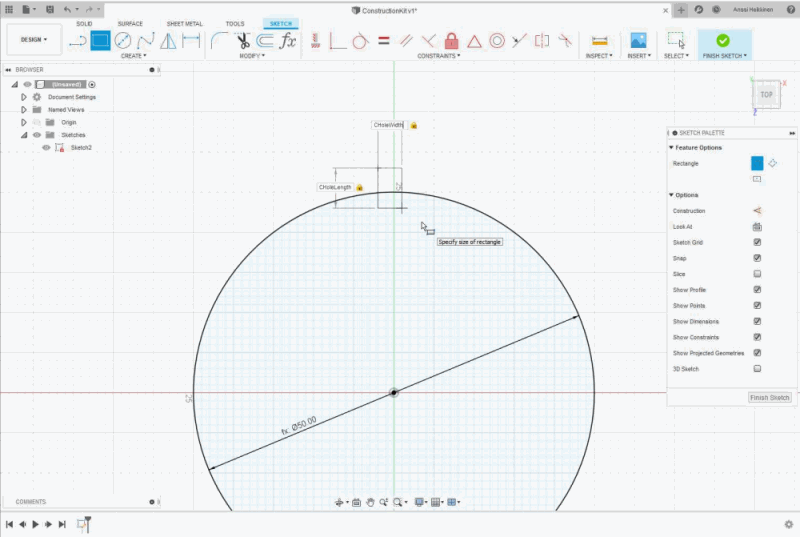
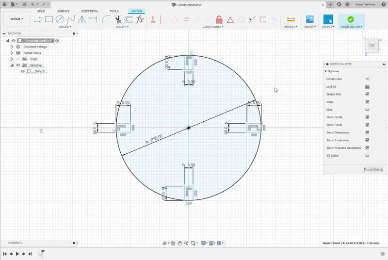
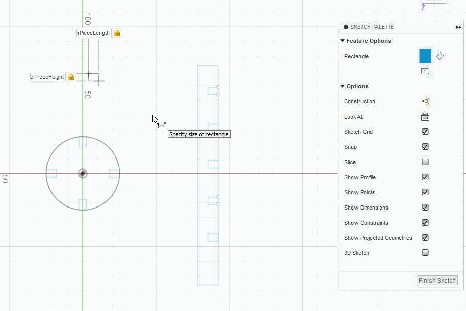
Next I created a circle (shortcut C) and set it's diameter with parameter CircleRadius. I needed slots so i created rectangles (shortcut R) and used CHole-parameters.
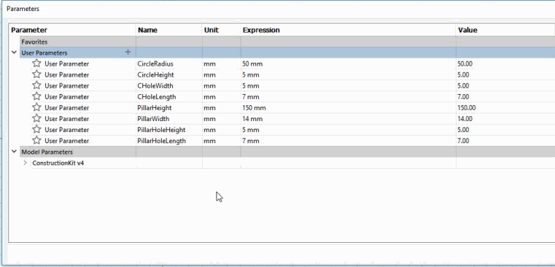
I made parameters for pillars which would keep my initial construction standing. These will have slots which are same length as in circles and height is same as material thickness of circles.
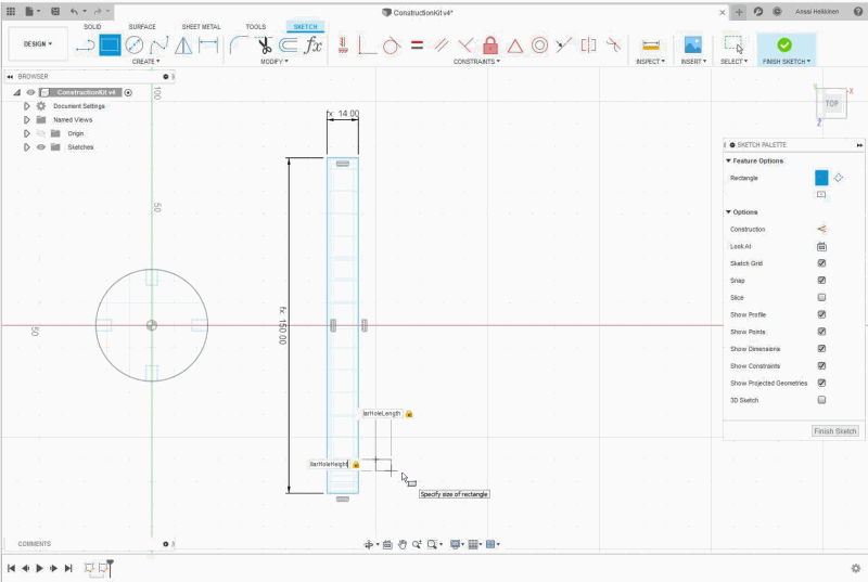
Made slots to a pillar with parameters set previously. At this point I didn't have universal parameters for slots which was a mistake. These were created a little further in the process.
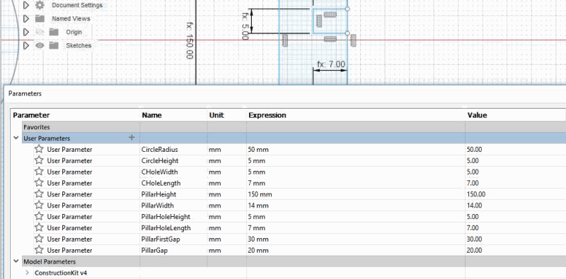
Making adjustments while creating the pillar. I noticed that it would be ideal if there was parameter for gap between slots and gap from bottom to first one. This way it is easy to keep certain distance between slots. Used parameters for this were PillarFirstGap and PillarGap.
Pillar with all parameters set.
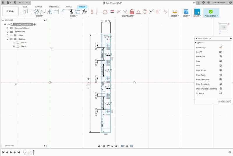
Filler piece for slots which are left empty. This piece was created with rectangle tool (shortcut R) once again. These parameters are changed to SlotLength and SlotWidth later.
When creating circle and rectangle I forgot to trim (shortcut T) lines that are useless. Circle also had different kind of problem but more about that in "Problem with Fusion" -section.
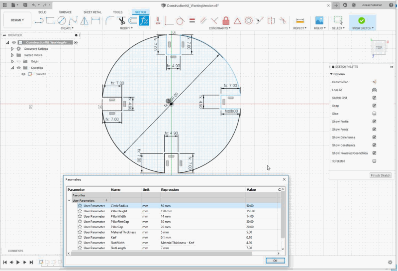
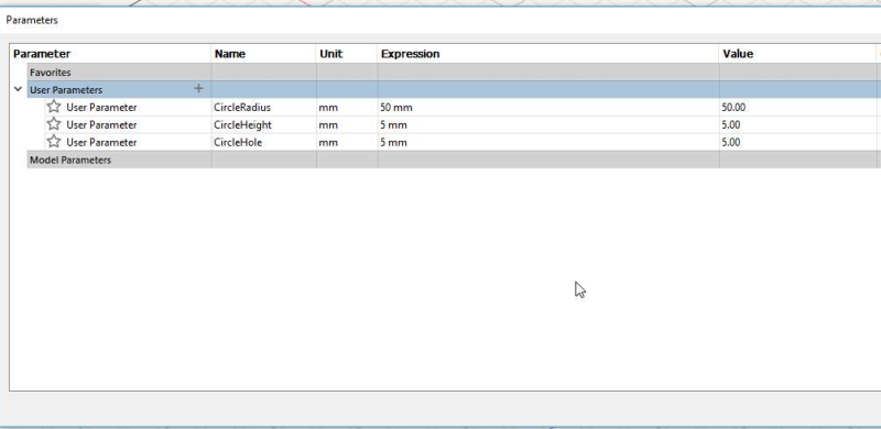
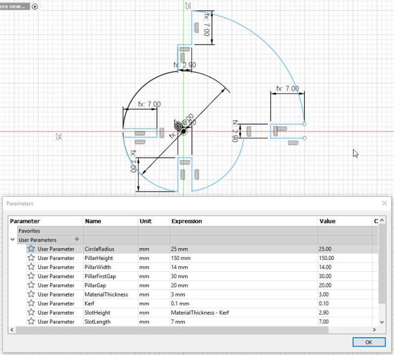
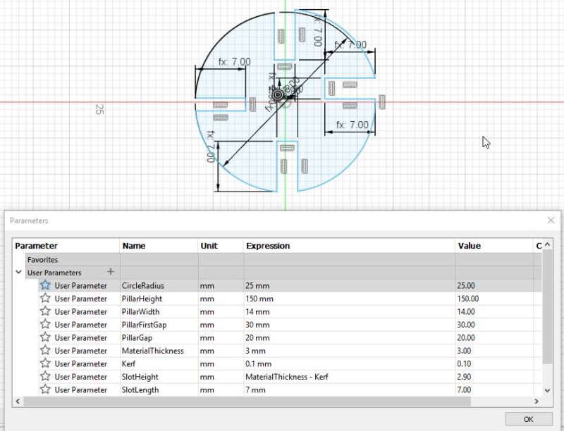
Here are final parameters and design. These went many changes while working with design. I have to keep an eye on my naming scheme in the future because it is confusing. Because slots are inside of the object kerf is calculated by taking kerf off material thickness. If slots were outside I would have had to add amount of kerf to material thickness.
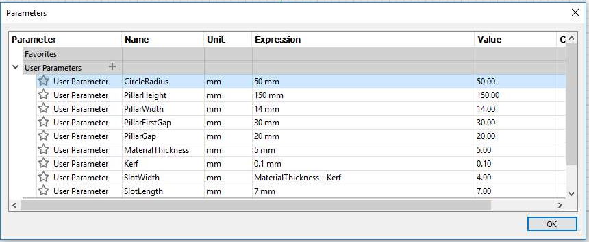
Close up to final parameters presented earlier.
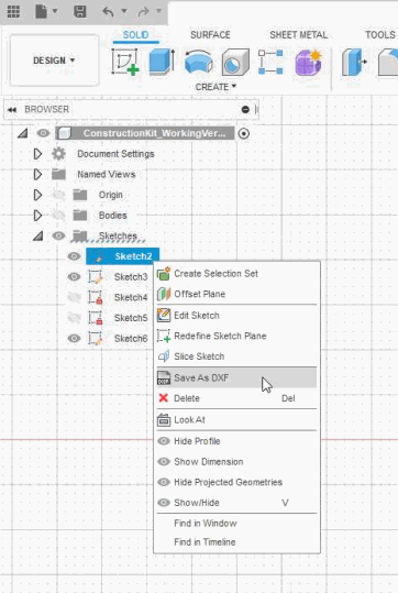
I searched ways to get my files from Fusion 360 to laser cutter and found advice to change sketch to .dxf so I tried it. It worked fine with Inkscape version we have in BusinessAsema Fab Lab.
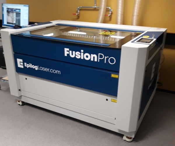
We have EpilogLaser's FusionPro at BusinessAsema. It is little bit different than one in Oulu university. Laser cutter should never be left unsupervised because it might burn whole premises down. Wait for a minute before lifting lid after a cut because there might be harmful gasses.
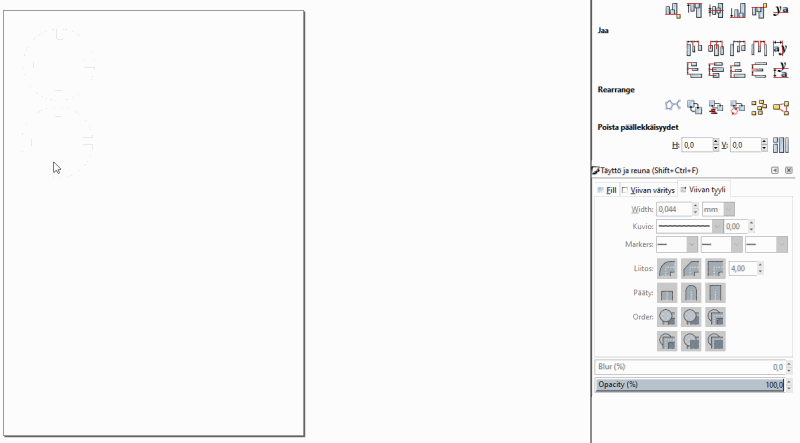
I opened .dxf files with Inkscape and set line stroke line width to 0,044mm. According to Jari, it should be set lower than 0,077mm. At university this needs to be 0,020mm. When line width was set I used shortcut ctrl + P to print.
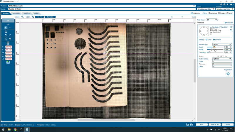
I used preset for 4,5mm cardboard and changed settings after few tests to speed 45%, power 25% and frequency 10%. It is hard to see from this picture but there are 4 purple dot-lines inside on the screen where material can be seen. Object needs to be inside of these. After checking all settings were okay I pressed Print from down right corner.
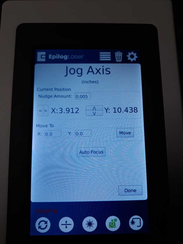
This is UI of the laser cutter. Jog-menu opens when pressing second icon from right at bottom of the screen. This machine has auto-focus, but it can be also set manually. When using auto it is very important to move laser over the material before pressing auto-focus so it won't get stuck on grid. Laser can be moved with joystick which is located below this screen. After setting focus I pressed Done.
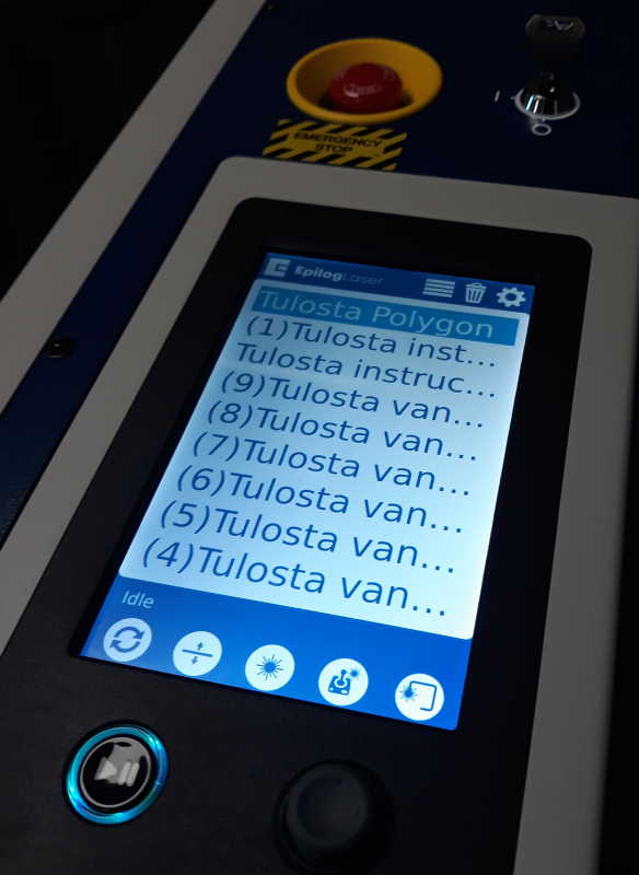
This one has a list of items that are sent to cutter. One on top is the newest one. This menu can be opened by pressing 4 lines at top of screen. After selecting right file from list I pressed play-button to begin the cut.
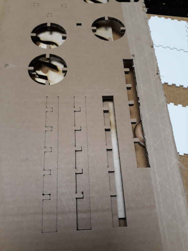
Cardboard was intresting material to work with because it seemed to have different thicknesses. For example with these pillars few lines were not cut.
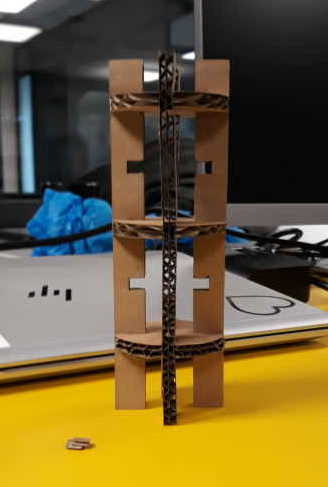
And here was the final product before making more pieces. It worked like I had imagined although cardboard bended pretty easily. Filler pieces totally failed because of the layers inside cardboard. Few of those had the form but even then it was impossible to get them inside of empty slots.
After speaking with local instructor I decided to to create another piece for kit. This was created much quicker because of previous challenges and overall use of Fusion started to make a difference.
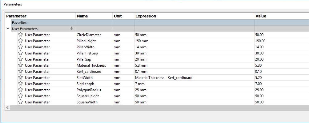
Close up to final parameters presented earlier.
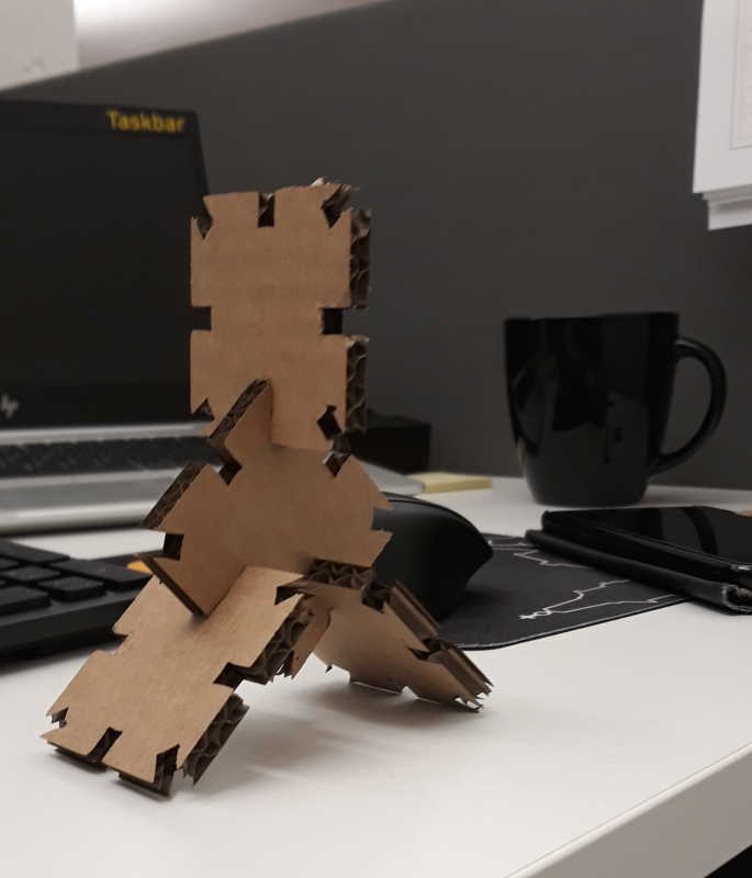
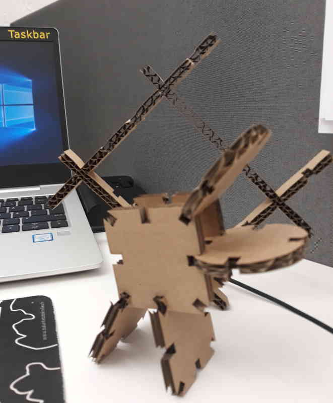
Here are the final products. I tried come up with something using more of the pieces. as after thought it would have been better to use chamfer joints instead of press-fit. With press-fit corners of the slots were damaged.
Problem with Fusion
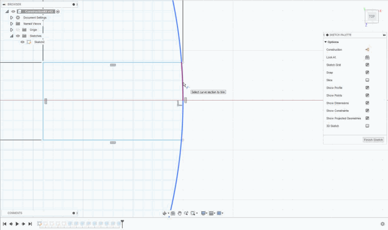
I had few problems when trying to change size of circle. It took a while testing solutions, but in the end problem seemed to be those so small lines which went over the edge of main object. After heavy use of zoom finally found and trimmed all the extra lines.
After changing parameters this is what initially happened to my sketch. Some parts didn't scale right especially around slots.
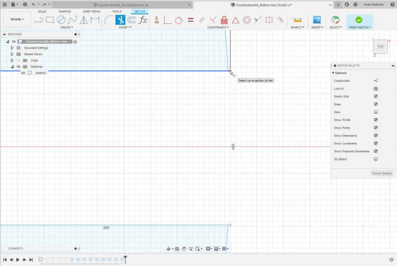
It took a while to realize where the problem was. We were discussing about this with local instructor Behnaz and she advised to take a closer look of the outlines. After using a lot zoom I finally found these anchors from slots which were outside of the circle and these were the problem.
After adjusting the anchors from the slots to be at outline of circle instead of outside I could corretly adjust size of the circle by changing parameters.
Group assignment
I worked in same group on this week with Achille, Hannu, and Jari. Our group assignment can be found from Jari's site.
Learnt from group assignment:
- How to test kerf of a laser
- How settings change the result on a laser cutter. By changing one variable, e.g. Speed, can have a huge difference to end result. With high speed laser is more likely to just scratch the face, but with very slow speed it burns the material. Speed and power seemed to have biggest effect to the result.
Kerf has a big impact on a cut and should be taken on account on the design. Kerf value is different for every a machine and it changes if parts are replaced. Also settings such as speed have a impact on the amount of kerf. It is also important to think for a while when design does the kerf have to be decreased or added to material thickness. As a main rule kerf should be added if the cut is outside of the object and taken off when cutting from inside of the object.
Focus is another important aspect when cutting with laser. Focus can be set manually or automatically. Focus is a certain distance between the laser and face of the object which is optimal for use.
Reflection
It was fun to start using machines finally instead of just using computer. Kinda regret that I did not create construction kit from other materials after using cardboard although we used mdf and acrylic in group assignment. It was interesting to see how different settings changed the way laser cut materials.
I could have also used better variables in my parametric design. Used them on very basic level. In the future these will be useful.
Vinyl cutter quite interesting machine to use, but don't have currently many ideas what to do with it in the future. I was amazed how easy and fast it was to create a sticker with it. Afterwards I've learned that it can be used for creating PCB which sounds interesting.
Files
Taskbar (pdf)Taskbar (svg)
Circle (pdf)
Filler (pdf)
Pillar (pdf)
Polygon (pdf)
Constructionkit (stl)
ConstructionKit (f3d)